Siamp VERSO BCM 800 Quick guide

GB
VERSO
ASSEMBLY AND MAINTENANCE MANUAL

2
a
c
d
e
h
i
j k
m
n
o
p
q
r
l
f
g
b

3
2
• Set of wrenches from 8 to 19 mm
• Hack saw
• Electric drill + bit dia 10 mm
• Spirit level
• Pencil + ruler
• Tape measure
• Hammer
• Screw driver
•‑ Keep the product package during
installation: there is a cutting template
on the back
•‑ Keep these instructions safety for any
maintenance operations.
Float valve
Shut‑off valve
Mechanism
PSE template
Supply bend
Supply bend cap
Toilet pipe cap
Supply sleeve
Bowl attaching kit
Flexible sheaths (x 2)
Pipe attaching collar
Toilet bowl attaching rods (x 2)
Setscrew (x 2)
Adjustable foot (x 2)
Screw plug (x 8)
Plug (x 8)
Toilet bowl stud attaching tab (x 2)
Attaching bracket
a
b
c
d
e
f
g
h
i
j
k
l
m
n
o
p
q
r
White double volume plate Ref. 31 1802‑10
Chrome double volume plate Ref. 31 1852‑10
Bent drain kit Ref. 92 4000‑07
Straight drain kit Ref. 92 4010‑07
Bent pipe
Frame
Straight pipe
Drain
sleeve
Manchon
d’évacuation
Screws (x 4)
Plate

4
➊ Wall fixing
I ‑ Frame depth = 180 to 245 mm
II ‑ Thickness of front cladding =
between 20 and 100 mm
III ‑ Thickness of top cladding =
between 25 and 60 mm
IV ‑ Height = Adjustable from 800
to 1000 mm
V ‑ Height of toilet bow
= 400 mm (finished floor level)
VI ‑ Maximum thickness of finished flooring
= 185 mm
I II
IV III
VI V
✓OK 0K
230mm
400mm

4
5
➊ Measure the center distance of the toilet
bowl (A)
➋ Insert the rods (I) into the holes of the frame,
corresponding to the center distance
➌ Position the frame in place
➍ Secure the attaching tabs (q) to the rods (l),
position the assembly against the wall and
lock with the nuts.
➎ Position the wall mounting bracket (r) against
the wall and attach it with the nuts, first
checking that the frame is vertically level
➏ Use a hacksaw to cut the threaded rods of the
bracket protruding from the frame
➊ Position the frame in its final location
➋ Undo the 2 setscrews (m)
➌ Adjust the height of the feet so that the top of the toilet
bowl is at a height of 400 mm from the finished floor level.
➍ Check that the frame is level (vertically and horizontally) and
tighten the setscrews
If the frame is being attached to an unfinished floor surface,
the maximum thickness of the finished floor surface shall
not be more than 185 mm.
A
➊
A = 180 mm
A = 230 mm
➍
➎
➏
m

6
➊ Mark the drilling points (6 for wall and 2 for floor)
➋ Remove the frame and drill to a depth of 70 mm at the least, using
an 10 mm diameter drill bit
➌ Position the screw plugs in the holes
➍ Move the frame back in place and connect the drain pipe
➊ Attach the collar (k)
➋ Position the drain outlet pipe
➌ Tighten the collar (k)
Before gluing the drain outlet pipe to the main drain
pipe, ensure that the frame is correctly positioned.
If the drainpipe is not opposite the outlet pipe, the
connection can be made using PVC bends and
couplings.
Bend outlet
Straight outlet
➋➌
x 6
x 2
➊
k

7
6
➊ Mark the drilling points (6 for wall and 2 for floor)
➋ Remove the frame and drill to a depth of 70 mm at the least, using
an 10 mm diameter drill bit
➌ Position the screw plugs in the holes
➍ Move the frame back in place and connect the drain pipe
➊ Attach the frame definitively
x 2
➊ Insert the water supply tube in the cistern
➋ Connect your pipe to the shut‑off valve
(b) either using the dual cone supplied or
directly with the nuts provided on the water
inlet (in this case, ensure tightness using
a fibre washer)
➌ Connect the shut‑off valve (b) to the float
valve (a) (ensure tightness by a fibre
washer).
b
a

8
➊
➍
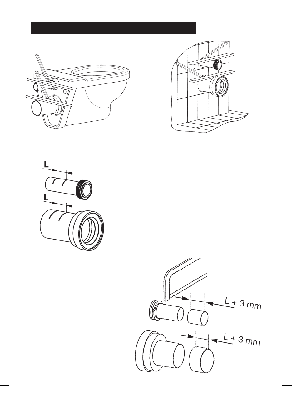
➊ Insert the supply sleeve (h) and the drain
sleeve on the toilet bowl
➋ Position the toilet bowl on the frame
➌ Turn on the water using the shut‑off valve (b)
and wait until the toilet bowl fills
➍ Manually operate the mechanism (c) using
the flush‑pull control
➎ Check the tightness of the supply and drain
connections
➏ Close the shut‑off valve and drain the
cistern
➐ Remove the toilet bowl
c
Silicone
Grease
➋
➐

9
8
➊ Fasten the PSE template (d) on the access trap
using two grey screws which can be found in the
control panel box
➋ Fit the caps (f) and (g) on the supply bend (e) and
on the drain pipe as well as the flexible sheaths
(i) over the attaching rods of the toilet bowl (l)
The thickness of the cladding must be between 20 and 100 mm (for
the front) and 25 and 60 mm (for the top) and must be firmly attached
to the building structure.
Cladding can be of various materials (brick, plaster blocks, plaster board,
water repellent wood panels etc).
Cut the various holes (control panels and drain and supply of toilet bowl
and toilet bowl attaching holes). There is a cutting template included on
the back of the package.
d
f
g
10
➊ Using a rule placed as shown in the above drawing,
draw a mark on the toilet bowl side, on the two
sleeves.
➋ Remove the sleeves from the toilet bowl and fit them
to the frame. Using a rule placed as shown in the
drawing above, make a mark on the wall side, on
the two sleeves
➌ For each of the sleeves, measure the dimension
(L) between the two marks.
➍ Transfer this dimension (L) by
increasing by 3 mm at the end
(frame side) the size obtained on
each sleeve. For instance, if L = 50
mm, shorten the sleeve by 53 mm.
➎ Cut the sleeves using a hack saw.

11
10
➋ Remove the sleeves from the toilet bowl and fit them
to the frame. Using a rule placed as shown in the
drawing above, make a mark on the wall side, on
the two sleeves
➏ Deburr the cut pipes using a file
➐ Measure the thickness at the rear of the toilet
bowl (B)
➑ If necessary, cut the attaching rods (I) so that
the part protruding from the wall measures (B)
+ 20 mm
➒ Shorten the flexible sheaths (j) so that the part
protruding from the wall measures (B) ‑ 15 mm
l
j
B + 20 mm
➓ Fit the supply sleeve (h) and the drain
sleeve onto the toilet bowl.
Then position the toilet bowl on the
two attaching rods.
To facilitate the fitting of the drain
sleeve onto the bowl and the pipe,
use soapy water.
B
Silicone
Grease
12
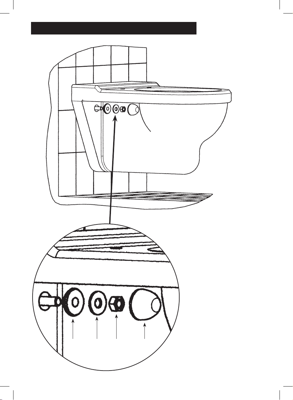
➊ When the toilet bowl is correctly
positioned, attach it using the kit (i)
complying with the part stacking order:
i = centering washer
ii = metal washer
iii = nut
iv = cover
ii iii iv
13
12
➊ When the toilet bowl is correctly
positioned, attach it using the kit (i)
complying with the part stacking order:
i = centering washer
ii = metal washer
iii = nut
iv = cover
15 mm
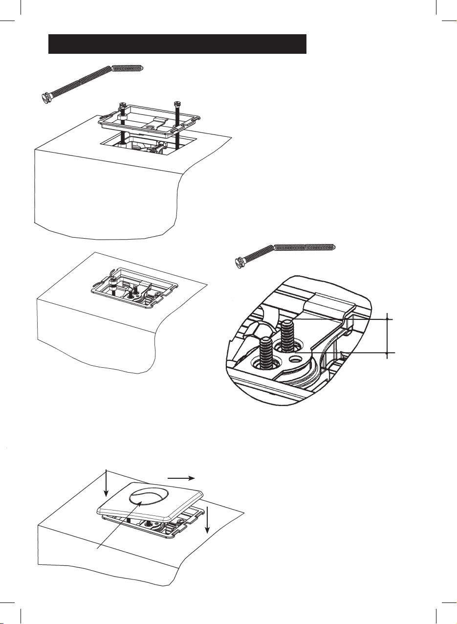
➊ Fasten the frame with two grey screws
If the cladding is not very thick, shorten the
screws by simply breaking them at the notch
intended for this purpose.
➍ Put the control panel in place.
A ‑ Position the panel (small button at the front) on
the frame spring (left side)
B ‑ Pull over to the right
C ‑ Place panel on cladding and release
➋ Break off the heads of the remaining screws
at the highest point (throw away the head part)
➌ Screw the two remaining parts into the
mechanism so that the tops are 15 mm
higher than the stirrup
A
B
C
Small button

14
During the use of your VERSO BCM 800 flushing cistern, you may be required to maintain
the equipment.
I - MAINTENANCE OF THE VALVE (filter cleaning, replacement of membrane)
➊ Remove the panel
A ‑ Push towards the right
B ‑ Lift up panel on the right‑hand side
C ‑ Remove panel
➋ Unscrew and remove frame
➌ Unscrew one of the plate screws
➍ Remove the plate and the spacer
➎ Close the shutoff valve (b) and separate it from the
float valve (a).
➏ Turn the spacer supporting the valve and remove the
valve
➐ After operation repeatedly operations in the opposite
order, taking care to reopen the shut‑off valve (b) and
re‑locate the spacer
Spare parts:
Membrane: P/N 349513‑07
Complete valve: P/N 309503‑07
➊
➋
➌
b
a
➍
Membrane
C
A
B

15
14
During the use of your VERSO BCM 800 flushing cistern, you may be required to maintain
the equipment.
I - MAINTENANCE OF THE VALVE (filter cleaning, replacement of membrane)
II - MECHANISM MAINTENANCE (cleaning or replacement of the seal)
Proceed in the same way as for the maintenance of the valve up to point
➍ then:
➊ Grasp the mechanism by the base and remove it from the cistern
Spare parts:
Seal P/N 34 2332‑07
Complete mechanism: P/N 32‑4544‑07
➋ When maintenance is over, repeat all the steps in the opposite order.
To position the mechanism properly it is provided with a polariser on the base
Seal

You have just installed a cistern frame forming part of the VERSO range by
SIAMP and we would like to thank you for your confidence in our products.
As expert in technical equipment and accessories for the toilet, SIAMP has
taken every possible measure to apply all the necessary care to the design and
production of this product, offering a ten‑year guarantee except for rubber parts
and manpower.
For any complementary information, or indicated claim, please contact your dealer.
Or contact directly:
4, quai Antoine 1er - BP 219 - MC 98007 MONACO Cedex
Site Internet : http://www.siamp.com
Réf. 5627
Table of contents
Other Siamp Toilet manuals


Popular Toilet manuals by other brands

Kohler
Kohler Sterling Windham 402315 installation instructions

American Standard
American Standard Ultima VorMax 203AA.104 owner's manual

Sun-Mar
Sun-Mar CENTREX 1000 owner's manual

Uspa
Uspa UB-7035R Operating instructions manual

Kohler
Kohler HARKEN K-22695T-S installation instructions

Cinderella
Cinderella Comfort NA owner's manual


Swiss Madison
Swiss Madison SM-2T130 installation instructions

THE BOLD LOOK OF KOHLER
THE BOLD LOOK OF KOHLER K-4647 installation guide

Dometic
Dometic SeaLand MasterFlush MF 7200 Series Operation manual

Kohler
Kohler SAN SOUCI K-21865T-ITHC2 installation instructions

clivus multrum
clivus multrum CM8 installation manual

Porcelanosa
Porcelanosa Noken URBAN C 100160146 N369225479 manual