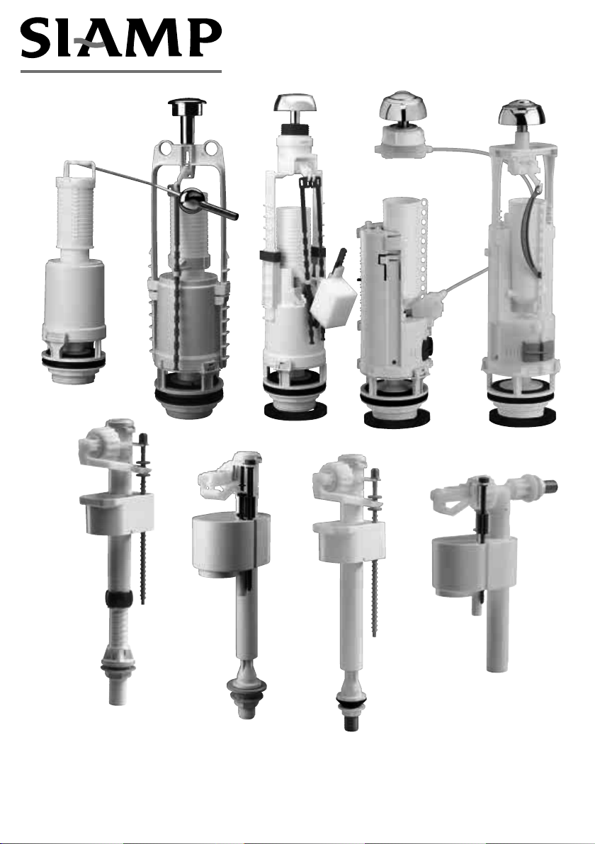
Siamp 50 6189 00 User manual
ASSEMBLY
INSTRUCTIONS
N 50N 100
Asean

Adjusting screw
Backnut
COMPACT 99B / 93B
➊Place inlet valve through inlet hole with inlet
rubber washer inside the cistern
➋Secure with backnut
➌Connect the supply
➍Adjust water level
with grey adjusting screw.
N.B. Ensure tightness of connection to cistern with filter
gasket.
WARNINGS:
1 - Do not overtight in any case.
2 - Do not use any sealing paste and/or compound in any case
3 - Do not use connector handling the internal part of the
inlet valve.
SIAMP will be not responsible in case these warnings are
not respected.
Seal
Inlet
rubber
washer
COMPACT 99T WITH TELESCOPIC TUBE
➊Adjust telescopic tube
(a) raise the grey blocking ring
(b) screw or unscrew the gradiated tube
in way so that the inlet top not exceed
the top of the tank
(c) position back the grey ring
➋Place inlet valve through inlet hole with inlet
rubber washer inside the cistern
➌Secure with backnut
➍Connect the supply
➎Adjust water level
with grey adjusting screw.
N.B. Ensure tightness of connection to cistern with filter
gasket.
WARNINGS:
1 - Do not overtight in
any case.
2 - Do not use any
sealing paste and/
or compound in any
case
3 - Do not use connector
handling the internal
part of the inlet valve.
SIAMP will be not responsible in case these warnings are
not respected.
Adjusting screw
Backnut
Filter seal
Inlet
rubber
washer
MAINTENANCE
Membrane
Blocking ring
(b)
(a)
(c)
2

HANDY 93T WITH TELESCOPIC TUBE
➊Adjust telescopic tube
(a) raise the grey blocking ring
(b) screw or unscrew the gradiated tube
in way so that the inlet top not exceed
the top of the tank
(c) position back the grey ring
➋Place inlet valve through inlet hole with
inlet rubber washer inside the cistern
➌Secure with backnut
➍Connect the supply
➎Adjust water level
with grey adjusting screw.
N.B. : Make connecting tightness
with fibre seal other than any
corrosive joint compound
Adjusting screw
Backnut
Fibre seal
Inlet
rubber
washer
Blocking ring
(b)
(a)
(c)
HANDY 93L
➊Place inlet valve through inlet
hole
➋Secure with backnut
➌Connect the supply
➍Adjust water level
with grey adjusting screw.
N.B. : Make connecting tightness
with fibre seal other than any
corrosive joint compound
Adjusting screw
Backnut
Fibre seal
3
H
D
➍
➊
➌
➎
➏➐
➋
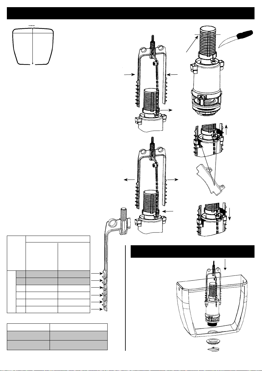
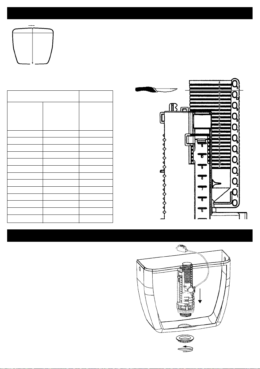
I - PREPARATION OF THE MECHANISM 33A/22A
Measure the cistern:
- H (from top of lid to inside bottom of cistern)
- D (diameter of hole in lid)
Check the positioning of the stirrup
if the stirrup is positioned correctly with
reference to the table below, move on
to step ➑; otherwise, go through all the
following steps in order:
➊Unclip the pulls
➋Remove the pins
➌If necessary, cut the overflow as shown in
the table
➍Squeeze the stirrup and then move it to
defined podition (P)
➎Relax the stirrup and ensure the clipping
into the strap
➏Clip on the lift rod
➐Block the stirrup with the 2 grey blocking
clips
➑Unscrew the nut
Height of cistern H
Diameter D Diameter D
of hole of hole
in lid from in lid from
16 to 36 mm &
37 to 42 mm
43 to 50 mm
1* 307 to 325 325 to 343
2* 326 to 340 344 to 358
3 341 to 355 359 to 373
4 356 to 370 374 to 388
5 371 to 385 389 to 403
6 386 to 400 404 to 418
Position (P)
Stirrup notch Overflow
1 Cut between E and F
2 Cut between B and C
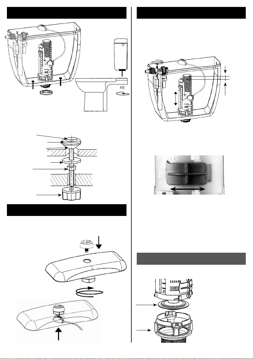
II - INSTALLATION
Position the mechanism in the
cistern and attach
it with the nut.
4
5
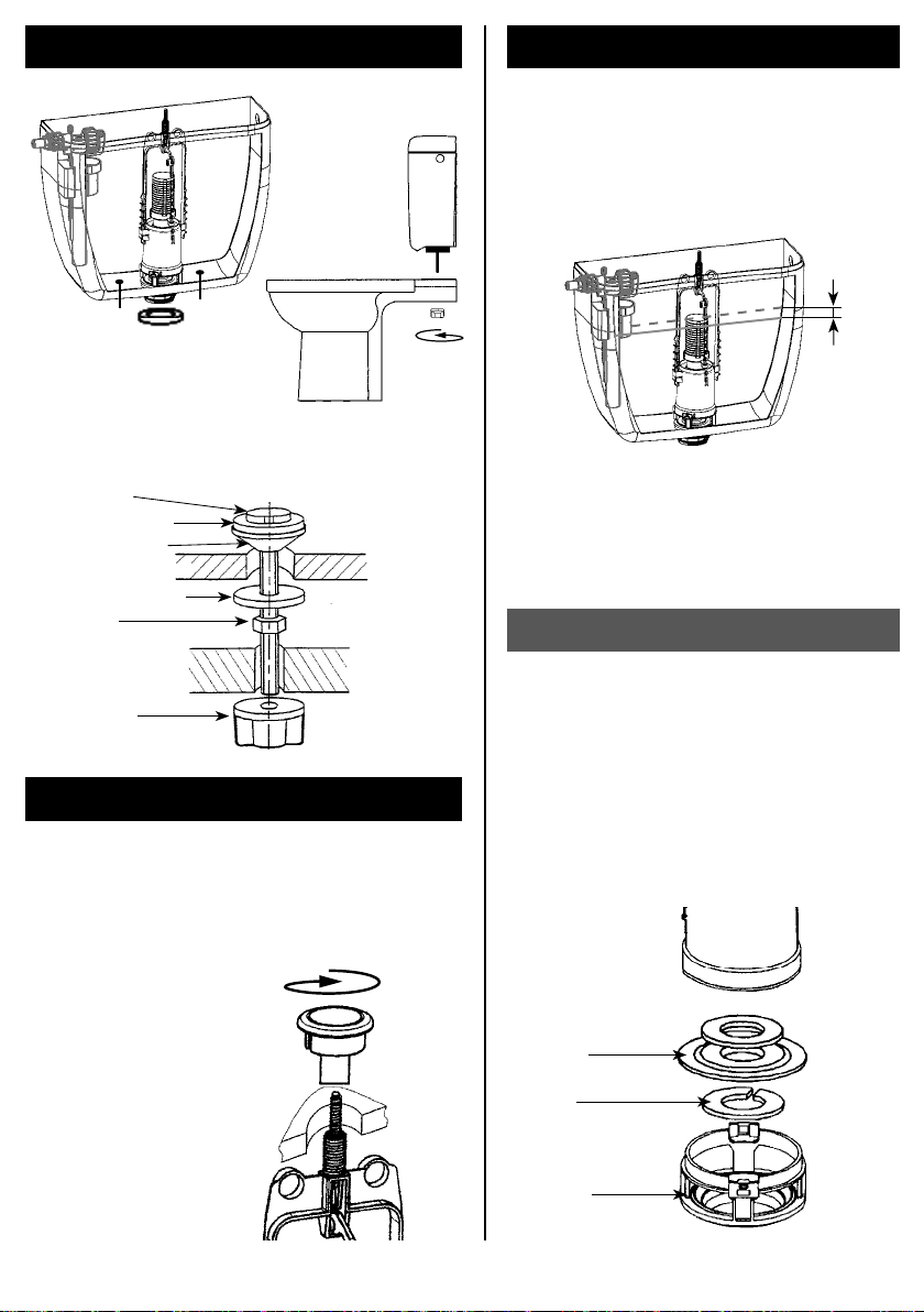
III - ASSEMBLY OF CISTERN TANK
➊Attach the screws to the
bottom of the cistern (see
stack of parts indicated
below
➋Position the foam seal on
the nut
➌Position the cistern
on the toilet bowl and
attach it with the wing
nuts
IV - ADJUSTMENT OF WATER LEVEL
First connect your float valve to the water system,
open the stop valve and adjust the water level using
the float valve (see page 2 or 3).
Note: The max. water level should be 20 mm lower
than the overflow tube.
Overflow
Maximum
water level
20 mm
V - INSTALLING THE BUTTON
➊Once you have finished adjusting, fit the lid.
➋If the lid hole (D) is < 37 mm and > 42,
remove the rose
➌Position the button on the lid and screw down
(without pushing the central part) until it locks
NB : For the model
SWITCH 22A push once
to flush. Pussh again to
interrupt.
VI - MAINTENANCE
Replacement of the seal
➊Open the cistern and turn the mechanism a
quarter turn to separate it from the plug
➋Remove the seal attaching clip
➌Replace the seal
➍Fit the clip then relocate the mechanism,
locking it on the plug
➎Close the cistern making sure that the control
button is correctly assembled (see § V)
Seal
Clip
Plug
Bottom of tank
Cistern wall
Screw M6x78
Tapered joint
Hexagonal nut
Washer
Wing nut
Washer

6
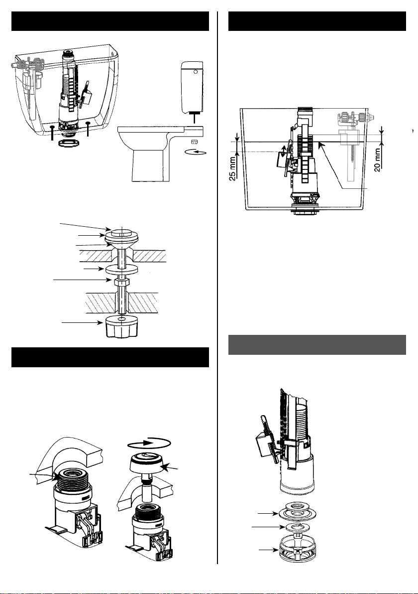
I - PREPARATION OF THE MECHANISM 36A
II - INSTALLATION
Check the positioning of the stirrup
if the stirrup is positioned correctly with
reference to the table below (pin clipped
into the right notch), move on to step ➒;
otherwise, go through all the following
steps in order:
➊Unclip the pulls
➋Remove the pins
➌Remove the stirrup
➍If necessary, cut the overflow as shown in
the table
➎If necessary, cut the pulls
➏Set the stirrup in the suitable notch - see
table
➐Attach the stirrup again using the pins
➑Clip the pulls back in place
➒Clip the small float in place
➓Unscrew the nut
Measure the cistern:
- H (from top of lid to inside
bottom of cistern)
- D (diameter of hole in lid)
Height of cistern H
Diameter D Diameter D
of hole of hole
in lid from in lid from
18 to 38 mm &
38 to 44 mm
45 to 50 mm
10* 293 to 310 312 to 329
9* 309 to 325 328 to 344
8* 324 to 341 343 to 360
7 340 to 356 359 to 375
6 355 to 371 374 to 391
5 370 to 387 390 to 406
4 386 to 402 405 to 422
3 401 to 417 421 to 437
2 416 to 432 436 to 453
1 431 to 447 452 to 468
Stirrup adjusting notch
H
D
➋
➐
➌
➏
➊
➑
➒
➍
Stirrup notch Overflow Pulls
10 Cut between I and J Cut
9 Cut between F and G at 50 mm
8 Cut between C and D from base
Position the mechanism in the cistern and attach
it with the nut.
NB: The small float should
be on the opposite side
to the water inlet.
➓
Position the mechanism in the cistern and attach
it with the nut.
NB: The small float should
be on the opposite side
to the water inlet.
7
Bottom of tank
Cistern wall
Screw M6x78
Tapered joint
Hexagonal nut
Washer
Wing nut
Washer
IV - ADJUSTMENT OF HALF FLUSH
III - ASSEMBLY OF CISTERN TANK
V - INSTALLING THE BUTTON
VI - MAINTENANCE
➊Attach the screws to the
bottom of the cistern (see
stack of parts indicated
below
➋Position the foam seal on
the nut ➌Position the cistern
on the toilet bowl and
attach it with the wing
nuts
Replacement of the seal
➊Open the cistern and
turn the mechanism
a quarter turn to
separate it from the
plug
➋Remove the seal
attaching clip
➌Replace the seal
➍Fit the clip then
relocate the
mechanism, locking it
on the plug
➎Close the cistern
making sure that
the control button is
correctly assembled
(see § V)
Seal
Clip
Plug
First connect your float valve to the water system, open
the stop valve and adjust the Full flush level using the
float valve (see page 2 or 3).
NB: the maximum water level should be 20 mm below
the overflow.
➊Fill the cistern to the maximum level (as
indicated above)
➋Slide the small float along the gray rocker so that
it is 25 mm at least below the water level.
NB: The more you depress the small float, the more
flushing water you will have (minimum possible
3 liters).
➊Once you have finished adjusting, make sure that
the gray collar (C) is unscrewed entirely.
➋Fit the lid
➌If the lid hole (D) is < 38 mm and > 44, remove the
rose (B)
➍Position the button on the lid and screw down until
it locks.
B
C
Overflow
Maximum
water level

8
I - PREPARING THE MECHANISM 49
II - INSTALLATION
Check the position of the stirrup
If the stirrup is correctly positioned on
the basis of the below table, proceed to
step ➏. Otherwise, carry out all of the
following steps:
➊Unclip the lift rod
➋Remove the stirrup (m) , by pressing on
the two catch clips
➌Cut the overflow if necessary according to
the table
➍Reposition the stirrup in its seat and slide
it to the required position (desired setting
notch number visible)
➎Clip lift rod back into the hole of the
overflow which has the same number as
that of the setting notch
➏Unscrew the strainer nut
Measure the cistern
-H (from the top of the lid to the inside base of the cistern)
-D (diameter of the hole in the lid)
Height Hof cistern
Diameter D Diameter D
of hole in lid of hole
18 to 38 mm in lid
and 38 to
45 to 50 mm 44 mm
11 430 to 417 448 to 435
10 416 to 405 434 to 423
9 404 to 393 422 to 411
8 392 to 381 410 to 399
7 380 to 369 398 to 387
6 368 to 357 386 to 375
5 356 to 345 374 to 363
4 344 to 333 362 to 351
3 332 to 321 350 to 339
2 320 to 309 338 to 327
1 308 to 297 326 to 315
Mini
296 to 282 314 to 300
No. of notch visible on lift rod
H
D
➌
➍
Stirrup notch Cut on overflow tube
3 C mark visible
2 F mark visible
1 I mark visible
Mini L mark visible
Position the mechanism
in the cistern and secure
it in place with the nut
➊
➋
➊+ ➋=
Visible stirrup notch
no. 4 = position of lift rod no. 4
➎

9
IV - SETTING WATER LEVEL
III -
ASSEMBLING BOWL AND CISTERN
V - INSTALLATION OF BUTTON
VI - MAINTENANCE
Bottom of cistern
Wall of bowl
Conical seal
Hexagon nut
Washer
Wing nut
Washer
➊Fix screws at the bottom
of the cistern (see order of
parts below)
➋Position the latex foam
gasket on the nut
➌Position the cistern on
the bowl and secure it
with wing nuts
Changing the valve gasket
➊After having opened
the cistern, turn the
mechanism 90° to
separate it from its
strainer
➋Change the valve
gasket
➌Reposition the
mechanism, locking
it into the strainer
➍Close the cistern
again.
Valve gasket
Strainer
After having connected your ballcock to the water
supply, open the tap and set the level of the long flush
using the ballcock (see overleaf).
Note: The max. water level should be 20 mm lower
than the overflow tube.
To adjust the water level of the short flush, slide the
cursor along.
Note : The closer the cursor is to 18, the more
water will be flushed.
➊Once the set-up has been completed, put on the lid
on the cistern
➋If the hole in the lid (D) is > 38 mm and < 45 mm,
remove the escutcheon
➌Position the button on the lid and screw until tight.
20 mm
Overflow
Max.
water level
In some (rare) cases, the residual water level
(amount of water remaining after the long flush)
must be increased to ensure more efficient
cleaning. To do this, move the sliding valve to the
left (the more it is open, the more the residual water
increases).
Note: Increasing the residual water reduces the
volume of water flushed. If necessary, readjust the
max. water level using the ballcock.
M6x78 screw
10
I - PREPARING THE MECHANISM 50
II - INSTALLATION
➊In the table below, choose the right level
for the overflow shortening
➋Unscrew the strainer nut
Measure the cistern
-H (from the top of the lid to the inside base of the cistern)
-D (diameter of the hole in the lid)
H
D
Position the mechanism in the cistern
and secure it in place with the nut
Height H Overflow tube
of cistern shortening
Diameter D Diameter D
of hole in lid of hole
18 to 38 mm in lid Cut between
and 38 to
45 to 50 mm 44 mm
> 332 mm > 350 mm No cut
327 to 332 345 to 350 A and B
322 to 326 340 to 344 B and C
317 to 321 335 to 339 C and D
312 to 316 330 to 334 D and E
307 to 311 325 to 329 E and F
302 to 306 320 to 324 F and G
297 to 301 315 to 319 G and H
292 to 296 310 to 314 H and I
287 to 291 305 to 309 I and J
282 to 286 300 to 304 J and K
277 to 281 295 to 299 K and L
272 to 276 290 to 294 L and M
11
IV - SETTING WATER LEVELIII -
ASSEMBLING BOWL AND CISTERN
V - INSTALLATION OF BUTTON
VI - MAINTENANCE
Bottom of cistern
Wall of bowl
Conical seal
Hexagon nut
Washer
Wing nut
Washer
➊Fix screws at the bottom
of the cistern (see order of
parts below)
➋Position the latex foam
gasket on the nut ➌Position the cistern on
the bowl and secure it
with wing nuts
Changing the valve gasket
➊After having opened
the cistern, turn the
mechanism 90° to
separate it from its
strainer
➋Change the valve
gasket
➌Reposition the
mechanism, locking
it into the strainer
➍Close the cistern
again.
Valve gasket
Strainer
After having connected your ballcock to the water
supply, open the tap and set the level of the long flush
using the ballcock (see overleaf).
Note: The max. water level should be 20 mm lower
than the overflow tube.
To adjust the water level of the short flush, slide the
cursor along.
Note : The closer the cursor is to 18, the more
water will be flushed.
➊Once the set-up has been completed, place button
on lid and screw button nut, (if the hole in the lid (D)
is > 38 mm and < 45 mm, remove the escutcheon)
➋Clip cable case
➌Place lid back on top of cistern
In some (rare) cases, the dead water level (amount
of water remaining after the long flush) must be
increased to ensure more efficient cleaning. To do
this, move the sliding valve to the left (the more it is
open, the more the residual water increases).
Note: Increasing the dead water reduces the
volume of water flushed. If necessary, readjust the
max. water level using the ballcock.
M6x78 screw
20 mm
Overflow
Max.
water level
(k)

Ref. 50 6189 00 A
12
➊Position the mechanism in the cistern and attach it with the nut.
I - INSTALLATION 41
II - ASSEMBLY OF CISTERN TANK
➊Attach the screws to the bottom of the cistern
(see stack of parts indicated below
➋Position the foam seal on the nut
➌Position the cistern on the
toilet bowl and attach it
with the wing nuts
Bottom of tank
Cistern wall
Screw M6x78
Tapered joint
Hexagonal nut
Washer
Wing nut
Washer
III - INSTALLATION OF CONTROL SYSTEM
➊➋
➌
Table of contents
Other Siamp Toilet manuals


Popular Toilet manuals by other brands


JABSCO
JABSCO 37010 Series quick start guide

Dometic
Dometic SeaLand MasterFlush 8900 Series installation instructions

DURAVIT
DURAVIT SENSOWASH 610001 operating instructions

SFA-SANIFLO
SFA-SANIFLO SANIGRIND Installation and maintenance instructions

Geberit
Geberit AQUACLEAN CAMA user manual

ForU
ForU AVA04 Installation and instruction manual