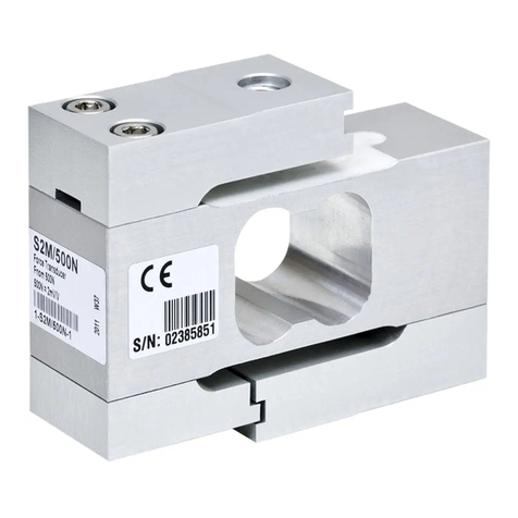
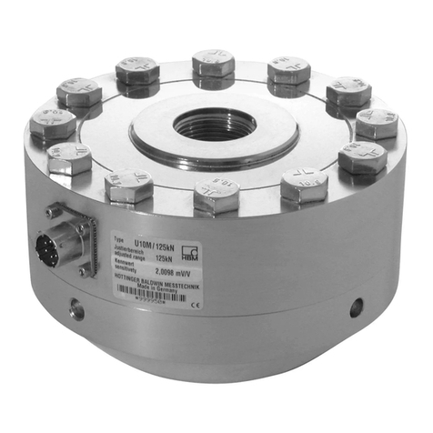
HBM S9M User manual

A3019-5.0 en/de/fr
Force transducer
Kraftaufnehmer
Capteur de force
S9M
Mounting Instructions
Montageanleitung
Notice de montage

English Page 3 - 23. . . . . . . . . . . . . . . . . . . . . . . . . . . . . . . . . . . . . . . . . . . . . . . . .
Deutsch Seite 25 - 45. . . . . . . . . . . . . . . . . . . . . . . . . . . . . . . . . . . . . . . . . . . . . . .
Français Page 47 - 68. . . . . . . . . . . . . . . . . . . . . . . . . . . . . . . . . . . . . . . . . . . . . . .

3
S9M
A3019-5.0 en/de/fr HBM
Contents Page
English
Safety instructions 4. . . . . . . . . . . . . . . . . . . . . . . . . . . . . . . . . . . . . . . . . . . . . .
1 Scope of delivery 8. . . . . . . . . . . . . . . . . . . . . . . . . . . . . . . . . . . . . . . . . . . .
2 Application instructions 8. . . . . . . . . . . . . . . . . . . . . . . . . . . . . . . . . . . . . .
3 Structure and mode of operation 9. . . . . . . . . . . . . . . . . . . . . . . . . . . . . .
3.1 Measuring body 9. . . . . . . . . . . . . . . . . . . . . . . . . . . . . . . . . . . . . . . . .
3.2 Strain gage covering 9. . . . . . . . . . . . . . . . . . . . . . . . . . . . . . . . . . . . .
4 Conditions on site 10. . . . . . . . . . . . . . . . . . . . . . . . . . . . . . . . . . . . . . . . . . .
4.1 Ambient temperature 10. . . . . . . . . . . . . . . . . . . . . . . . . . . . . . . . . . . . .
4.2 Moisture and humidity 10. . . . . . . . . . . . . . . . . . . . . . . . . . . . . . . . . . . .
4.3 Deposits 10. . . . . . . . . . . . . . . . . . . . . . . . . . . . . . . . . . . . . . . . . . . . . . . .
5 Mechanical installation 12. . . . . . . . . . . . . . . . . . . . . . . . . . . . . . . . . . . . . . .
5.1 Important precautions during installation 12. . . . . . . . . . . . . . . . . . . .
5.2 General installation guidelines 12. . . . . . . . . . . . . . . . . . . . . . . . . . . . .
5.3 Mounting the S9M 13. . . . . . . . . . . . . . . . . . . . . . . . . . . . . . . . . . . . . . .
5.3.1 Mounting with tension/compression bars 13. . . . . . . . . . . . . .
5.3.2 Mounting with direct connection 14. . . . . . . . . . . . . . . . . . . . . .
5.3.3 Mounting with knuckle eyes 14. . . . . . . . . . . . . . . . . . . . . . . . .
6 Electrical connection 18. . . . . . . . . . . . . . . . . . . . . . . . . . . . . . . . . . . . . . . . .
6.1 Connection with six-wire circuitry 18. . . . . . . . . . . . . . . . . . . . . . . . . .
6.2 Shortening the cable 18. . . . . . . . . . . . . . . . . . . . . . . . . . . . . . . . . . . . .
6.3 Cable extension 19. . . . . . . . . . . . . . . . . . . . . . . . . . . . . . . . . . . . . . . . .
6.4 EMC protection 19. . . . . . . . . . . . . . . . . . . . . . . . . . . . . . . . . . . . . . . . . .
7 Specifications (VDI/VDE2638 standards) 20. . . . . . . . . . . . . . . . . . . . . . .
8 Dimensions 22. . . . . . . . . . . . . . . . . . . . . . . . . . . . . . . . . . . . . . . . . . . . . . . . .
8.1 S9M with nominal force range 0.5kN to 2kN 22. . . . . . . . . . . . . . . .
8.2 S9M with nominal force range 5kN to 50kN 22. . . . . . . . . . . . . . . . .
8.3 Mounting aids 23. . . . . . . . . . . . . . . . . . . . . . . . . . . . . . . . . . . . . . . . . . .

S9M
4
A3019-5.0 en/de/frHBM
Safety instructions
Designated use
The force transducers in the type series S9M are solely designed for measur
ing static and dynamic tensile and/or compressive forces within the load limits
specified by the technical data for the respective maximum capacities. Any
other use is not the designated use.
To ensure safe operation, the regulations in the assembly and operating in
structions, together with the following safety rules and regulations, and the
data specified in the technical data sheets, must be complied with. It is also
essential to observe the applicable legal and safety regulations for the ap
plication concerned.
The force transducers are not intended for use as safety components. Please
also refer to the section: ”Additional safety precautions”. Proper and safe op
eration of the force transducer requires proper transportation, correct storage,
siting and mounting, and careful operation.
Operating personnel
Mounting and operation of the force transducer may only be carried out by
fully qualified personnel. Qualified personnel in this respect means persons
entrusted with siting, mounting, starting up and operating the product, who are
familiar with the operation of the force transducer and possess the appropriate
qualifications for their function.
Loading capacity limits
The data in the technical data sheet must be complied with when using the
force transducer. In particular, the respective maximum loads specified must
never be exceeded. The following limits set out in the technical data sheets
must not be exceeded
•Load limits
•Lateral load limits
•Breaking loads
•Permissible dynamic loads
•Temperature limits
When several force transducers are connected, it must be noted that the load/
force distribution is not always uniform.
Use as a machine element
The force transducers can be used as machine elements. When used in this
manner, it must be noted that, to favor greater sensitivity, the force transducer

5
S9M
A3019-5.0 en/de/fr HBM
cannot be designed with the safety factors usual in mechanical engineering.
Please refer here to the section ”Loading capacity limits” and the technical
data.
Additional safety precautions
The force transducers cannot (as passive transducers) implement any (safe
ty-relevant) cutoffs. This requires additional components and constructive
measures for which the installer and operator of the plant is responsible.
In cases where a breakage or malfunction of the force transducer would
cause injury to persons or damage to equipment, the user must take appropri
ate additional safety measures that meet at least the requirements of applica
ble safety and accident prevention regulations (e.g. automatic emergency
shutdown, overload protection, catch straps or chains, or other fall protection).
The layout of the electronics conditioning the measurement signal should be
such that measurement signal failure does not cause damage.
General dangers of failing to follow the safety instructions
The force transducers are state-of-the-art and reliable. Transducers can give
rise to remaining dangers if they are incorrectly operated or inappropriately
mounted, installed and operated by untrained personnel. Every person in
volved with siting, starting-up, operating or repairing a force transducer must
have read and understood the mounting instructions and in particular the
technical safety instructions. The force transducers can be damaged or de
stroyed by non-designated use of the force transducer or by non-compliance
with the mounting and operating instructions, these safety instructions or any
other applicable safety regulations (BG safety and accident prevention regula
tions) when using the force transducers. Force transducers can break, partic
ularly in the case of overloading. The breakage of a force transducer can also
cause damage to property or injury to persons in the vicinity of the force trans
ducer.
If force transducers are not used according to their designated use, or if the
safety instructions or specifications in the mounting and operating instructions
are ignored, it is also possible that the force transducer may fail or malfunc
tion, with the result that persons or property may be affected (due to the loads
acting on or being monitored by the force transducer).
The scope of supply and performance of the transducer covers only a small
area of force measurement technology, as measurements with sensors using
strain gages presuppose the use of electronic signal processing. In addition,
equipment planners, installers and operators should plan, implement and re
spond to the safety engineering considerations of force measurement technol
ogy in such a way as to minimize remaining dangers. Prevailing regulations
must be complied with at all times.

S9M
6
A3019-5.0 en/de/frHBM
Warns of a potentially dangerous situation in which failure to comply with
safety requirements can result in death or serious physical injury.
WARNING
Description of a potentially dangerous situation
Measures to avoid/prevent the danger
Warns of a potentially dangerous situation in which failure to comply with
safety requirements can result in slight or moderate physical injury.
CAUTION
Description of a potentially dangerous situation
Measures to avoid/prevent the danger
Warns of a situation in which failure to comply with safety requirements could
lead to damage to property.
NOTE
Description of a situation that could lead to damage to property
Disposal
In accordance with national and local environmental protection and material
recovery and recycling regulations, old transducers that can no longer be
used must be disposed of separately and not with normal household garbage.
If you need more information about waste disposal, please contact your local
authorities or the dealer from whom you purchased the product.
Conversions and modifications
The transducer must not be modified from the design or safety engineering
point of view except with our express agreement. Any modification shall ex
clude all liability on our part for any damage resulting therefrom.

7
S9M
A3019-5.0 en/de/fr HBM
Qualified personnel
Qualified personnel means persons entrusted with siting, mounting, starting
up and operating the product, who possess the appropriate qualifications for
their function.
This includes people who meet at least one of the three following require
ments:
- Knowledge of the safety concepts of automation technology is a require
ment and as project personnel, you must be familiar with these concepts
- As automation plant operating personnel, you have been instructed how to
handle the machinery. You are familiar with the operation of the equipment
and technologies described in this documentation
- As commissioning engineers or service engineers, you have successfully
completed the training to qualify you to repair the automation systems.
You are also authorized to activate, ground and label circuits and equip
ment in accordance with safety engineering standards.
It is also essential to comply with the legal and safety requirements for the ap
plication concerned during use. The same applies to the use of accessories.
The force transducer must only be installed by qualified personnel, strictly in
accordance with the specifications and with the safety requirements and regu
lations listed below.
Maintenance
The S9M force transducer is maintenance free.
Accident prevention
The prevailing accident prevention regulations must be taken into account,
even though the nominal (rated) force values in the destructive range are well
in excess of the full scale value.

S9M
8
A3019-5.0 en/de/frHBM
1 Scope of delivery
•1 S9M force transducer
•1 S9M mounting instructions
•1 Manufacturing certificate
Accessories (not included in the scope of supply):
•Knuckle eyes for mounting the force transducer
S9M 500 N and 1 kN Order No. 1-U1R/200KG/ZGW
S9M 2kN - 10 kN Order No. 1-U2A/1T/ZGUW
S9M 20kN - 50 kN Order No. 1-U2A/5T/ZGUW
2 Application instructions
The S9M type series transducers are suitable for measuring tensile and com
pressive forces. Because they provide highly accurate static and dynamic
force measurements, they must be handled very carefully. Particular care
must be taken when transporting and installing the devices. Dropping or
knocking the transducers may cause permanent damage.
Section Specifications (VDI/VDE2638 standards) lists the permissible limits
for mechanical, thermal and electrical stress on Page 20. It is essential that
these are taken into account when planning the measuring set-up, during
installation and ultimately, during operation.

9
S9M
A3019-5.0 en/de/fr HBM
3 Structure and mode of operation
3.1 Measuring body
The measuring element is a steel loaded member to which strain gages (SG)
are applied. The SG are arranged so that two are stretched and the other two
compressed when a force acts on the transducer.
3.2 Strain gage covering
To protect the SG, the S9M force transducers are welded at an appropriate
place with a thin plate (Fig. 3.1). This procedure offers the SG a high protec
tion against environmental influences. In order to retain the protective effect,
this plate must not be damaged in any way.
Cover plate
Fig. 3.1 SG protection

S9M
10
A3019-5.0 en/de/frHBM
4 Conditions on site
4.1 Ambient temperature
The temperature effects on the zero signal and on the sensitivity are compen
sated.
To obtain optimum measurement results, the nominal (rated) temperature
range must be observed. Constant, or very slowly changing, temperatures are
optimal. Temperature-related measurement errors are caused by heating on
one side (e.g. radiant heat) or by cooling. A radiation shield and all-round
thermal insulation produces noticeable improvements, but must not be al
lowed to set up a force shunt.
4.2 Moisture and humidity
Series S9M force transducers are hermetically encapsulated and are there
fore very insensitive to moisture influence. The transducers reach the protec
tion class IP68 per DIN EN 60259 (test conditions: 100 hours under 1m water
column). Nevertheless, the force transducers must be protected against per
manent moisture influence.
The transducer must be protected against chemicals that could attack the
transducer body steel or the cable. With stainless steel force transducers,
please note that acids and all materials which release ions will also attack
stainless steels and their welded seams.
Should there be any corrosion, this could cause the force transducer to fail. In
this case, appropriate protective measures must be implemented.
4.3 Deposits
Dust, dirt and other foreign matter must not be allowed to accumulate
sufficiently to divert some of the measuring force, thus invalidating the
measured value (force shunt).
NOTE
Measurement errors may be the result if dust or dirt is deposited inside the
force transducer. The relevant areas are marked by arrows in Fig. 4.1.

11
S9M
A3019-5.0 en/de/fr HBM
Fig. 4.1 Deposits at the marked areas must be avoided

S9M
12
A3019-5.0 en/de/frHBM
5 Mechanical installation
5.1 Important precautions during installation
•Handle the transducer with care.
•Welding currents must not be allowed to flow over the transducer. If there is
a risk that this might happen, you must use a suitable low‐ohm connection
to electrically bypass the transducer. HBM, forexample, provides the highly
flexible EEK ground cable, which can be screwed on, both above and
below the transducer.
•Make sure that the transducer cannot be overloaded.
WARNING
There is a danger of the transducer breaking if it is overloaded. This can
cause danger for the operating personnel of the system in which the
transducer is installed.
Implement appropriate safety measures to avoid overloads or to protect
against resulting dangers.
5.2 General installation guidelines
The forces to be measured must act on the transducer as accurately as pos
sible in the direction of measurement. Torsional and bending moments, ec
centric loading and lateral forces may produce measurement errors and de
stroy the transducer, if limit values are exceeded.
Important
The cable fastening side of the transducer should always be connected dir
ectly with the rigid customer-side force transfer areas. Ensure that the cable
is laid so that, where possible, no force shunt is caused by the cable (e.g.
through the weight or stiffness of the cable).

13
S9M
A3019-5.0 en/de/fr HBM
Rigid
force transfer
Rigid
force transfer
correct incorrect
Fig. 5.1 Transducer orientation during mounting
NOTE
Please note the maximum permissible loading capacity of the mounting parts
used and of the tension/compression bars, screws and knuckle eyes.
5.3 Mounting the S9M
5.3.1 Mounting with tension/compression bars
In this mounting variant, the transducer is mounted with tension/compression
bars on a construction element and can then be measured in the tensile and
compressive directions. Alternating loads are also correctly recorded if the
transducer is mounted without axial play. For dynamic alternating loads, the
upper and lower threaded connectors must be pre-stressed to above the
maximum operating load and then locked in place.
1. Installation and locking with initial stress (recommended mounting variant):
•Screw in the threaded connector
•Pre-stress transducer to 110 % operating load in the tensile direction
•Hand-tighten locknut
•Relieve the transducer

S9M
14
A3019-5.0 en/de/frHBM
2. Installation and locking with torque
•Screw in the threaded connector
•Tighten the locknut with the following torques:
Nominal (rated)
force in kN Thread on transducer Tightening torque in NVm
0.5 …1 M8 15
2 …10 M12 50
20 M24X2 200
50 M24X2 500
NOTE
When locking, the tightening torque must not be shunted through the trans
ducer.
Mounting with initial stress is preferable to mounting with a defined tightening
torque.
5.3.2 Mounting with direct connection
In this mounting variant, the transducer is mounted directly on an existing
construction element and can then measure in the tensile and compressive
directions. Alternating loads are also correctly recorded if the transducer is
mounted without axial play. For dynamic alternating loads, the tightening
torque for the screws must be selected so that the screws are pre-stressed to
above the maximum operating load of the transducer. Comply with the tight
ening torques and information provided in Section 5.3.1 when mounting using
torque.
5.3.3 Mounting with knuckle eyes
Knuckle eyes prevent the application of torsional moments and, where 2
knuckle eyes are used, bending moments, together with lateral and oblique
loads in the transducer. They are suitable for use with quasi-static loads (load
cycles v10 Hz). Pliable tension/compression bars should be used for dy
namic loads with higher frequencies (see Section 5.3.1 ).
1. Installation of knuckle eyes and locking with initial stress (recommended
mounting variant):
•Unscrew locknut up to the eye
•Screw the knuckle eye into the transducer (note permissible thread
reach)

15
S9M
A3019-5.0 en/de/fr HBM
•Unscrew knuckle eye 1 to 2 threads and align
•Pre-stress knuckle eye to 110 % operating load in the tensile direction
•Hand-tighten locknut
•Relieve the transducer
2. Installation of knuckle eye and locking with torque:
•Unscrew locknut up to the eye
•Screw the knuckle eye into the transducer (note permissible thread
reach)
•Align knuckle eye
•Tighten the locknut with the following torques
Nominal (rated)
force in kN Thread on transducer Tightening torque in NVm
0.5 …1 M8 15
2 …10 M12 50
20 M24X2 200
50 M24X2 500
NOTE
When locking, the tightening torque must not be shunted through the trans
ducer.

S9M
16
A3019-5.0 en/de/frHBM
When using a knuckle eye, the following mounting dimensions apply:
Emin/Emax
Hmin/Hmax
MB
MB
Rigid
force transfer
Fig. 5.2 Mounting with a knuckle eye
Nominal
(rated) force Knuckle eye Hmin Hmax Emin Emax MB(NVm)
0,5 kN 1-U1R/200KG/ZGW 86 90 4 8 15
1 kN 1-U1R/200KG/ZGW 86 90 4 8 15
2 kN 1-U2A/1T/ZGUW 122 131 11 20 50
5 kN 1-U2A/1T/ZGUW 123 131 11 19 50
10 kN 1-U2A/1T/ZGUW 123 131 11 19 50
20 kN 1-U2A/5T/ZGUW 166 182 13 29 200
50 kN 1-U2A/5T/ZGUW 171 183 12 24 500

17
S9M
A3019-5.0 en/de/fr HBM
When using two knuckle eyes, the following mounting dimensions apply:
Hmax/Hmin
Emin/Emax
MB
MB
Rigid
force transfer
Fig. 5.3 Installation with two knuckle eyes
Nominal
(rated) force Knuckle eye Hmin Hmax Emin Emax MB(NVm)
0,5 kN 1-U1R/200KG/ZGW 110 118 4 8 15
1 kN 1-U1R/200KG/ZGW 110 118 4 8 15
2 kN 1-U2A/1T/ZGUW 156 174 11 20 50
5 kN 1-U2A/1T/ZGUW 158 174 11 19 50
10 kN 1-U2A/1T/ZGUW 158 174 11 19 50
20 kN 1-U2A/5T/ZGUW 231 263 13 29 200
50 kN 1-U2A/5T/ZGUW 241 265 12 24 500

S9M
18
A3019-5.0 en/de/frHBM
6 Electrical connection
The following can be connected for measurement signal conditioning:
SCarrier-frequency amplifier
SDC amplifier
designed for strain gage measurement systems.
The S9M force transducer is delivered with six-wire circuitry.
6.1 Connection with six-wire circuitry
When transducers designed with a six-wire configuration are connected to
amplifiers with a four-wire configuration, the sense leads of the transducer
must be connected to the corresponding supply leads: Identification (+) with
(+) and identification (-) with (-).
(white)
(black)
(gray)
Excitation voltage ())
(green)
(red)
(-)
Excitation voltage (*)
Sense (*)
Measurement signal ())
(blue) Sense ())
Measurement signal (*)
Shielding/drain wire, connected to enclosure ground
Fig. 6.1 Pin assignment of S9M in six-wire circuit
With this cable assignment, the output voltage at the measuring amplifier is
positive in the pressure direction when the transducer is loaded.
The transducers are delivered with a 7.6m cable with free ends as standard.
The connection cable shielding is connected to the transducer housing. The
transducers with free cable ends must be fitted with CE norm connectors and
the shielding connected extensively. With other connection techniques, an
EMC-proof screen should be applied in the wire area and this screen should
also be connected extensively (see also HBM Greenline Information, brochure
i1577).
6.2 Shortening the cable
As the transducer connection uses a six-wire configuration, you can shorten
the 6-wire transducer cable without affecting the measurement accuracy.

19
S9M
A3019-5.0 en/de/fr HBM
6.3 Cable extension
Only use shielded, low-capacitance measurement cables for extension. En
sure that connection is perfect, with a low contact resistance.
The cable of a six-wire transducer can be extended with a cable of the same
type.
6.4 EMC protection
Electrical and magnetic fields often induce interference voltages in the mea
suring circuit. Therefore:
SUse shielded, low-capacitance measurement cables only (HBM cables ful
fill both conditions)
SDo not route the measurement cables parallel to power lines and control cir
cuits. If this is not possible, protect the measurement cable with steel conduit
for example
SAvoid stray fields from transformers, motors and contact switches
SDo not ground the transducer, amplifier and indicator more than once
SConnect all devices in the measurement chain to the same grounded
conductor
To ensure the best EMC protection, the transducer, together with the connec
tion cable and the subsequent electronics, should be placed in a shielded en
closure.

S9M
20
A3019-5.0 en/de/frHBM
7 Specifications (VDI/VDE2638 standards)
Type S9M
Nominal (rated) force Fnom kN 0.5 1 2 5 10 20 50
Accuracy class 0.02
Nominal (rated) sensitivity Cnom mV/V 2
Relative sensitivity error (ten
sile/compression) dc%<"0.25
Rel. tensile/compression sen
sitivity variation dzd %<"0.1
Relative Umkehrspanne
(0.2Fnom bis Fnom)u% v.
Cnom
<0.02
Linearity error dlin <0.02
Effect of temperature on sen
sitivity/10 K, related to nominal
(rated) sensitivity TKc%<0.02
Effect of temperature on zero
signal/10 K, related to nominal
(rated) sensitivity TK0%<0.02
Effect of lateral forces 1)
(lateral force 10 % Fnom)dQ%"1
Relative creep over 30 min dcrf+E %<"0.02
Input resistance RiΩ389 "15
Output resistance RoΩ350 "1.5
Insulation resistance Ris Ωu2 x 109
Reference excitation voltage Uref V 5
Operating range of the excita
tion voltage BU.GT V0.5 …12
Nominal (rated) temperature
range Bt.nom °C-10 to +70
Operating temperature range Bt.G °C-30 to +85
Storage temperature range Bt.S °C-30 to +85
Reference temperature tref °C +22
Max. operational force (FG) % 150
Limit force (FL) % 150
Breaking force (FB) % 200 300 200
Limit torque (Md) N⋅m 25 50 90 150
Static limit force1) (FQ) % 10
1) Relative to a point of contact on the force application surface.
Table of contents
Languages:
Other HBM Transducer manuals