SIBRE CB8-E Series Manual
Alterations reserved
Siegerland Bremsen –Emde GmbH & Co. KG –Auf der Stücke 1-5 –D-35708 Haiger, Germany
D:\Daten\dat_word\sibre\CB8\CB8-E-100 09-2010.doc
B06 20 243 E-EN
page 1 / 23
09. 2010
Installation and
Maintenance Manual
ABT 75 G / ABT 90
G
Installation and Maintenance
Manual
CB8-E

Alterations reserved
Siegerland Bremsen –Emde GmbH & Co. KG –Auf der Stücke 1-5 –D-35708 Haiger, Germany
D:\Daten\dat_word\sibre\CB8\CB8-E-100 09-2010.doc
B06 20 243 E-EN
page 2 / 23
09.2010
Installation and Maintenance Manual
CB8-E
Contents
page
1General Instructions 3
2Safety Directions 3
2.1 Safety Directions 3
2.2 Symbols used in the operating instructions 4
3Technical Data 5
3.1 Description 5
3.2 Dimensions 8
4Installation 9
4.1 Scope of supply 9
4.2 Transport 9
4.3 To be noted before installation 9
4.4 Lifting and Handling 9
4.5 Cleaning the brake disc 10
4.6 Cleaning the mounting surfaces 10
4.7 Handling of brake linings 10
4.8 Mounting of the brake –initial setup on site 11
4.9 Manual release 13
4.10 Adjustment of reserve stroke 14
4.11 Adjustment of brake torque 15
4.12 Limit switches 17
4.13 Removing the brake 17
5Maintenance 18
5.1 Replacing the brake linings 18
5.2 Replacing other components 20
5.3 Lubrication 20
5.4 Spare parts 21
6Trouble shooting 22
7Disposal 23

B06 20 243 E-EN
page 3 / 23
09.2010
Installation and Maintenance Manual
CB8-E
1 General Instructions
PLEASE NOTE
The present manual is only valid in connection with SIBRE document General Notes
B 06 20 176 E.
The present manual is an integral part of the brake as supplied.
It should always be kept near the brake.
Only precise knowledge of the manual can ensure trouble-free operation of the brake. It is therefore in
the interests of the customer that the manual is read, understood and complied with in all respects by
the personnel responsible for transport, assembly and operation.
PLEASE NOTE
We shall not be liable for any damage or any operating faults resulting from non-compliance
with the manual.
The brake described here corresponds to the state of the art at the date on which this manual went to
print. In the interests of design progress, we reserve the right to make modifications deemed beneficial
to increased efficiency and safety while preserving the main features.
2 Safety Directions
2.1 Safety Directions
The brake has been built to the state of the art and is supplied safe for operation. Unauthorized
modifications impairing operational safety are not permitted. This also applies to safety guards
fitted to prevent contact with moving parts.
The brake may only be used and operated within the limits of the conditions stipulated in the
scope of services and supply.
The customer must ensure that the personnel engaged in assembly, operation, care and
maintenance have read and understood the operating instructions and are complying with them
in every respect, in order to:
prevent risks to life and limb of the user and of third parties
to ensure operating safety of the brake and to rule out any loss of use and damage to the
environment as a result of incorrect handling.
During transport, assembly, dismantling, operation, care and maintenance, the relevant
regulations for working safety and for environmental protection must be complied with.
The brake may only be operated, maintained and repaired by authorized, trained and instructed
personnel.
All work must be performed with care and with a focus on the safety aspect.
B06 20 243 E-EN
page 4 / 23
09.2010
Installation and Maintenance Manual
CB8-E
Work on the brake may only be performed while it is stationary. The drive unit must be secured
against inadvertent switch-on (e.g. by locking of the key switch or by removing the fuses in the
power supply). At the switch-on point, a warning sign must be put up indicating that work is in
progress on the brake.
The drive unit must be stopped immediately if changes are detected in the brake during
operation, for example changes in operating noise.
The brake must be safeguarded against inadvertent contact by appropriate safety guards.
Before installation of the brake inside equipment or facilities, the manufacturers of the latter are
under an obligation to incorporate the regulations, directions and descriptions contained in these
operating instructions into their own operating instructions.
Any work carried out on the brake, which is not mentioned in this manual, should be regarded as
repair. In such cases, please contact your local SIBRE supplier.
2.2 Symbols used in the operating instructions
The important instructions contained in the operating instructions and relating to both safety and
protection are highlighted as follows:
WARNING
This symbol indicates safety measures that must be followed without fail to prevent injuries.
CAUTION
This symbol indicates safety measures that must be followed without fail to prevent damages.
PLEASE NOTE
This instruction refers to general operating directions which must be particularly noted.
B06 20 243 E-EN
page 5 / 23
09.2010
Installation and Maintenance Manual
CB8-E
3 Technical Data
3.1 Description
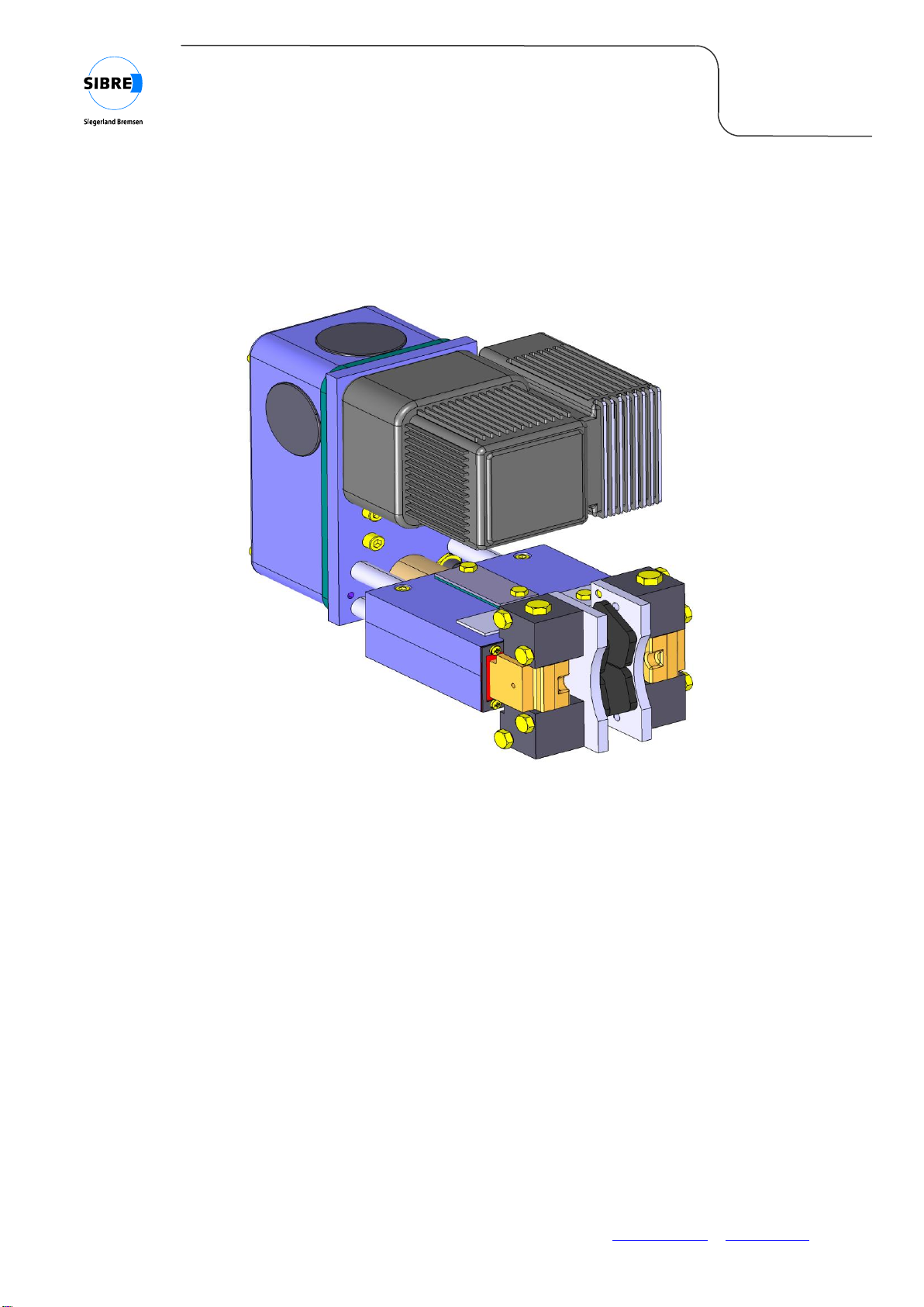
The CB8-E (see figure 1 and figure 2) is designed to transfer a braking torque to a brake disc in
order to stop the rotation of the brake disc or to prevent the brake disc from rotating when stopped
(parking brake). Any other use of the brake should be avoided.
CB8-E brakes are suitable for horizontal and vertical brake discs under any angular displacement.
The CB8-E is designed as a caliper brake which is activated / closed by the force of an integrated
helical compression spring. The clamping force and so the brake torque can be adjusted by adjusting
this spring force. An electro-hydraulic thrustor is used to open the brake.
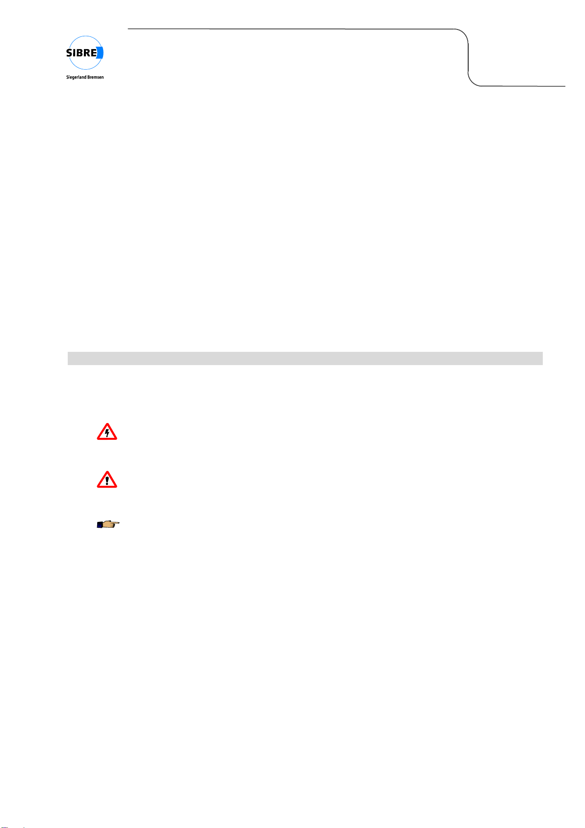
Fig. 1: CB8-E
brake lining
brake shoe
thrustor
protection
cover
housing
removable
cap
sensor
„pad wear”
B06 20 243 E-EN
page 6 / 23
09.2010
Installation and Maintenance Manual
CB8-E
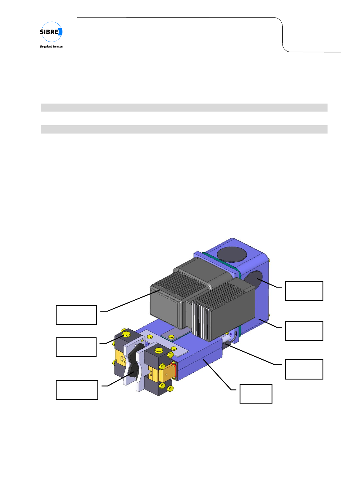
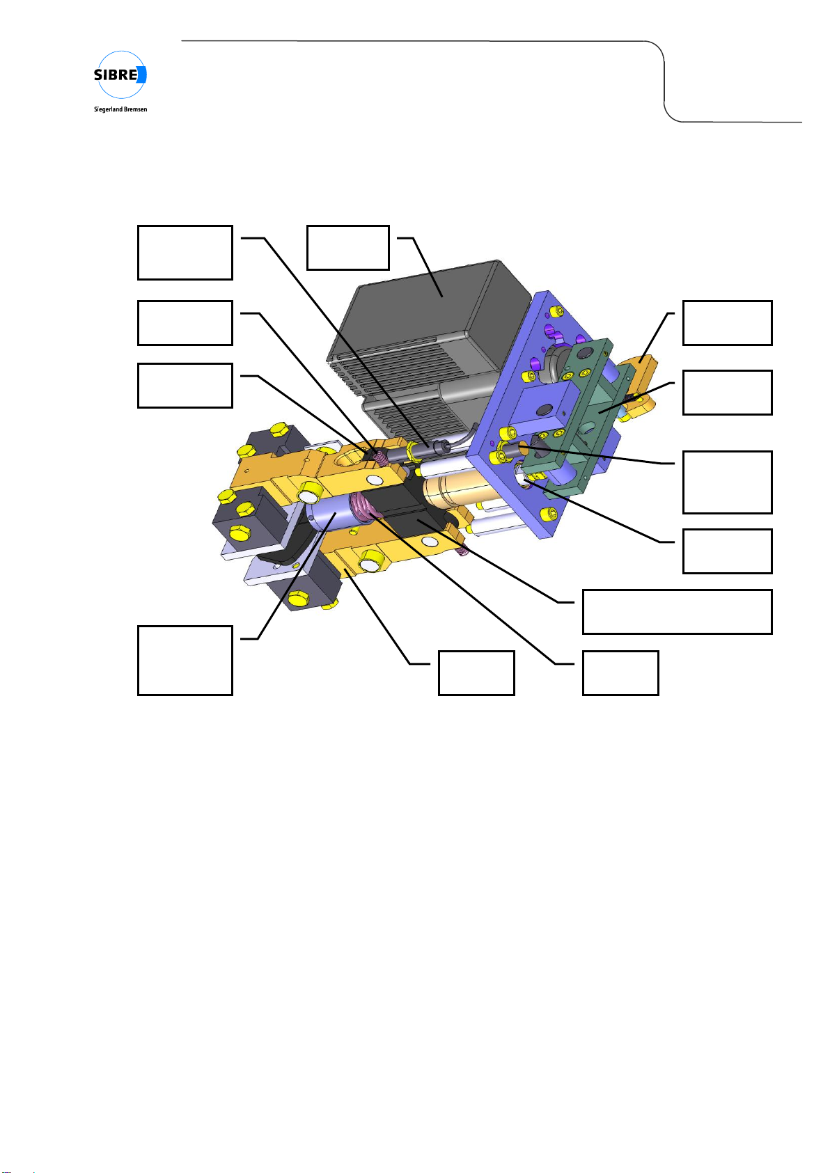
Fig. 2: CB8-E
The main components of the brake calliper are as follows:
Housing: The brake is mounted with three bolts M16 on a base frame or sub-construction.
Brake lever: Hinged with the brake shoes, they surround the brake disc and apply the braking
force. When releasing the brake, the embedded restoring springs lift the brake
shoes from the disc.
Thrustor: The thrustor is used to open the brake and is acting against the spring force. The
energy required for release is generated electro-hydraulically. The release force is
transmitted to the square part by the release lever and the stud.
Readjusting unit: The readjusting unit is used for compensation of lining wear, however its
compensating capacity per braking cycle is limited. Therefore an additional manual
wear compensation carried out by maintenance personnel is required according to
the specific application.
Spring: The helical compression spring generates the brake force and pushes the square
part back. The rollers transmit the brake force with low friction to the brake levers.
retension
spring
thrustor
square part with integrated
readjusting unit
spring
stud
sensor
„brake
open”
sensor
„pad wear”
release
lever
adjustable
spring
chamber
roller
manual
release
brake
lever

B06 20 243 E-EN
page 7 / 23
09.2010
Installation and Maintenance Manual
CB8-E
Spring chamber: Allows the continuous adjustment of spring torque, by adjusting the preload of the
spring.
Protection cover: The protection cover avoids the fouling of the release mechanism and guarantees
the operational reliability of the brake even under rough environmental conditions.
Removable caps allow the fast access to the manual release and enable the
maintenance personnel easily to control the reserve stroke.
Sensors: Sensors can be used to check the lining wear and to check if the brake is open.

B06 20 243 E-EN
page 8 / 23
09.2010
Installation and Maintenance Manual
CB8-E
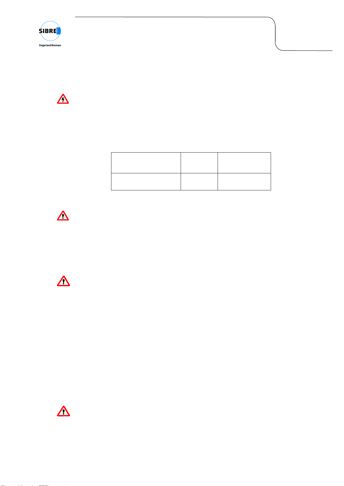
3.2 Dimensions
dimensions depending on selected lining size
ØD1
ØD3
R
H
CB8-M3-50 with lining size 50
ØD2 –46
ØD2 –110
ØD2 /2 + 19.5
120
CB8-M4-100 with lining size 100
ØD2 –60
ØD2 –140
ØD2 /2 + 15
170
Braking torque in Nm (µ = 0,4) on disc-Ø D2,
adjustable from / to
Ø 200
Ø 250
Ø 315
Ø 400
Ø 500
CB8-M3-50
80-300
110-400
140-530
180-700
n.a.
CB8-M4-100
n.a.
350-680
460-910
620-1220
800-1580
Fig. 3: Dimensions of CB8-E
Options protective cover, manual release, limit switches „brake open“ & „pad wear“
thrustor mounting position selectable between “L”, “T” or “R”
B = disc thickness in mm, Standard = 20, optional: 12.7; 16; 25; 30
ØD2 = outer disc diameter in mm
linings: = organic, size 50 (suitable for circum. disc speed vmax= 35 m/sec)
= sinter, size 100 (available for disc diameter ØD2 250)

B06 20 243 E-EN
page 9 / 23
09.2010
Installation and Maintenance Manual
CB8-E
4 Installation
4.1 Scope of supply
The scope of supply is set out in the shipping documents. Completeness must be verified upon
receipt. Any damage incurred in transit and/or missing parts must be reported immediately in writing.
The CB8-E brake is supplied ready to install.
4.2 Transport
When leaving the factory the brake is always packed in such a way to guarantee maximum security
during transport.
4.3 To be noted before installation
During installation comply with the safety directions in §2.
All work must be performed with care and with a focus on the safety aspect.
WARNING
Non-compliance with these directions can lead to malfunction of the brake.
WARNING
Safeguard the disc against inadvertent rotation!
4.4 Lifting and Handling
The CB8-E brake is to be handled with care. The weight of the brake is approx. 42 kg including
thrustor.
CAUTION
Ensure use of suitable lifting gear.
To avoid damaging component parts or paintwork do not place chains or wire around the
caliper when lifting.
In order not to damage any parts on the brake do not fit any hook, rope, chain or strap around
indicators, linings, etc.
B06 20 243 E-EN
page 10 / 23
09.2010
Installation and Maintenance Manual
CB8-E
4.5 Cleaning the brake disc
PLEASE NOTE
Before installing the brake the disc must be washed clean with white spirit and thereafter with
thinners or tricolour ethylene. Any residual oil or anti-corrosion reparation will reduce the
friction coefficient markedly.
WARNING
Solvent cleaners can be flammable, poisonous and can cause burns. To avoid serious
personal injury, read the manufacturer’s instructions carefully before using a solvent cleaner
and follow these instructions. Also wear eye protection, protective clothing and work in well-
ventilated areas.
4.6 Cleaning the mounting surfaces
PLEASE NOTE
The mounting surface for the base plate should be cleaned in a similar way as the brake disc.
WARNING
Solvent cleaners can be flammable, poisonous and can cause burns. To avoid serious
personal injury, follow the manufacturer’s instructions and see §4.5.
4.7 Handling of brake linings
The brake linings are an essential part of the brake system. They should be handled carefully to avoid
damages or soiling of the friction material.
CAUTION
Brake linings should be kept as clean as possible especially from any kind of grease and oil.
Even a small amount of oil can reduce the friction coefficient and cause a malfunction of the
brake.
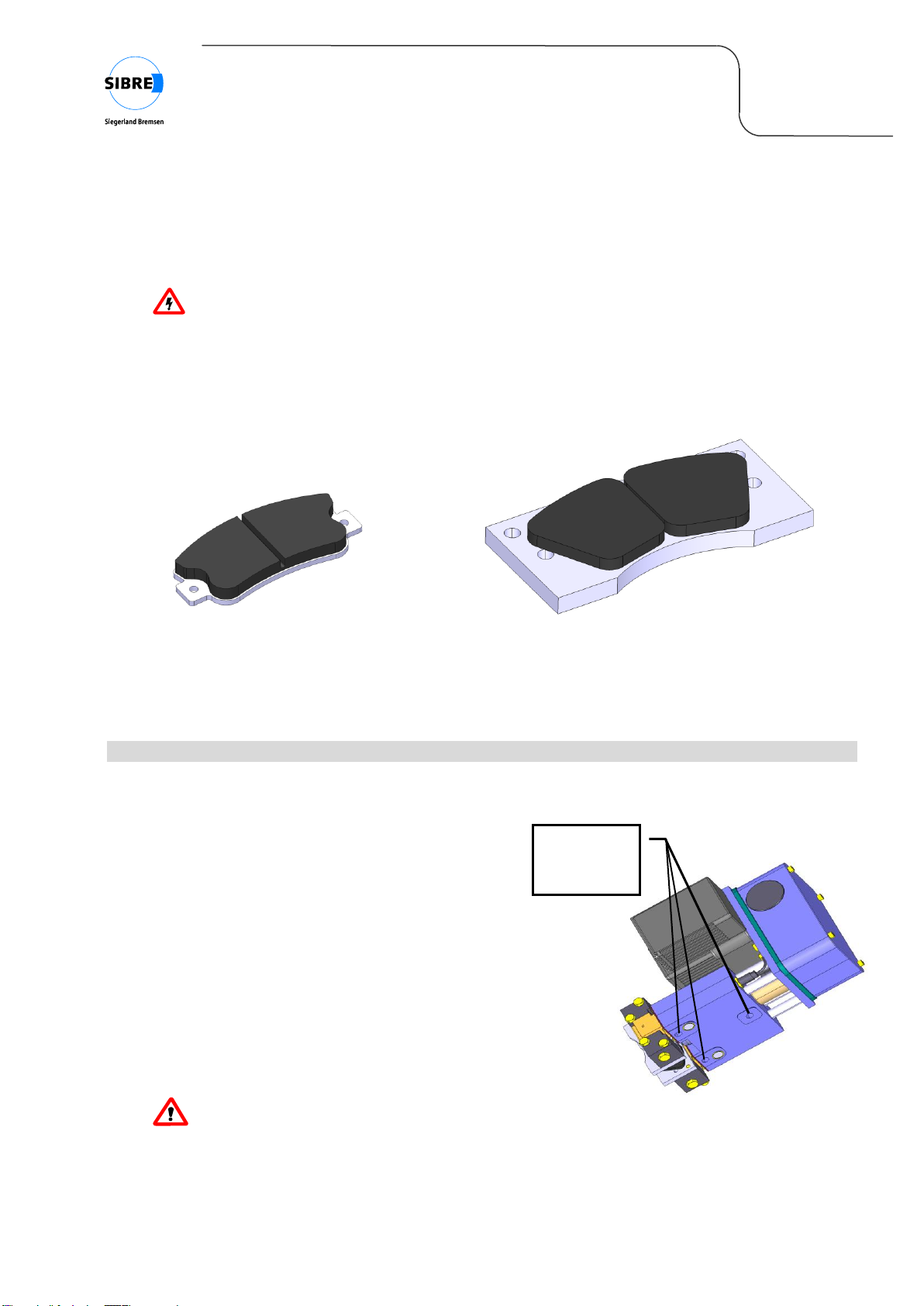
Brake linings can be supplied with several lining materials in two different types, depending on the
brake size and/or application. All brake linings supplied by SIBRE are asbestos free and free of lead.
In general two types of lining materials are available:
Organic brake linings size 50 for CB8-E-50
Sinter brake linings size 100 for CB8-E-100
CAUTION
Organic brake linings must be protected against grease and oil, which would significantly
decrease the friction coefficient. Cleaning of organic lining material is not possible. If any
grease or oil comes in contact with organic lining material, the lining must be discarded.
B06 20 243 E-EN
page 11 / 23
09.2010
Installation and Maintenance Manual
CB8-E
mounting
bolts
(3 x M16)
Sinter brake linings are less sensitive to dirt, grease and oil and can in some cases - where not fully
soaked up with oil - be cleaned with solvent and re-used.
WARNING
Solvent cleaners can be flammable, poisonous and can cause burns. To avoid serious
personal injury, follow the manufacturer’s instructions and see §4.5.
The different types of linings can be seen in figure 4.
a) organic lining size 50 for CB8-E-50 b) sinter lining size 100 for CB8-E-100
Fig. 4: Different types of brake linings for CB8
4.8 Mounting of the brake –initial setup on site
Ex works the gap between the lining surfaces is adjusted to the disc thickness the customer has
specified and fixed with a (wooden) distance piece.
The mounting of the brake should be done as
follows.
1. Open the brake with the help of the manual
release (see §4.9) and remove the distance
piece.
2. Put the brake on the sub-construction and
mount the three fastening bolts (figure 5).
Tighten the bolts only by hand in order to enable
the brake to centre itself when closing.
CAUTION
Choose bolt length so that bolts cannot jut inside
the housing and block the square part (max. overhang 14 mm).
3. Close the brake with the manual release. The brake will align automatically when closed.
Fig. 5: Mounting of CB8-E
B06 20 243 E-EN
page 12 / 23
09.2010
Installation and Maintenance Manual
CB8-E
WARNING
The manual release is spring biassed to realize an auto-kickback functionality. The activated
manual release will jump back in its initial position automatically by spring force, when the
brake is released by solenoid the next time.
4. Tighten fastening bolts when brake is closed.
Position of bolt
Bolt size
Tightening torque
(µG= 0.14)
Mounting bolts for
housing
M16 - 8.8
200 Nm
Fig. 6: Tightening torque for mounting bolts
CAUTION
The force transmission between the housing and the mounting surface should take place by
friction and not by the shear capacity of the mounting bolts. Therefore NO lubricant or other
compound must be applied between housing and mounting surface. The needed friction is
created by the clean, dry, lubricant free surface and by the accurate mounting of the bolts.
5. Connect the thrustor with the power supply.
CAUTION
Check the indications on the thrustor name plate before connecting it with the power supply.
6. Adjustment of brake torque:Check the installed brake torque. If necessary install the required
brake torque following the instructions in §4.11.
7. Adjustment of reserve stroke: The adjustment of the reserve stroke (see §4.10) is carried out
automatically by successive opening and closing the brake several times (approximately 40-50
cycles). Thus the readjusting unit sets the brake in working position.
8. Check by electronically opening of the brake, if the gap between brake linings and brake disc is
the same on both sides. Otherwise adjust the position of the brake. The permissible misalignment
for all brake axles is ± 0,1 mm
The brake is ready for operation now.
CAUTION
The brake linings and the disc must be free of oil and grease.
B06 20 243 E-EN
page 13 / 23
09.2010
Installation and Maintenance Manual
CB8-E
CAUTION
The full torque is only generated after bedding in of the linings. The contact pattern must be
minimum 70% for operation.
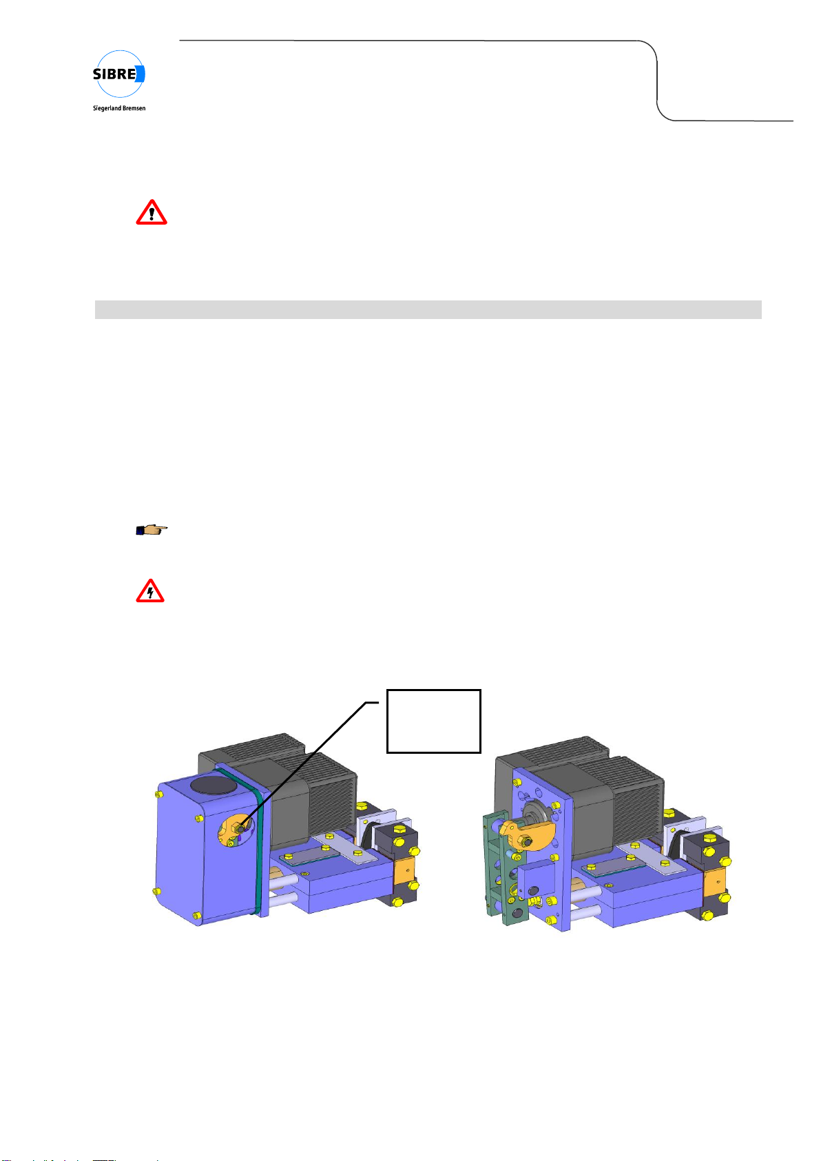
4.9 Manual release
The disc brake CB8 is provided with an eccentric manual release in series.
The handling of the manual release is carried out as follows:
1. Remove the sidewise cap (figure 7a)
2. Rotate the eccentric shaft clockwise until the indexed position is reached (figure 7b).
The brake is released now.
PLEASE NOTE
For the handling of the manual release a socket key wrench size 19 is recommended.
WARNING
The manual release is spring biassed to realize an auto-kickback functionality. The activated
manual release will jump back in its initial position automatically by spring force, when the
brake is released by solenoid the next time.
3. Push in sidewise cap.
a) Activating manual release b) Activated manual release, view without
protection cover
Fig. 7: Manual release
actuator for
manual
release

B06 20 243 E-EN
page 14 / 23
09.2010
Installation and Maintenance Manual
CB8-E
4.10 Adjustment of reserve stroke
The reserve stroke avoids, that the brake gets "on block" position and no more braking force is
transmitted to the disc any more. Without counteraction the reserve stroke would decrease with
increasing lining wear. Therefore the disc brake CB8-E is provided with an automatic readjusting unit
by default.
As the compensating capacity per braking cycle is limited, a regular inspection of the reserve stroke of
the closed brake is indispensable. Depending on the application a "manual" adjustment might be
necessary.
CAUTION
An insufficient or not existing reserve stroke may lead to a failure of the brake.
To check the reserve stroke remove the cap at the top of the protection cover. Push in the piston rod
of the thrustor manually against block. The reserve stroke can be measured between the roller of the
release lever and the piston rod with a feeler gauge or by eye (see figure 8). It must be approx. 7 mm.
Fig. 8: Checking the reserve stroke indirectly at the thrustor piston rod
Alternatively the reserve stroke can be controlled directly by removing the cover and the sealing at the
top of the brake housing. The distance between the square part and the housing can be measured
through the control window with a feeler gauge or by eye. It must be approx. 3 mm ( = 50% of control
window, see figure 9).
PLEASE NOTE
If the reserve stroke falls below, a "manual" adjustment has to be made by opening and
closing the brake against the stagnant disc until the required reserve stroke is reached again.
piston rod
roller

B06 20 243 E-EN
page 15 / 23
09.2010
Installation and Maintenance Manual
CB8-E
Fig. 9: Checking the reserve stroke directly at the square part
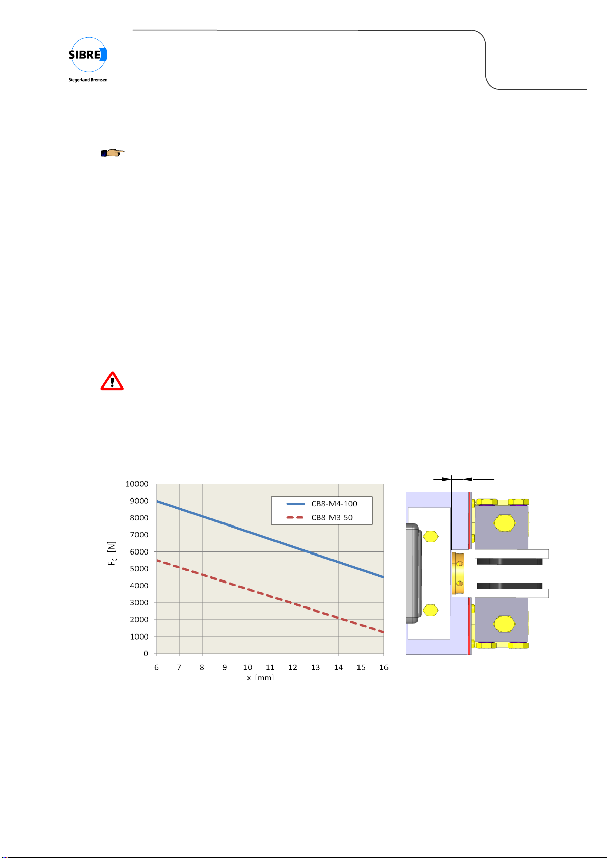
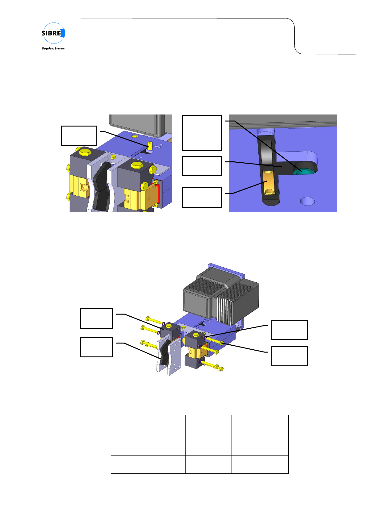
4.11 Adjustment of brake torque
The clamping force between the linings and the
disc and so the brake torque is created by a
helical compression spring.
The adjustment of the brake torque is done by
increasing or decreasing the spring preload
with the help of the adjustable spring chamber
(see figure 10 and figure 11).
Ex works the clamping force is already adjusted
to the brake torque the customer has specified
in his order. If there is no specification the
brake is adjusted to the minimum clamping
force. In this case the brake torque has to be
adjusted at site.
The adjustment of the brake torque is carried out as follows.
1. Calculate the braking torque MBr respectively the clamping force FC(see figure 3 for dimensions)
100-M4-CB8formm60-D
50-M3-CB8formm46-D
D0.4
D
M
FDFM 2
2
1
1
Br
C1CBr
2. Ascertain the required dimension x for the overhang of the adjustable spring chamber out of the
housing acc. to figure 11.
3. Turn around the spring chamber (figure 10 and figure 11) with a hexagon key Ø5 mm till the
ascertained overhang is reached.
cover with
sealing
control
window
square
part
adjustable
spring
chamber
Fig. 10: Adjustment of brake torque
B06 20 243 E-EN
page 16 / 23
09.2010
Installation and Maintenance Manual
CB8-E
PLEASE NOTE
Increasing the overhang will decrease the spring preload and so the clamping force / brake
torque.
Decreasing the overhang will increase the spring preload and so the clamping force / brake
torque.
4. Check and –if necessary –re-adjust the reserve stroke.
When the clamping force has been increased (overhang x has become smaller, figure 11) the
reserve stroke might have become too small for a safe functionality of the brake.
In this case the re-adjustment of the reserve stroke can be done by successive opening and
closing the brake several times (approximately 40-50 cycles). Thus the readjusting unit sets the
brake in working position.
When the clamping force has been decreased (overhang x has become bigger, figure 11) the
reserve stroke might have become too high. In this case proceed as described in §5.1 just
without replacement of the brake linings.
CAUTION
Changing the spring preload and so the clamping force might influence the existing reserve
stroke, too. Because of this a re-adjustment is absolutely necessary. An insufficient or not
existing reserve stroke may lead to a failure of the brake.
The brake is ready for operation now.
Fig. 11: Adjustment of brake torque
x
B06 20 243 E-EN
page 17 / 23
09.2010
Installation and Maintenance Manual
CB8-E
4.12 Limit switches
Optional the CB8 can be equipped with several kind of sensors.
“Pad wear”
An optional inductive limit switch (see figure 1 and figure 2) allows to detect lining wear. With
increasing lining wear the rotating angle of the two brake levers increases, too, when the brake is
closed. When the maximum allowed pad wear is reached, the brake lever will activate the limit switch
and a signal is send out. The sensor is chosen as “normally closed”, so that in case of a damage like
e. g. broken cable a signal is send out, too.
“Brake open”
An optional inductive limit switch (see figure 2) allows to control, if the brake is open. The sensor is
activated directly by the release lever. The sensor type “normally open” ensures, that in case of an
electronic or sensor defect there is no signal for “brake open”.
4.13 Removing the brake
1. Disconnect the thrustor from the power supply. Open the brake by using the manual release.
WARNING
The manual release is spring biassed to realize an auto-kickback functionality. The activated
manual release will jump back in its initial position automatically by spring force, when the
brake is released by solenoid the next time.
2. Unscrew the mounting bolts (3 x M16). The brake is now ready to be removed from the mounting
place.
WARNING
The weight of the brake is approx 42 kg including solenoid. Ensure use of suitable lifting gear.
3. Deactivate the manual release by hand.
WARNING
The manual release is spring biassed to realize an auto-kickback functionality.

B06 20 243 E-EN
page 18 / 23
09.2010
Installation and Maintenance Manual
CB8-E
5 Maintenance
5.1 Replacing the brake linings
CAUTION
When the linings are worn, they must be replaced. Worn out linings can cause a failure of the
brake.
The maximum allowed lining wear of 5 mm per side is reached, when the remaining thickness of the
lining has reached a value of 2 mm for sinter linings or 7 mm for organic linings. The brake pad
thickness can always be checked with a gauge. All brake linings for the CB8 consist of a steel back
plate and the friction material. The linings have a total thickness of 17 mm, i.e. linings must be
replaced when the thickness of friction material + back plate is minimum 12 mm.
The brake linings can be replaced without dismounting of the brake.
CAUTION
See §4.7 for proper handling of brake linings.
To replace the linings follow the below mentioned steps.
1. Ensure that the whole drive system is secured against unintentional movement.
WARNING
Prior to commencing any repair or other work, the owner must guarantee for a standstill of the
whole drive system. Especially the drive motors must be locked against unintentional
switching. Further we draw your attention to the specific rules for prevention of accidents of
the plant.
WARNING
Never place your fingers between the brake linings and the brake disc.
2. Remove cover and sealing from topside of housing (figure 9).
3. Turn the threaded pin out of the free wheel ring (figure 12).
4. Open the brake with manual release (see §4.9).
5. Turn around the adjusting nut (figure 12) with a hexagon key Ø4 mm in direction of brake disc
until block or until the distance between brake shoes and disc is wide enough to mount new
linings.
B06 20 243 E-EN
page 19 / 23
09.2010
Installation and Maintenance Manual
CB8-E
6. Turn the threaded borehole inside the free wheel ring into the upper position by pumping the
adjusting nut with the hexagon key Ø4 mm. Mount threaded pin (figure 12).
Fig. 12: Handling of the readjusting unit
7. Loosen the bolts for the brake linings on the brake shoes. The linings can be removed upwards,
downwards or in front direction (figure 13).
Fig. 13: Replacing the brake linings
8. Put new linings on the brake shoes and fix them with bolts and locking washers .
Position of bolt
Bolt size
Tightening torque
(µG=0.14)
Mounting bolts for
linings CB8-M3-50
DIN961-
M8x1x55 - 8.8
25 Nm
Mounting bolts for
linings CB8-M4-100
DIN 933
M10x60 - 8.8
50 Nm
Fig. 14: Tightening torque for mounting bolts
threaded
pin
adjusting
nut
free wheel
ring with
threaded
borehole
square
piece
mounting
bolt
brake
lining
piece
locking
washer
brake
shoe
piece
B06 20 243 E-EN
page 20 / 23
09.2010
Installation and Maintenance Manual
CB8-E
CAUTION
The force transmission between brake shoes and linings should take place by friction and not
by the shear capacity of the mounting bolts. Therefore NO lubricant or other compound must
be applied between brake shoe and lining carrier plate. The needed friction is created by the
clean, dry, lubricant free surface and by the accurate mounting of the bolts.
9. Adjust reserve stroke by successive opening and closing of the brake several times
(approximately 40- 50 cycles). Control reserve stroke.
CAUTION
An insufficient or not existing reserve stroke may lead to a failure of the brake.
10. Mount cover and sealing on topside of housing.
11. Bed in the new linings. The brake is ready for operation again.
CAUTION
The full torque is only generated after bedding in of the linings. The contact pattern must be
minimum 70% for operation.
5.2 Replacing other components
Although some minor components might be replaced with the brake mounted on site, generally it is
highly recommended to take the brake to a SIBRE workshop for repairs. For removing the brake
follow the instructions given in §4.13.
5.3 Lubrication
Lubrication is not required for this type of brake. All bearings are equipped with self-lubricating
bushings and so virtually free of maintenance.
This manual suits for next models
2
Table of contents


