SIC 2000 User manual
Manuale utente
User’s manual
Mode d’emploi
Betriebsanleitung

E’ IMPORTANTE PER LA SICUREZZA VOSTRA E
DELLE APPARECCHIATURE UNA ATTENTA LETTURA
DELLE PRESCRIZIONI E NORME DI SICUREZZA
CONTENUTE NEL MANUALE UTENTE
IT IS VERY IMPORTANT FOR THE
EQUIPMENTS AND YOUR SAFETY TO CAREFULLY
READ THE SECURITY RULES SHOWN IN THIS
INSTRUCTION MANUAL
IL EST IMPORTANT POUR VOTRE SECURITE’
ET DES VOS APPAREILS UNE LECTURE ATTENTIVE
DES PRESCRIPTIONS ET DES NORMES DE
SECURITE’ CONTENUES DANS LE MODE D’EMPLOI
IM INTERESSE IHRER PERSOENLICHEN
SICHERHEIT UND DEREN DES GERAETES IST ES
SEHR WICHTIG, DIESE BETRIEBSANLEITUNG
SORGFAELTIG DURCHZULESEN
I
GB
F
D

Indice
Introduzione alla consultazione del manuale utente del tester SIC 2000 pag. 2
Norme generali – Avvertenze pag. 3
Alimentazione – Protezione elettrica pag. 4
Legenda pag. 5
Dati tecnici e funzione tester SIC 2000 pag. 6
Utilizzo del tester SIC 2000 pag. 7
Dichiarazione di conformità pag. 11
Index
Introduction to the consultation of the instruction manual of tester SIC 2000 page 2
General rules – Warning page 3
Feeding, electric protections page 4
Legenda page 5
Technical data and fonctions of tester page 6
Use of tester SIC 2000 page 8
Conformity declaration page11
Index
Introduction à la consultation du mode d’emploi du tester SIC 2000 page 2
Consignes de securité et d’utilisation page 3
Alimentation – Protection page 4
Legenda page 5
Données téchniques et fonction du tester SIC 2000 page 6
Emploi du tester SIC 2000 page 8
Déclaration de conformité page11
Inhaltsverzeichnis
ANWEISUNGEN UND BERATUNG ÜBER DIE
BETRIEBSANLEITUNG DES TESTERS SIC 2000 Seite 2
Vorsichtsmassnahmen und Gebrauch Seite 3
Versorgung und Schutz der Elektrik Seite 4
Bilderklärung Seite 5
Technische Daten Seite 6
Funktionen des Testers SIC 2000 Seite 8
Übereinstimmungs-Deklaration Seite 11
- 1 -
F
I
D
INTRODUZIONE ALLA CONSULTAZIONE DEL PRESENTE MANUALE
UTENTE DEL TESTER SIC 2000
E’ indispensabile leggere con attenzione ogni singolo paragrafo di questo manuale per evitare
qualsiasi incidente a persone o cose e per sfruttare al massimo le possibilità di lavoro offerte dal
tester SIC 2000 senza influire negativamente sull’efficienza e sulla durata dello strumento in Vs.
possesso.
Qualora sorgessero dubbi sull’interpretazione delle spiegazioni illustrate su questo manuale Vi
consigliamo di non prendere iniziative ma di contattare il rivenditore che sarà ben lieto di assisterVi
prontamente e chiarire ogni incertezza. I paragrafi che trattano di operazioni dove è implicita una
certa dose di pericolo per l’operatore saranno preceduti dal simbolo :
ATTENZIONE
Tenere sempre il manuale a portata di mano e consultatelo attentamente per imparare a maneggiare
lo strumento con sicurezza.
INTRODUCTION TO THE CONSULTATION TO THE INSTRUCTION
MANUAL OF TESTER SIC 2000
Please read carefully every paragraph of this manual to avoid any personal injury or property
damage and to take full advantage of the use of tester SIC 2000.
If you have any doubts regarding the instructions shown in this manual, please contact your dealer
before using the equipment.
The following symbols indicate potential hazards to the operator.
WARNING
Always keep this manual to hand and refer to it when using the equipment.
INTRODUCTION A LA CONSULTATION DU MODE D’EMPLOI DU TESTER
SIC 2000
Il est indispensable de lire avec attention chaque paragraphe de ce mode d'emploi afin d'utiliser au
mieux les possibilités de ce tester et d'éviter les accidents matériels et corporels.
Lorsque Vous avez des doutes sur l'intrerprétation des explications de cette notice, nous Vous
conseillions de ne pas prendre d’initiative mais de contacter le service téchnique.
Les paragraphes qui traitent des opérations dangereuses pour l’opérateur seront précédés par le
symbole :
ATTENTION
Conserver toujours ce mode d’emploi et consulter-le avec soin pour apprendre à utiliser l’apparéil
avec sureté.
METHODE, ANWENDUNG UND BETRIEBSANLEITUNG DES TESTERS SIC
2000
Wir bitten Sie, jeden Paragraph dieser Betriebsanleitung sorgfältig durchzulesen. Vermeiden Sie
Missbrauch und unsachgemässe Behandlung, welche zu Personen- oder Sachschäden führen
können. Bei eventueller Unklarheit, konsultiere Sie bitte vorgängig die Betriebsanleitung oder den
technischen Dienst des Importeurs.
Das nachfolgende Symbol weist auf potentielle Gefahren für den Anwender hin.
WARNUNG
Beim Gebrauch des Testers, behalten Sie diese Betriebsanleitung immer in Ihrer Nähe.
- 2 -
I
GB
F
D

NORME GENERALI -
Avvertenze
L’uso di quest’apparecchio, come qualsiasi operazione in campo motoristico, deve essere effettuata
da personale specializzato che conosca e rispetti le norme tecniche ed antinfortunistiche del caso al
fine di evitare ogni possibile danno a persone o cose. La temperatura ambientale e l’umidità relativa
non dovranno eccedere i seguenti valori limite:
per il funzionamento normale in officina: temp.minima 0°C (32°F) massima 35°C(95°F)
Umidità relativa massima 80% con temperatura ambiente minore o uguale a 20°C (68°F) per la
conservazione in magazzino: temp.min. –15°C (6,8°F) massima 65°C (149°F)
Umidità relativa massima 50% con temperatura ambiente compresa tra 20 e 60°C (68 e 140°F)
La massima concentrazione ammessa per la polvere ambientale è di 0,1 grammi/metro³ Non
sottoporre lo strumento ad urti violenti, a temperature elevate, ad umidità o a forti campi
elettromagnetici. La pulizia dello strumento deve essere effettuata con panni asciutti non abrasivi
oppure con panni morbidi moderatamente imbevuti di detergente liquido adatto a superfici plastiche.
NON DEVONO UTILIZZARE L’APPARECCHIO:
i portatori di pace-maker; le persone con inadeguate conoscenze tecniche; le persone in condizioni
psicofisiche non ottimali o sotto l’influenza di alcool, droghe e psicofarmaci.
GENERAL RULES -
Warning
This equipment must be only used by trained personnel, adhering to these instructions to avoid any
possible damage to personnel or property.
The ambient temperature and the relative humidity should not be over the following values. For the
normal working in workshop: min. temperature 0°C (32°F) – max. temperature 35°C (95°F)
max relative humidity 80% with ambient temperature less or equal to 20°C (68°F)
for the storage:min. temperature -15°C (6,8°F) – max. temperature 65°C (149°F)
max relative humidity 50 % with ambient temperature between 20°and 60 °C (68°and 140°F)
Max allowable ambient concentration for dust is 0,1 gr/m squared.
Do not subject the equipment to shocks, to excessive temperatures, moisture or electro-magnetic
fields. To clear the equipment do not use abrasive cloths or substances. Clean with a soft cloth
slightly moistened with liquid detergent or a cleaner suitable for plastic surfaces.
THE EQUIPMENT SHOULD NOT BE USED BY:
Any person fitted with a pacemaker; any person without sufficient technical knowledge and
experience; any person under the influence of alcohol and drugs.
NORMES GENERALES -
Avvertissements
Afin d'éviter des dommages matériels et corporels, l'utilisateur de cet apparéil, comme pour toutes les
interventions sur les moteurs thermiques, doit être une personne qualifiée qui connaît et respecte les
normes téchniques. La température ambiante et l'humidité relative ne devront être différentes des
valeurs ci-après. Pour un fonctionnement normal en atelier: température mini O°C (32°F) -
Température maxi 35°C (95°F) Humidité relative maxi: 80% avec température ambiante inférieure u
égale à 20°C (68°F) Pour le stockage: Témperature mini –15°C (6.8°F) - Témperature maxi 65°C
(149°-F) Humidité relative maxi 50% avec témperature ambiante entre 20°'et 60°'C (68°et 140°'F). Le
maximum accepté pour la poussière ambiante est de 0,1 gr./m³'Ne pas soummettre l'apparéil à des
chocs violents, à des témperatures très élévées, à l'humidité ou à des forts champs
éléctromagnétiques. Le nettoyage de cet apparéil devra être effectué avec des chiffons bien secs,
non abrasifs ou avec des chiffons souples un peu mouillés, et avec des détergents liquides indiqués
pour surfaces plastiques.
LES PERSONNES SUIVANTES NE DOIVENT PAS UTILISER LE TESTER
Ceux qui portent un pace-maker ; ceux qui n'ont pas des connaissances téchniques
approfondites ;ceux qui ne se trouvent pas en bonnes conditions physiques ou qui sont sous
l'influence ce l'alcool ou des médicaments.
-3 –
I
GB
F

VORSICHTSMASSNAHMEN UND GEBRAUCH
Zur Vermeidung von Personen- und Sachschäden darf dieses Gerät nur durch geschultes Personal
verwendet werden. Die Umgebungstemperatur und die relative Luftfeuchtigkeit darf nachstehende
Werte nicht über- oder unterschreiten.
Beim Betrieb des Testers darf die Raumtemperatur 0°C nicht unterschreiten, bzw. 35°C nicht
überschreiten. Die max. Luftfeuchtigkeit darf 80% bei einer Raumtemperatur von 20°C nicht
überschritten werden.
Bei Einlagerung des Gerätes sollte die Raumtemperatur -15°C, bzw. max 65°C nicht unter- oder
überschritten werden. Die max. Luftfeuchtigkeit von 50% sollte bei einer Raumtemperatur zwischen
20°C – 60°C nicht überschritten werden.
Die Staubdichte im Arbeitsraum darf 0.1 gr./m3 nicht überschreiten.
Vermeiden Sie extreme Temperaturschwankungen und elektromagnetischen Schocks. Bei
Nichtgebrauch, das Geräte mit feuchtem Tuch reinigen und mit einer Plastik-Hülle abdecken, bzw.
Koffer schliessen.
DAS GERÄT DARF NICHT GEBRAUCHT WERDEN:
Von Personen mit einem Herzschrittmacher oder Personal mit unzureichenden Fachkenntnissen und
–Erfahrungen. Ferner von Personen mit Drogen- und/oder Alkohol-Einflüssen.
ALIMENTAZIONE – PROTEZIONE
PROTEZIONI ELETTRICHE
Lo strumento riceve e trasmette impulsi in alta tensione o comunque di tensioni che possono essere
pericolose. Non effettuare nessuna operazione sui cavi di collegamento quando lo strumento sta
effettuando una qualsiasi operazione.
ATTENZIONE
L’Alta Tensione può provocare l’accumulo di elettricità statica su superfici isolate da terra. Controllare
sempre lo stato di usura dei vari cavi che non devono essere logori, tagliati o bruciati, in caso
contrario staccare l’interruttore generale, staccare la spina e rendere inutilizzabile lo strumento
tranciando il cavo di alimentazione. Informate l’assistenza per la sostituzione delle parti.
FUSIBILE - STACCARE LA SPINA PRIMA DI SOSTITUIRE IL FUSIBILE
Il fusibile è una protezione: la sua bruciatura indica un qualche malfunzionamento dello strumento.
Non sostituire il fusibile con uno di tipo avente caratteristiche diverse da quello specificato. Chiamare
l’assistenza per una verifica se il fusibile brucia frequentemente.
CARATTERISTICHE DEL FUSIBILE: L’impianto elettrico della macchina è protetto da un solo
fusibile Procedura per la sostituzione:Disinserire la spina di alimentazione Svitare in senso
antiorario il cappuccio.Estrarre il fusibile e sostituirlo con uno di eguale portata e dimensione:T500
mA 250V 5x20 rispondente alle normative IEC 127 III Riavvitare in senso orario il cappuccio.
Reinserire la spina.
FEEDING AND PROTECTION
ELECTRIC PROTECTIONS
The device receives and transmits H.T. impulses or impulses which can be dangerous. Do not work
on connecting cables when the device is working.
WARNING The High Tension can generate static electricity accumulation on surfaces insulated from
the ground. Always check the cables wear condition. They must not be weared, cut or burned. On
the contrary, disconnect the general switch, disconnect the plug and make the device unusable by
cutting the feeding cable. Call assistance people for the parts replacement.
FUSE - DISCONNECT THE PLUG BEFORE REPLACING FUSE
The fuse is a protection : its burning shows bad working of the device Do not replace fuse with one of
different features. Call assistance people if fuse often burns.
FUSE FEATURES: The electrical plant of the device is protected by one only fuse.
Replacement instructions: Disconnect feeding plug. Unscrew anticlockwise
Take fuse away and replace it with one of the same range and dimensions type : T500 mA 250V
5X20 according rules IEC 127 III. Screw clockwise cap. Connect the plug.
- 4 -
I
GB
D

ALIMENTATION ET PROTECTION
PROTECTION ELECTRIQUES
L’apparéil réçoit et transmet des impulsions en haute tension ou de tensions qui peuvent être
dangereuses. Ne pas effectuer des opérations sur les câbles de branchement quand l'apparéil est
en train d'effectuer n'importe quelle opération.
ATTENTION
L’Haute Tension peut causer le cumul d'électricité statique sur des surfaces isolées de terre.
Contrôler toujours la condition d'usure de tous les câbles qui ne doivent pas être coupés ou brûlés.
En cas contraire éteindre l'apparéil, détacher la fiche et rendre l'apparéil inutilisable en coupant le
câble d'alimentation. lnformer l'assistance pour le remplacement des pièces
FUSIBLE - DETACHER LA FICHE AVANT DE REMPLACER LE FUSIBLE
Le fusible est une protection; sa brûlure indique un mauvais fonctionnement de l'apparéil. Ne pas
remplacer le fusible avec un fusible ayant des caractéristiques différentes de celui original. Appeler
l'assistance pour un contrôle si le fusible brûle souvent.
CARACTERISTIQUES DU FUSIBLE L’installation électrique de l'apparéil est protegée par un seul
fusible. Instructions pour le remplacement: Détacher la fiche d'alimentation. Dévisser le capuchon
dans le sens contraire du celui des aiquilles d'une montre. Enlever le fusible et le remplacer avec un
T 500 mA 250 V 5x20 repondant à les règles IEC 127 III. Révisser le capuchon dans le sens des
aiguilles d'une montre. Réinsérer la fiche d'alimentation.
VERSORGUNG UND SCHUTZ DER ELEKTRIK
Die Vorrichtung erhält und übermittelt Hochspannungs-Impulse (H.T.) welche gefährlich sein können.
Nicht mit Übertragungskabel arbeiten, wenn die Vorrichtung im Betrieb ist.
WARNUNG: Die Hochspannung kann allgemein statische Elektrizität vom Grund auf isolierten
Oberflächen aufbauen. Überprüfen Sie alle Kabel immer auf defekte, gebrochene, verschnittene,
verbrannte Isolierungen. Bei vorgenannten Ereignissen das Gerät unverzüglich ausschalten und den
Anschlussstecker vom Stromnetz ausziehen. Lassen Sie das Gerät unverzüglich vom Importeur
überprüfen.
SICHERUNG: VOR DEM AUSWECHSELN ODER PRÜFEN DER SICHERUNG IMMER DEN
NETZSTECKER VORGÄNGIG AUSZEIHEN!
Die Sicherung vermeidet Kurzschlüsse und Brände und sichert die Vorrichtung.
MERKMALE DER SICHERUNG: Elektrogeräte und deren Vorrichtung sind nur mit einer Sicherung
abgesichert.
Austausch der Sicherung: Netzstecker ausziehen. Deckel im Gegenuhrzeiger-sinn ausschrauben,
defekte Sicherung herausnehmen, neue Sicherung T160 mA/250V/5x20 gem. Regel IEC 127 III
montieren. Schutzdeckel im Uhrzeigersinn aufschrauben und Netzstecker wieder einstecken.
- 5 -
F
D

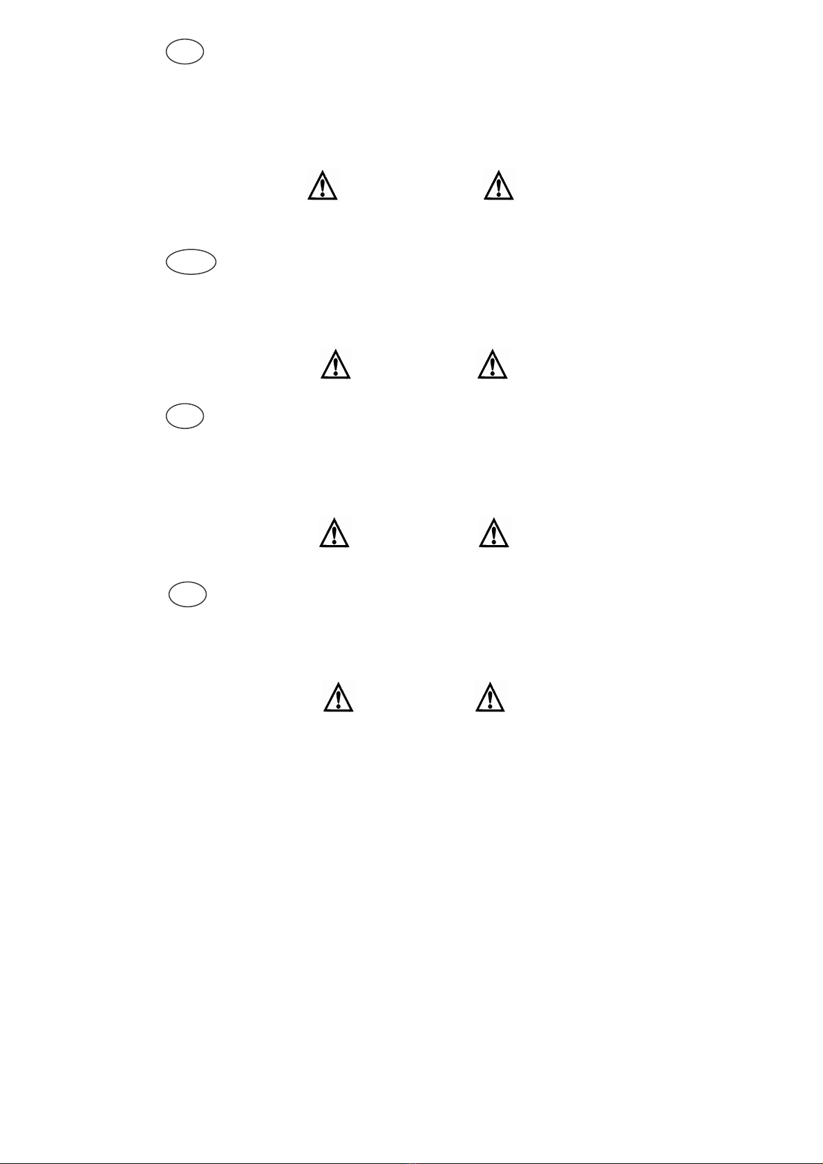
LEGENDA
01. Cavo alimentazione 01. Feeling cable 01. Câble alimentation
02. Cavo ingresso A.T. 02. Input H.T. cable 02. Câble entrée H.T.
03. Cavo candela out A.T. 03. Output H.T. cable 03. Câble bougie sortie HT
04. Cavo rosso/nero per
prova bobina A.T. 04. Red/black cable for H.T.
coil test 04. Câble rouge/noir pour
essai bobine H.T.
05. Lampada stroboscopica
05. Stroboscopic lamp 05. Lampe stroboscopique
06. Tasto prova bobina AT 06. H.T. coil test button 06. Interrupteur pour l’essai
de la bobine H.T.
07. Tasto prova con
motore in moto 07. Engine running test button
07. Interrupteur pour l’essai
avec moteur en marche
08. Presa lampada
stroboscopica 08. Stroboscopic lamp plug 08. Prise pour lampe
stroboscopique
09. Tasto ON 09. ON button 09. Interrupteur ALLUME’
10. Tasto OFF 10. OFF button 10. Interrupteur ETEINT
11. Lampada accensione
buona 11. Good ignition system
warning light 11. Témoin lumineux
signalant allumage bon
12. Lampada OK 12. OK lamp 12. Tèmoin lumineux OK
13. Lampada accensione rotta
13. Faulty ignition system
warning light 13. Témoin lumineux
signalant allumage
mauvais
14. Lente spinterometro 14. Spark gap lens 14. Spinteromètre
15. Manopola regolazione
spinterometro 15. Spark gap adjustment
knob 15. Bouton regulation
du spinteromètre
F
GB
I

DATI TECNICI/TECHNICAL DATA/DONNEES TECHNIQUES
TIPO/TYPE/TYPE SIC 2000
MODELLO/MODEL/MODELE 132.000
ALIMENTAZIONE/ALIMENTATION/FEEDING 230 V~ 50 Hz
POTENZA/POWER/PUISSANCE 40 V.A.
DIMENSIONI/DIMENSIONS/DIMENSIONS 338 x 205 x 97
MASSA/WEIGHT/POIDS 4400 gr.
GRADO DI PROTEZIONE/PROTECTION
DEGREE/DEGRE’ DE PROTECTION
IP 40
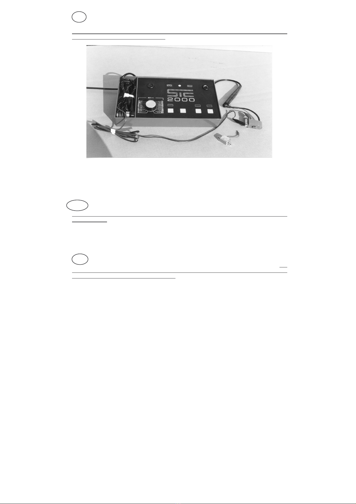
FUNZIONE
Il tester SIC 2000 permette di verificare il corretto funzionamento delle accensioni equipaggianti i
motori a ciclo Otto. L’impiego riguarda generalmente i motori utilizzati in agricoltura e similari.
La misura dell’Alta Tensione generata dall’accensione viene misurata tramite uno spinterometro
variabile, nel contempo al motore viene fornita alta tensione generata da un’accensione interna al
tester. Vari circuiti di controllo permettono inoltre di verificare sia la presenza dell’alta tensione sia la
regolarità dei tempi.
Il tester è inoltre dotato di cavi per il controllo della bobina A.T. e può essere dotato di lampada
stroboscopica per la verifica dell’anticipo.
FONCTION
The tester SIC 2000 allows the good working conditions of ignition systems assembled on gasoline
engines. Generally it is used on agricultural engines and similar. The H.T. value generated by the
ignition system is measured by a variable spark gap, in the same time the H.T. generated by an
ignition system inside the tester is supplied to the engine. Many checking circuits allow the test of
both H.T. presence and the time regularity. Finally the tester is supplied with cables checking A.T.
coil and with a stroboscopic lamp checking the advance.
FONCTION
Le tester SIC 2000 permet de contrôler l’exact fonctionnement des allumage électroniques montés
sur les moteurs à cycle Otto. En générale il est employé sur les moteurs agricoles et similaires.
Le mesure de l’Haute Tension produite par l’allumage est mésurée à travers un éclateur variable,
dans le même temps l’Haute Tension produite par un allumage intérieur au tester est fournie au
moteur. Plusieurs circuits de contrôle permettent enfin de vérifier soit la présence de l’Haute Tension
et soit la régularité des temps.
Le tester est aussi fourni avec des câbles pour le contrôle de la bobine H.T. et il peut être vendu
avec l’option d’une lampe stroboscopique pour contrôler l’avance.
- 6 -
GB
F
I

UTILIZZO
L’utilizzo del tester SIC 2000 è molto semplice; di seguito si trovano le normali procedure per i
controlli
CONTROLLO ACCENSIONI
1. Sconnettere il cappuccio candela e connetterlo al cavo ingresso A.T. del tester proteggendo la
giunzione con l’apposito cappuccio di gomma.
2. Collegare il cavo candela del tester alla candela del motore e verificare che ci sia un buon
collegamento della carcassa del motore con la molla del cappuccio.
3. Posizionare la manopola 2 sul valore minimo.
4. Accendere il tester premendo il pulsante START. Si devono illuminare la spia di rete e quelle di
controllo.
5. Effettuare l'avviamento del motore. Se la spia OK si accende, il motore si deve avviare. In caso
contrario, la causa del mancato avviamento andrà ricercata al di fuori dell'impianto di
accensione. In queste condizioni il tester fornisce alla candela una tensione capace di far
scoccare una scintilla di notevole potenza. A motore avviato, si deve illuminare la spia verde e
scoccare la scintilla tra le punte dello spinterometro.
6. Ruotare la manopola verso destra fino a quando la spia verde si spegne e la spia rossa si
accende stabilmente. In queste condizioni i KVolts letti sulla scala della manopola sono quelli
forniti dell'impianto di bordo del motore. Dal confronto di questo valore con quello dichiarato dal
Costruttore, si stabilisce il grado di bontà dell'accensione. Quando mancano i dati del
Costruttore, a titolo informativo, si tenga presente il seguente procedimento.
-valori misurati superiori a 10 KV : accensione buona
-valore massimo misurato 4 KV : accensione difettosa
-funzionamento regolare del motore S O L A M E N T E con il tester colleqato e valori
inferiori a 10 KV: accensione difettosa
-funzionamento regolare del motore sia con che senza tester e valori misurati compresi fra
6 e 20 Kv: accensione buona.
- 7 -
I

USE
The use of SIC 2000 tester is very simple; following you will find the normal checks
procedures.
IGNITIONS TEST
1. Disconnect the spark plug cap and connect it to H.T. input cable of the tester protecting
connection with the special rubber cap.
2. Connect spark plug of the tester to the spark plug of engine and check there is a good
connection between the engine frame and the cap spring.
3. Place knob on min. value.
4. Switch the SIC 2000 on pressing switch START. The START warning light and check warning
lights must appear.
5. Start the engine. If OK lamp switches on, the engine must start. lf not, the engine fault is not
due to bad electronic ignition. (Reason : tester itself gives enough tension to spark ). In these
conditions the tester supplies to the spark a tension able to produce a great powerful spark.
When engine is running, the green warning light must be on and spark should appear between
the spark gap points.
6. Turn knob right side until the green warning light goes out and the red warning light lights on
permanently. Under these conditions the KVolts reading on knob scale are those given by the
engine unit. Comparing this value with value stated by the engine Manufacturer you can state
the level of the good quality of the ignition. When Manufacturer's data are not available you have
to keep in mind the following procedure:
-values higher than 10 KV : good ignition
-max measured value 4 KV . faulty ignition
-regular engine working ONLY with tester connected and values lower than 10 KV: faulty
ignition
-
regular engine working both with and without tester and measured values between 6 and
20 KV : good .
EMPLOI
L’emploi du tester SIC 2000 est très simple ; Vous trouverez ci-dessous les
normales procédures pour les contrôles.
ESSAI DE L’ALLUMAGE
1. Déconnecter le capuchon de la bougie et le rélier au câble H.T. d’entrée du tester en protégeant
la connection avec le capuchon en caoutchouc.
2. Rélier le câble bougie du tester à la bougie du moteur.
3. Tourner le bouton sur la valeur min. et allumer l’apparéil en pressant le poussoir START. Le
témoin d’allumage en correspondance du START et ceux de contrôle doivent s’allumer.
4. Tirer le cordon du lanceur. Si la lampe OK s’allume, le moteur doit démarrer. Si le moteur ne
démarre pas le défaut n’est pas sur l’allumage et il faudra le chercher ailleurs (car l’apparéil
envoie à la bougie une tension suffisante à provoquer un’étincelle très puissante). En ces
conditions le tester fournit à la bougie une tension en mesure de faire éclater un’étincelle de
grande puissance. Quand le moteur est en marche, la lampe verte doit s’allumer et on verra
l’étincelle se produire sur le spinteromètre.
5. Tourner le bouton vers droite jusque le témoin vert s’éteigne et le témoin rouge s’allume
stablement. En cette conditions les Kvolts relévés sur l’échelle autour de la poignée sont ceux
fournis par l’installation du moteur. En comparant cette valeur avec les données mentionées par
le fabricant on établit le niveau de la bonne qualité de l’allumage. En cas de non possession
d’un tableau des valeurs du fabricant, aux fins d’une orientation, il faut tenir compte de la
suivante procédure :
-valeurs mesurées superieures à 10 KV : allumage OK
-valeurs max. mesurée 4 KV : allumage défectueux
-fonctionnement regulier du moteur SEULEMENT avec le tester branché et valeurs
inferieures à 10 KV : allumage défectueux
- fonctionnement regulier du moteur soit avec que sans tester et valeurs mesurées entre
6 et 20 KV : allumage OK
- 8 -
GB
F
PROVA DELLA BOBINA A.T. SMONTATA
ATTENZIONE: E’ importante controllare solo ed esclusivamente bobine A.T.
Gli apparati di accensione composti da un singolo modulo montati dalla maggioranza dei costruttori
non sono semplici bobine Alta Tensione e pertanto possono essere controllati solamente con
l’utilizzo di apparecchiature magnetiche.
1. Connettere il morsetto nero del cavo rosso/nero alla massa od al filo di massa della bobina,
quando questo risulta isolato dal nucleo metallico. Il morsetto rosso al filo attivo della bobina.
2. Connettere il filo A.T. della bobina al cavo collegamento al cavo candela del tester.
3. Accendere il tester premendo il tasto START e successivamente il tasto della prova bobina AT
4. Ruotare la manopola del tester fino a fondo scala. La spia luminosa verde deve rimanere accesa
per valori superiori ai 10 KV.
DISASSEMBLED H.T. COIL TEST
WARNING : It is important to check only and exclusively H.T. coils.
The ignition plants composed by one only module assembled by the most of Manufactuers are not
simple H.T. coils and therefore they can only be tested by magnetic devices.
1. Connect the black terminal of black/red cable to the ground point or the coil ground when
isolated from metallic core. The red terminal of cable to the active wire of the coil.
2. Connect H.T. cable of the coil to the spark plug cable connecting cable of the tester.
3. Switch the tester on pressing START switch and then H.T. coil test button switch.
4.
Turn knob of tester till the end of the scale. The green warning light must stay on for values
higher 10 KV.
ESSAI DE LA BOBINE H.T. DEMONTEE
ATTENTION: Il est important contrôler seulement et exclusivement les bobines H.T. Les
installations d’allumage composées par un single module et montées par la pluspart des
Constructeurs ne sont pas simple bobines H.T. e pourtant elles peuvent être contrôlées seul avec
l’emploi des apparéils magnétiques.
1. Relier la borne noire du câble rouge/noir à la masse ou au fil de masse de la bobine, quand
celui-ci est isolé du noyau métallique. La borne rouge au fil actif de la bobine.
2. Relier le fil H.T. de la bobine au câble à relier au capuchon de bougie de l’apparéil.
3. Allumer l’apparéil en pressant le poussoir START et presser l’interrupteur pour l’essai de H.T. de
la bobine.
4. Tourner la poignée jusqu’au fond de l’échelle. Le témoin lumineux vert doit rester allumé pour
valeurs superieures à 10 KV. - 9 -
I
GB
F
CONTROLLO DELL’ANTICIPO AUTOMATICO
1. Inserire lo spinotto della lampada stroboscopica nella presa relativa del tester.
2. Collegare il cavo candela del motore al cavo ingresso A.T. del tester ed il cavo
collegamento alla candela del tester sulla candela.
3. Accendere il tester premendo il pulsante START ed avviare il motore.
4. Orientare il fascio luminoso prodotto dalla lampada sul volano del motore.
ADVANCE TEST
1. Place lamp plug into the stroboscopic lamp plug of the tester.
2. Connect spark plug cable of the engine to H.T. input cable of tester and spark plug
connecting cable of tester to the spark plug.
3. Switch the tester on pressing START switch and start the engine.
4. Direct lamp’s light on flywheel.
CONTROLE DE L’AVANCE AUTOMATIQUE
1. Insérer la borne de la lampe stroboscopique dans la prise pour lampe stroboscopique de
l’apparéil.
2. Relier le câble de la bougie du moteur au câble H.T. d’entrée de l’apparéil et le câble à
relier à la bougie de l’apparéil sur la bougie.
3. Allumer l’apparéil en pressant le poussoir START et faire démarrer le moteur.
4. Orienter le faisceau lumineux de la lampe sur le volant du moteur.
- 10 -
I
GB
F

DICHIARAZIONE DI CONFORMITA’
CONFORMITÀ DECLARATION
DECLARATION DE CONFORMITE’
La Società/ the Company/la Société:
SIC s.r.l.
Via Scotta Suor Caterina, 3 – DRONERO (CN) Italia
DICHIARA SOTTO LA SUA ESCLUSIVA RESPONSABILITA’
DECLARES UNDER ITS EXCLUSIVE RESPONSIBILITY
DECLARE SOUS SON EXCLUSIVE RESPONSABILITE’
che il seguente prodotto:
that the following product:
que le produit suivant:
Tipo/type : Tester SIC 2000
Modello/Model/Modèle: 132.000
è costruito secondo le seguenti Norme Armonizzate:
is made comply with the following European Standards:
est produit selon les Normes armonisèes:
EN50081; EN50082-1;EN61010-1
e soddisfano i requisiti di protezione richiesti dalle seguenti Direttive CEE:
and meets with the safety requirements of the following EC Directives:
et correspondent à les qualities de protection requises par les suivantes Directives CEE:
89/336 CEE (EMC); 73/23 (LVD); 93/68 CEE
Luogo di emissione/Place of compilation/Lieu d’emission : DRONERO (CN)
A.SIMONDI
Legale Rappresentante
Legally binding
Représentante Légale
Data/date : 20/01/1998
- 11 -

NOTE/NOTES/NOTES
____________________________________________________________
___________________________________________________________
____________________________________________________________
____________________________________________________________
____________________________________________________________
____________________________________________________________
____________________________________________________________
____________________________________________________________
____________________________________________________________
____________________________________________________________
____________________________________________________________
____________________________________________________________
____________________________________________________________
____________________________________________________________
___________________________________________________________
____________________________________________________________
____________________________________________________________
____________________________________________________________
____________________________________________________________
____________________________________________________________
___________________________________________________________
____________________________________________________________
____________________________________________________________
____________________________________________________________
____________________________________________________________
___________________________________________________________
____________________________________________________________
____________________________________________________________

Copyright
Tutti i diritti riservati. E’ vietata la riproduzione di qualsiasi parte di questo
manuale, in qualsiasi forma, senza l’esplicito permesso scritto della SIC s.r.l. Il contenuto
di questo manuale può essere modificato senza preavviso. Ogni cura è stata posta nella
raccolta e nella verifica della documentazione contenuta in questo manuale; tuttavia la
SIC s.r.l. non può assumersi alcuna responsabilità derivante dall’utilizzo della stessa. Lo
stesso dicasi per ogni società coinvolta nella creazione e nella produzione di questo
manuale
.
All rights reserved. Reproduction, copying, usage, modifying, hiring, renting,
public performance, transmission and/or broadcasting in whole or part is prohibited
without the written consent of SIC s.r.l. – 12025 DRONERO (CN) Italy.
Tous les droits reservés. Ce document ne peut être ni changé, ni copié, ni
employé pour fabrication ou communiqué à un tiers parti sans l’accord préablable par écrit
de SIC s.r.l. – 12025 DRONERO (CN) Italie
I
GB
F

Prodotto/Manufactured/Fabriqué da/by/de:
SIC s.r.l.
Via Scotta Suor Caterina, 3
I-12025 D R O N E R O (CN)
Tel. : 0039 0171 918 595
Fax : 0039 0171 918 596
web :www.sicdronero.com
Table of contents
Other SIC Test Equipment manuals


Popular Test Equipment manuals by other brands

RIDGID
RIDGID 1460-E operating instructions

Dixon Bayco
Dixon Bayco FT590 Series Maintenance & Operating Instructions

PIE
PIE 820-ELITE operating instructions

Clarke
Clarke COBDIIR User instructions

Instron
Instron 68TM-5 Preinstallation manual

Gossen MetraWatt
Gossen MetraWatt METRISO PRIME+ operating instructions


