Sices MP250 User manual

The following indications have been used to identify the safety messages in this manual:
WARNING! This indication is used in the safety messages for risks that, unless avoided, can cause
malfunctions or damages to things and/or people.
Menu
Multifunction display
LCD contrast
Press 1 sec
Press 1 sec
PROGRAM
P.XX
P.01
P.02
P.XX
+
Increase
STATUS
S.XX
S.01
S.02
S.XX
MEASURES
M.XX
M.01
M.02
M.XX
Decrease
HISTORY
H.XX
H.01
H.02
H.XX
This area, which is composed by the display and the UP, DOWN, ENTER and ESC buttons, allows the visualization
(and the modification) of the setpoints, the status of the grid and of its protections, the electrical measures, the digital
input/output signals and the history logs. The navigation is organized in menus and pages.
Keep the UP or DOWN buttons pressed for more than 1 second to move across the menus. Press the UP or DOWN
buttons for less than 1 second to move across the pages in the selected menu. In PROGRAM and HISTORY menus,
use the ENTER button to access sub-menus, press the ESC button to go back to the upper menu.
In PROGRAM menu, use the ENTER button to start the editing of a setpoint, press UP or DOWN buttons to change
its value, confirm with ENTER or abort with ESC. Using UP or DOWN buttons together with SHIFT allows to change
the value of the setpoint x10.
Depending on the environmental lighting conditions, a contrast adjustment may be required to view the display
correctly. Press the buttons sequence SHIFT + DOWN to decrease the contrast and SHIFT + UP to increase it.
This area, composed by the RESET button and the TRIP led, allows to manage the plant.
The TRIP led is activated whenever a grid protection trips. It is deactivated when all the grid protections are reset.
You can select the auto-reset mode for the grid protections, ore you can manually reset them by pressing the RESET
button. While the RESET button is pressed, the controller switches on the TRIP led (lamp test).
The controller can also activate anomalies not related to the grid (for example low/high power supply voltage): in this
case a message is shown on the display and the internal horn is activated. Press the ENTER button to silence the
internal horn and to “acknowledge” the anomaly. Pres the RESET button to reset the anomaly.
WARNING! Assigning an incorrect value to one or more setpoints can cause malfunctions or damages
to things and/or people. The setpoint changes must be carried out only by skilled personal. The setpoints
can be protected by password.
To adjust the setpoints, it is necessary to enter the PROGRAM menu (page P.XX).
The editing of the setpoints can be protected by three different PASSWORD levels, which are listed in order of
priority: 1. Manufacturer password.
2. Installer password.
3. User password.

The controller provides three setpoints (P.0001, P.0002 and P.0003) to configure the passwords (if required); the
value “0” means “no password”. If one password is lost, you can reconfigure it using a higher-level password. Contact
the technical support if the MANUFACTURER password is lost. No password is set by SICES in new controllers.
If passwords are configured, before editing a setpoint please logs-in to the system by typing your password into the
setpoint P.0000, located in the menu “1 SYSTEM→1.1 Security →1.1.1 Authentication”. The controller clears the
setpoint P.0000 after 10 minutes: you will have to log-in again if you’ll need to change other setpoints.
Editing a setpoint
In the PROGRAM menu, navigate through the submenus using ENTER (enter a sub-level), ESC (go back to higher
level), UP and DOWN buttons. When the required setpoint has been found, press ENTER to start the editing (it is
signalled by flashing the square brackets [..] around the value). Use UP and DOWN buttons to change the value
(together with SHIFT allows changing x10). Press ENTER to confirm or ESC to abort.
If the square brackets are replaced by the symbols < >, it means that you have no access rights for that setpoint.
Setpoints for grid protections and generic anomalies
The controller provides many setpoints for each grid protection and for each generic anomaly. Usually a setpoint is
provided to configure a delay for the protection: set the “delay” setpoint to “0” to disable the protection.
Description
U.M.
Value
Description
U.M.
Value
SYSTEM
81U_1
P.0001: maker password.
0
P.9641: trip threshold.
%
95.00
P.0002: installer password.
0
P.9642: trip delay.
s
20.00
P.0003: user password.
0
P.9643: reset threshold.
%
99.00
GRID
P.9644: reset delay.
s
0.70
P.0105: rated frequency.
Hz
50
81U_2
P.0119: number of phases.
3
P.9645: trip threshold.
%
94.00
P.0129: neutral connection.
Yes
P.9646: trip delay.
s
0.50
P.0116: rated voltage.
Vac
400
P.9647: reset threshold.
%
99.00
P.0920: rated phases’ sequence.
None
P.9648: reset delay.
s
0.70
P.0117: voltage transformers (primary).
Vac
0
81O_1
P.0118: voltage transformers (second.).
Vac
0
P.9651: trip threshold.
%
103.00
GRID PROTECTIONS
P.9652: trip delay.
s
90.00
27_1
P.9653: reset threshold.
%
101.00
P.9521: trip threshold.
%
87.0
P.9654: reset delay.
s
0.70
P.9522: trip delay.
s
2.50
81O_2
P.9523: reset threshold.
%
90.0
P.9655: trip threshold.
%
104.00
P.9524: reset delay.
s
0.70
P.9656: trip delay.
s
0.50
27_2
P.9657: reset threshold.
%
101.00
P.9525: trip threshold.
%
80.0
P.9658: reset delay.
s
0.70
P.9526: trip delay.
s
0.50
ROCOF_1
P.9527: reset threshold.
%
90.0
P.9661: trip threshold.
Hz/s
1.0
P.9528: reset delay.
s
0.70
P.9662: trip delay.
s
0.50
59_1
P.9663: trip mode.
UP/DN
P.9551: trip threshold.
%
114.0
GENERAL
P.9552: trip delay.
s
1.00
P.9502: reset mode.
Auto
P.9553: reset threshold.
%
110.0
P.9503: auto-reset delay.
s
0.5
P.9554: reset delay.
s
0.70
P.9501: breaker fail to open delay.
s
0.5
59_2
P.9504: voltage measurement mode.
LN+LL
P.9555: trip threshold.
%
119.0
P.9556: trip delay.
s
0.50
P.9557: reset threshold.
%
110.0
P.9558: reset delay.
s
0.70
Supply voltage:
7..32 Vdc
Operating conditions:
-30°C…+ 70°C
Current consumption
132 mA @ 13.5Vdc
110mA @ 27 Vdc
Dimensions:
141(L)x113(H)x39(D)mm
Rated frequency:
50/60 Hz
Panel cut-out
118(L)x92(H)mm
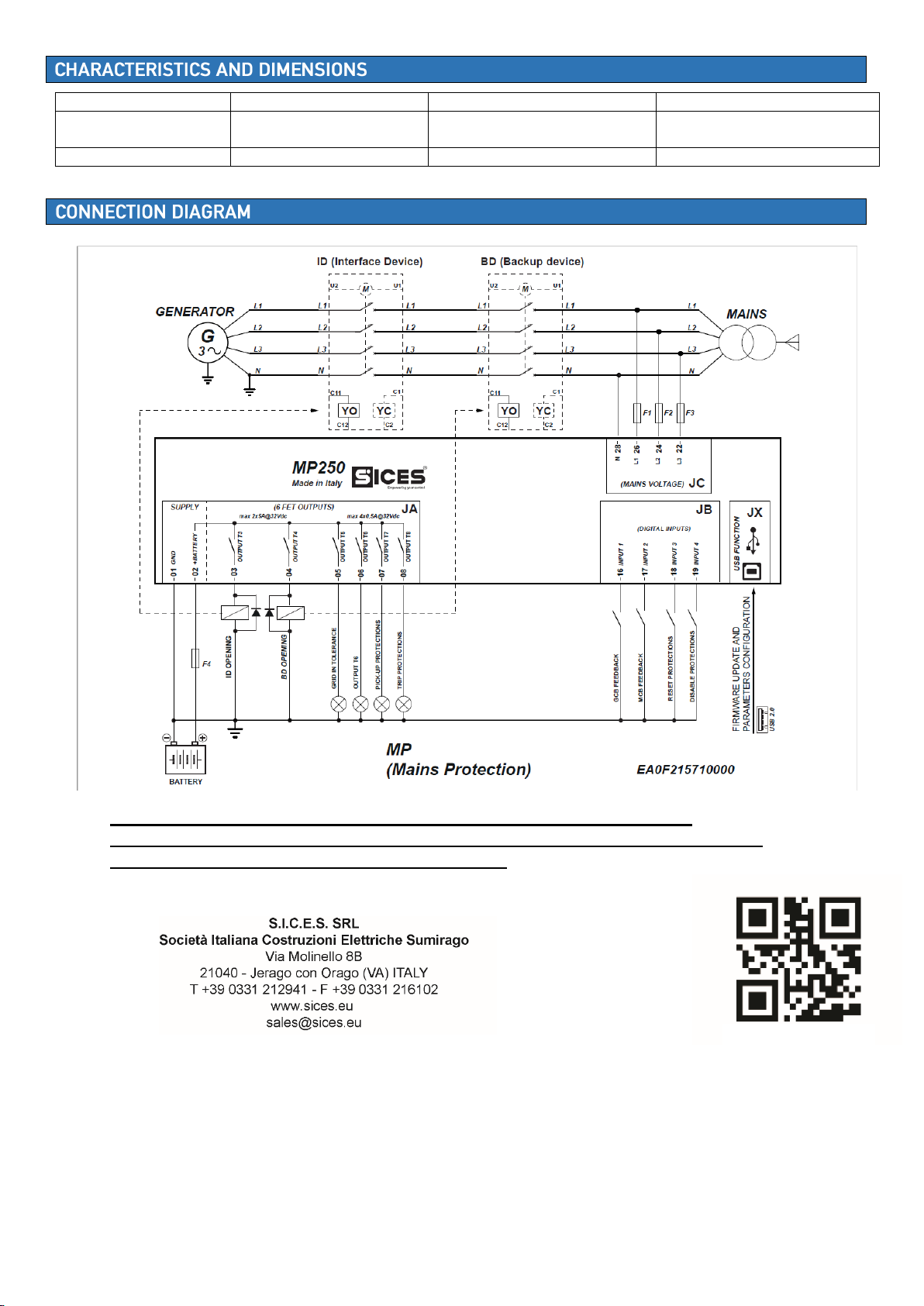
For further information on the device, related to the operation and
configuration, please refer to the technical documentation available in the
Download Area of the website www.sices.eu.
EAA0M067200EN


