SICK SCPS3300 User manual
MMMI
MMMOPERATING INSTRUCTIONS
O P E R A T I N G I N S T R U C T I O N S
SCPS3300
Gas Sampling System

28025339/V1-0/2020-03| SICKO P E R A T I N G I N S T R U C T I O N S | SCPS3300
Subject to change without notice
Described Product SCPS3300
Document ID 8025339
Manufacturer SICK AG AG
Erwin-Sick-Str. 1 · 79183 Waldkirch · Germany
www.sick.com
Production Location SICK AG AG
Gisela-Sick-Str. 1 · 79276 Reute · Germany
Legal Information This work is protected by copyright. Any rights derived from the copyright shall be reserved
for SICK AG. Reproduction of this document or parts of this document is only permissible
within the limits of the legal determination of Copyright Law. Any modification, reduction or
translation of this document is prohibited without the express written permission of SICK
AG.
The trademarks stated in this document are the property of their respective owner.
© SICK AG. All rights reserved
Original Document This document is an original document of SICK AG.

CONTENT
3
8025339/V1-0/2020-03| SICK O P E R A T I N G I N S T R U C T I O N S | SCPS3300
Subject to change without notice
1 About this Document ................................................................................ 7
1.2 Purpose of this Document ..............................................................................7
1.3 Target Group....................................................................................................7
1.4 Further Information.........................................................................................7
1.5 Additional Technical Documentation/Information ........................................8
1.6 Document Conventions...................................................................................8
2 Important Safety Instructions .................................................................. 9
2.1 Intended Use ...................................................................................................9
2.2 Supplemental Directives.................................................................................9
2.3 Requirements for the Qualification of Personnel .......................................... 9
2.4 Potential Hazards..........................................................................................10
2.5 Safety Devices...............................................................................................11
2.6 System Warranty ...........................................................................................11
2.7 RoHS-Directive ..............................................................................................11
2.8 Safety Conventions .......................................................................................12
2.9 Warning Signs on System Components .......................................................12
2.10 Mandatory Signs ...........................................................................................13
2.11 Safety Instructions ........................................................................................14
3 System Description .................................................................................17
3.1 SCP3000 - Gas Sampling System ................................................................18
3.1.1 Water Cooled Gas Sampling Probe ..............................................19
3.1.2 Shock Blow Device........................................................................20
3.1.3 Dust Filter......................................................................................21
3.1.4 Heated Sampling Line ..................................................................21
3.1.5 Rotation Device.............................................................................22
3.1.6 Retraction Device .........................................................................23
3.1.7 Sealing Box ...................................................................................24
3.1.8 Protection Tube.............................................................................24
3.1.9 On-site Control Panel with Signal Column ...................................25
3.1.10 Cooling Device ..............................................................................26
3.1.11 Control Cabinet .............................................................................27
3.1.12 Pneumatic/Compressed Air Service Unit ....................................27
3.1.13 MCS300P - Multicomponent Analysis System ............................28
3.1.14 MPR - Meeting Point Router (option) ...........................................29
4 Installation ................................................................................................31
4.1 Requirements for the System Location........................................................32
4.2 Probe Position ...............................................................................................32
4.3 Retraction Device..........................................................................................35
4.3.1 Installation Procedure ..................................................................36
4.4 Rotation Device and Sampling Probe ..........................................................41
4.4.1 Probe Axis Fine Tuning .................................................................42
4.4.2 Sealing Flange ..............................................................................42
Content

CONTENT
48025339/V1-0/2020-03| SICKO P E R A T I N G I N S T R U C T I O N S | SCPS3300
Subject to change without notice
4.5 Control Cabinets ........................................................................................... 43
4.5.1 Electrical Connections.................................................................. 44
4.5.2 Pneumatic Connections ............................................................... 44
4.6 MCS300P - Multicomponent Analysis System ............................................ 45
4.6.1 Bus Connections .......................................................................... 45
4.7 Cooling Unit................................................................................................... 46
4.7.1 Water to Water Cooling Unit......................................................... 46
4.7.2 Water to Air Cooling Unit .............................................................. 47
5 Commissioning ........................................................................................ 49
5.1 Operating Modes .......................................................................................... 49
5.1.1 Local Mode ................................................................................... 49
5.1.2 Automatic Mode ........................................................................... 49
5.2 Dust Filter Unit .............................................................................................. 50
5.3 Water to Water Cooling Unit......................................................................... 50
5.4 Water to Air Cooling Unit .............................................................................. 51
5.5 Setting and Monitoring Devices ................................................................... 51
5.6 Probe Position Check ................................................................................... 51
5.7 Automatic Mode............................................................................................ 52
5.8 MCS300P - Multicomponent Analysis System ............................................ 52
6 Operation .................................................................................................. 55
6.1 Control Cabinet ............................................................................................. 55
6.2 Local Panel.................................................................................................... 56
6.3 Operation Modes .......................................................................................... 57
6.3.1 Local Mode ................................................................................... 57
6.3.2 Automatic Mode ........................................................................... 57
6.4 Operating the Retraction Device .................................................................. 57
6.5 Emergency Retraction .................................................................................. 57
6.6 Back Flushing ............................................................................................... 58
6.7 Anti-Stick Routine ......................................................................................... 58
6.8 Dust Filter...................................................................................................... 58
6.9 MCS300P ...................................................................................................... 58
6.9.1 MCS300P Signals......................................................................... 59
6.9.2 MCS300P Modes ......................................................................... 60
7 Maintenance............................................................................................. 61
7.1 Leak Test....................................................................................................... 62
7.1.1 Leak Test 1 - Complete System Check with Negative Pressure . 62
7.1.2 Leak Test 2 - Complete System Check with Zero Gas ................ 64
7.1.3 Leak Test 3 - Probe and Filter Check with Positive Pressure ..... 66
8 Troubleshooting ....................................................................................... 69
8.1 Alarms ........................................................................................................... 69
8.2 Reset Alarms................................................................................................. 71
8.3 Action Table - SCPS3300 ............................................................................. 71


CONTENT
68025339/V1-0/2020-03| SICKO P E R A T I N G I N S T R U C T I O N S | SCPS3300
Subject to change without notice

7
8025339/V1-0/2020-03| SICK AG O P E R A T I N G I N S T R U C T I O N S | SCPS3300
Subject to change without notice
ABOUT THIS DOCUMENT 1
1 About this Document
1.1 Limitation of Liability
1.2 Purpose of this Document
This document describes the SCPS3300 - Gas Sampling System.
1.3 Target Group
This document is intended for qualified personnel which are authorized to work on the
SCPS3300.
1.4 Further Information
Special local conditions
Follow all local laws, technical rules, and company-internal operating directives applicable
at the respective installation site of the SCPS3300.
Preserving the documents
This document and the additional technical documentation and information must be:
●Available for reference.
●Passed on to new system operator or new employees.
Note
This document regarding the SCPS3300:
●contains information required during the life cycle of the System.
●is available to all those people who work with the System.
●read this document carefully and make sure that you understand the content fully
before working with the System.
Note
Applicable standards and regulations, the latest state of technological development and
many years of knowledge and experience have all been taken into account, when assem-
bling the data and information contained in this document.
The manufacturer accepts no liability for damage caused by:
●Failing to observe this document.
●Non-compliance of notices and regulations.
●Unauthorized mounting and installations.
●Arbitrary technical and other modifications.
●Use of unauthorized spare parts, consumables and accessories.
●Unauthorized modifications, adjustments and/or manipulation of software.
●Do not carry out regular maintenance work and its documentation.
With special variants, where optional extras have been ordered, or owing to the latest
technical changes, the actual scope of delivery may vary from the features and illustra-
tions shown here.
88025339/V1-0/2020-03| SICKO P E R A T I N G I N S T R U C T I O N S | SCPS3300
Subject to change without notice
1ABOUT THIS DOCUMENT
1.5 Additional Technical Documentation/Information
●Technical System-Documentation (EPLAN):
– SCP3000 - Gas Sampling System
>
Technical data
>
Wiring diagram
>
Terminal diagram
– MCS300P - Multicomponent Analysis System
>
Gas flow diagram
>
Wiring diagram
>
Terminal diagram
●Operating instructions of the following system components:
1.6 Document Conventions
Required tools
▸Instruction
Instruction result
All units of measurement in this document are originally metric units.
Subject to change without notice.
Images might differ from actual design.
Component Manufacturer
MCS300P - Multicomponent Analysis System SICK
SCP3000 - Gas Sampling System SICK
Refer to another document.

9
8025339/V1-0/2020-03| SICK AG O P E R A T I N G I N S T R U C T I O N S | SCPS3300
Subject to change without notice
IMPORTANT SAFETY INSTRUCTIONS 2
2 Important Safety Instructions
2.1 Intended Use
The SCPS3300 consist of the SCP3000 Gas Sampling System and the MCS300P - Multi-
component Analysis System.
The SCP3000 is used for sampling gas in high-temperature processes (up to 1,400 °C)
with high dust loads (up to 2,000 g/m3). The SCPS3300 is specially designed for sampling
gas at rotary kiln inlets in cement works.
The MCS300P measuring equipment serves for process monitoring of raw gas.
The measured medium is extracted at a sampling point and led through the cell of the
MCS300P (extractive measurement).
Intended use also includes compliance with this operating instructions, in particular the
safety instructions and the repair and maintenance conditions.
2.2 Supplemental Directives
▸Before working on the SCPS3300, read this document carefully and follow all safety
instructions and information.
▸Only qualified persons from the respective areas are permitted to work on the
SCPS3300.
▸Follow operating procedures.
▸Follow local regulations.
▸Observe local regulations for working with gas and electrical components.
▸Access to the SCPS3300 is restricted to authorized personnel only.
System damage/transport damage
▸Damage to individual components can lead to malfunctions of the entire system.
▸Do not ignore system components damaged during transport.
▸In the event of damage, contact SICK Service.
2.3 Requirements for the Qualification of Personnel
Only qualified personnel from the respective field are permitted to work on the system.
●Qualified personnel have the specialist training, skills, and experience, as well as knowl-
edge of the relevant regulations and standards, to be able to perform tasks delegated to
them and to detect and to avoid any potential dangers independently.
●Electricians have the specialist training, skills, and experience, as well as knowledge of
the relevant standards and provisions to be able to carry out work on electrical systems
and to detect and avoid any potential dangers independently.

10 8025339/V1-0/2020-03| SICKO P E R A T I N G I N S T R U C T I O N S | SCPS3300
Subject to change without notice
2IMPORTANT SAFETY INSTRUCTIONS
2.4 Potential Hazards
Toxic gases Toxic gases can lead to poisoning if the following is not observed:
▸Operate the system in adequately ventilated areas or rooms.
▸Use gas monitoring systems.
▸Only enter contaminated areas with PPE (breathing apparatus, gas detector).
▸Perform regular leakage tests.
Insertion/retraction Insertion/retraction during operation can lead to death or serious injury.
▸Note if yellow light on the on-site control panel flashes.
▸Leave dangerous area around the retraction device immediately.
Dangerous areas:
– in front of the sealing box at the kiln inlet chamber.
– close to the dust filter during probe rotation.
– on the retraction device drive.
Automatically retraction Automatically retracted probe due to power failure can lead to death or serious injury.
▸Leave the area around the retraction device immediately.
▸The pneumatic emergency drive triggers the retraction of the probe.
▸Due to power failure the yellow light at the signal column does not flash.
Unintentional insertion Unintentional insertion / retraction of the probe can lead to death or serious injury.
▸During all kind of works at the system secure the device against unintentional insertion
or retraction of the probe.
▸Lockout-Tagout the system.
▸Secure the working area against unauthorized interventions.
Explosive atmosphere Risk of explosion in an explosive atmosphere.
▸Do not operate the SCPS3300 in potentially explosive atmospheres.
Electric voltage Touching components that are live may result in death, burns or shock from electric shock.
Only qualified personnel may carry out electrical work on the system.
▸Before working on electrical components, observe the following safety rules:
▸ Disconnecting
▸ Secure against restarting
▸ Determine the absence of voltage
▸ Grounding and short-circuiting
▸ Cover or barrier adjacent live parts.
Hot surfaces Risk of injury from hot surfaces.
▸Do not touch hot surfaces.
▸Wear safety gloves and protective clothing.
Suspended loads Suspended loads can lead to injuries if the following is not observed:.
▸Never step under suspended loads.
▸Pay close attention when lifting loads.
▸Observe the lifting instructions to avoid injuries and accidents.
▸Use suitable undamaged lifting equipment.
▸Wear personal protective equipment (safety helmet, safety shoes).

11
8025339/V1-0/2020-03| SICK AG O P E R A T I N G I N S T R U C T I O N S | SCPS3300
Subject to change without notice
IMPORTANT SAFETY INSTRUCTIONS 2
2.5 Safety Devices
Enclosure:
▸Enclose the SCPS3300 if necessary.
▸Do not remove safety covers and barriers during operation.
2.6 System Warranty
Any warranty claim expires if:
▸Safety instructions and measures in this document are not observed.
▸Parts or components of the SCPS3300 are installed, assembled or modified without
authorization.
▸The SCPS3300 is changed or modified.
▸Software is changed, adapted and/or manipulated without authorization.
2.7 RoHS-Directive
This product is designed for applications in large industrial plants according to
Article 2 (4) e, RoHS 2011/65/EU and can therefore only be used in such systems.
The product is neither suitable nor approved for use outside of these systems.
SICK cannot assume any kind of warranty or liability for use outside of these systems..
12 8025339/V1-0/2020-03| SICKO P E R A T I N G I N S T R U C T I O N S | SCPS3300
Subject to change without notice
2IMPORTANT SAFETY INSTRUCTIONS
2.8 Safety Conventions
The warnings used in this manual have the following meanings:
2.9 Warning Signs on System Components
Do not remove or cover warning stickers. Damaged or missing stickers must be replaced.
DANGER
Indicates a hazardous situation with a high risk level, which if not avoided, will result
in death or serious injury.
WARNING
Indicates a hazardous situation with a middle risk level, which if not avoided, could
result in death or serious injury.
CAUTION
indicates a potentially dangerous situation with a low risk level, which if not avoided
may lead to minor or moderates injuries.
NOTICE
Indicates a situation which, if not avoided, may result in property damage to the system or
products in its vicinity.
Note
Indicates important information and useful hints..
Sign Significance
Warning of a danger point
Warning of dangerous electrical voltage
Warning of remotely started equipment
Warning of hot surfaces
Warning of suspended loads
Warning of corrosive substances
Warning of toxic substances

13
8025339/V1-0/2020-03| SICK AG O P E R A T I N G I N S T R U C T I O N S | SCPS3300
Subject to change without notice
IMPORTANT SAFETY INSTRUCTIONS 2
2.10 Mandatory Signs
Sign Significance
Harmful to health
Irritant
Environmental risk
Sign Significance
Read instructions manual
Wear safety gloves
Wear eye protection
Wear hard hat
Wear safety boots
Disconnect before maintenance or repair

14 8025339/V1-0/2020-03| SICKO P E R A T I N G I N S T R U C T I O N S | SCPS3300
Subject to change without notice
2IMPORTANT SAFETY INSTRUCTIONS
2.11 Safety Instructions
DANGER
Overhead loads - crush hazard.
Suspended loads could fall and cause death or serious injuries.
▸Never stand under suspended loads.
▸Exert extreme caution when hoisting the system.
▸Adhere to standard lifting procedures to prevent head injury and other accidents.
▸Wear personal protective equipment (hard hat, safety boots).
DANGER
Toxic gases.
Risk of intoxication by inhalation. Serious injuries or death.
▸Operate the system only in sufficient ventilated areas or rooms.
▸Use gas monitoring or gas warning detector.
▸In case of container contamination:
▸note the signal horn and flash light at the container.
▸wear appropriate respiratory protection before open the container door.
▸open the door to ventilate the container for at least 10 minutes.
▸Perform leakage test in appropriate time intervals.
DANGER
Hazardous voltage.
The system is supplied with mains voltage from the grid. Danger of electrocution -
contact will cause electric shock, burn or death.
▸Always exercise caution when handling cables and connectors.
▸Be aware of the risk of secondary accidents occurring if you are startled.
▸Before working on the system:
▸ Follow operational procedures such as Lockout-Tagout.
▸ Check that there is no residual voltage by measuring AC voltages.
DANGER
Insertion/retraction during operation
Serious injury or death.
▸Note if yellow light on the on-site control panel flashes.
▸Leave dangerous area around the retraction device immediately.
Dangerous areas:
– in front of the sealing box at the kiln inlet chamber.
– close to the dust filter during probe rotation.
– on the retraction device drive.
DANGER
Automatically retracted probe due to power failure
▸Leave the area around the retraction device immediately.
▸The pneumatic emergency drive triggers the retraction of the probe.
▸Due to power failure the yellow light at the signal column does not flash.

15
8025339/V1-0/2020-03| SICK AG O P E R A T I N G I N S T R U C T I O N S | SCPS3300
Subject to change without notice
IMPORTANT SAFETY INSTRUCTIONS 2
DANGER
Unintentional insertion / retraction of the probe
▸During all kind of works at the system secure the device against unintentional
insertion or retraction of the probe.
▸Lockout-Tagout the system.
▸Secure the working area against unauthorized interventions.
WARNING
Hot surfaces
Contact may cause burn and serious injuries.
▸Do not touch hot surfaces.
▸Use appropriate safety gloves.

16 8025339/V1-0/2020-03| SICKO P E R A T I N G I N S T R U C T I O N S | SCPS3300
Subject to change without notice
2IMPORTANT SAFETY INSTRUCTIONS

17
8025339/V1-0/2020-03| SICK AG O P E R A T I N G I N S T R U C T I O N S | SCPS3300
Subject to change without notice
SYSTEM DESCRIPTION 3
3 System Description
The SCPS3300 consist of the SCP3000 Gas Sampling System and the MCS300P - Multi-
component Analysis System.
The SCP3000 is used for sampling gas in high-temperature processes (up to 1,400 °C)
with high dust loads (up to 2,000 g/m3). The SCPS3300 is specially designed for sampling
gas at rotary kiln inlets in cement works.
The MCS300P measuring equipment serves for process monitoring of raw gas.
The measured medium is extracted at a sampling point and led through the cell of the
MCS300P (extractive measurement).
Fig. 1: System overview
Legend
1MCS300P - Multicomponent Analysis System
2MPR - Meeting Point Router (option)
3Control cabinet
4Pneumatic/compressed air service unit
5On-site control panel with signal column
6Air exhaust valve
7Cooling unit
8SCP3000 - Gas Sampling System
9Power cable
10 Instrument air hose
11 Hydraulic line
12 Heated sample gas line
18 8025339/V1-0/2020-03| SICK AGOP E R A T I N G I N S T R U C T I O N S | SCPS3300
Subject to change without notice
3SYSTEM DESCRIPTION
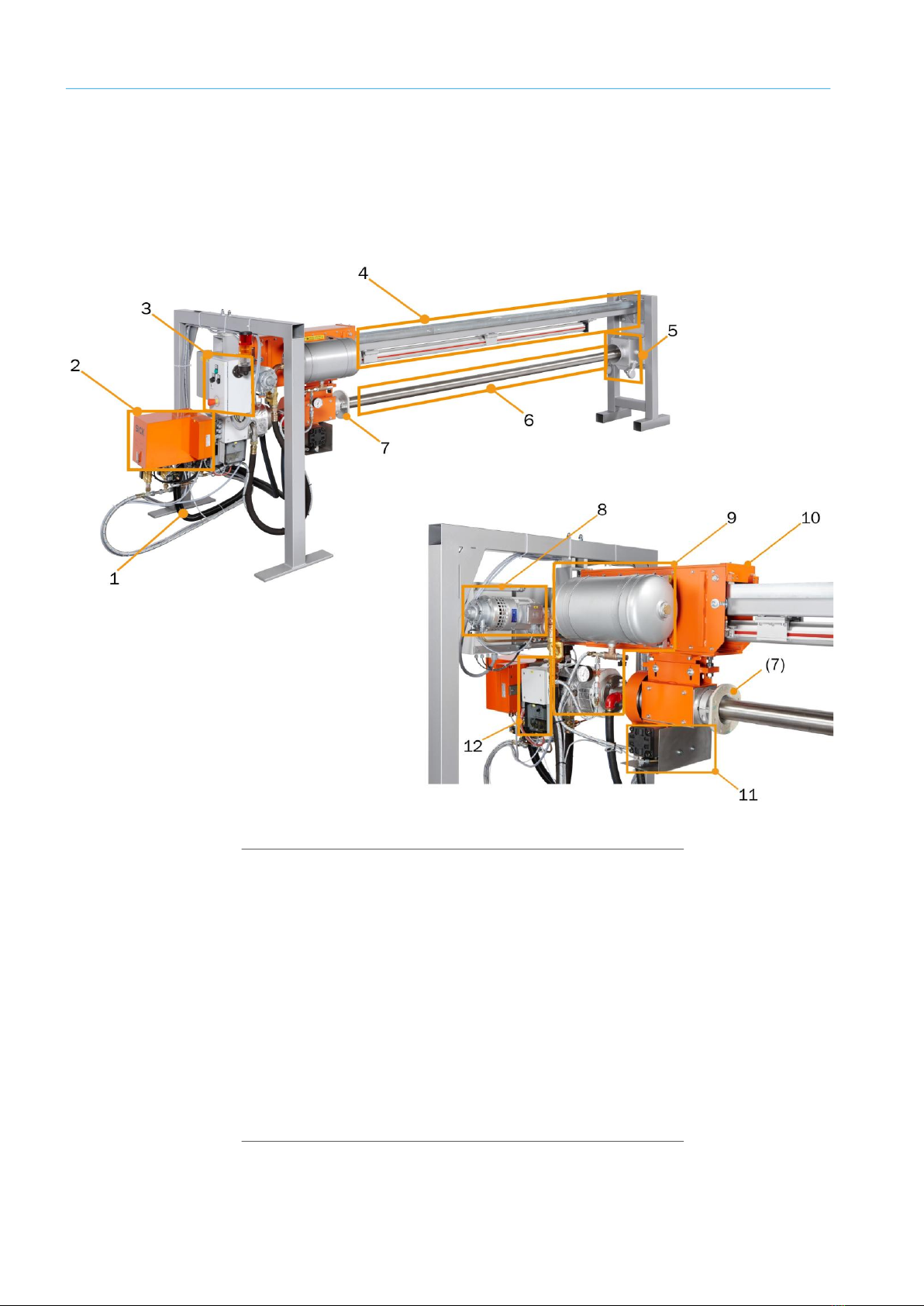
3.1 SCP3000 - Gas Sampling System
The SCP3000 Gas Sampling System is used for sampling gas in high-temperature pro-
cesses (up to 1,400 °C) with high dust loads (up to 2,000 g/m3).
The SCP3000 Gas Sampling System is specially designed for sampling gas at rotary kiln
inlets in cement works.
Fig. 2: SCP3000 components
Legend
1Heated sample gas line
2Dust filter unit
3On-site control panel with signal column
4Retraction device
5Sealing box
6Water cooled gas sampling probe
7Sealing flange
8Retraction device (electrical, pneumatic)
9Shock blow device
10 Carriage
11 Rotation unit
12 Temperature regulator / indicator

19
8025339/V1-0/2020-03| SICK AG O P E R A T I N G I N S T R U C T I O N S | SCPS3300
Subject to change without notice
SYSTEM DESCRIPTION 3
3.1.1 Water Cooled Gas Sampling Probe
Specifications ●Material: stainless steel (1.4841)
●Sampling aperture enables relatively dust-free gas flow.
●Continuous waster cooled.
●Controlled water cooling system. Gas temperature always stays above the acid dew point
of the gas to prevent deposits on and in the probe.
●Shock blow inlet to clean the gas sampling tube inside.
Fig. 3: Gas sampling probe, cross-section
Legend
1Sampling aperture
2Cooling water outlet
3Cooling waster inlet
4Shock blow inlet

20 8025339/V1-0/2020-03| SICK AGOP E R A T I N G I N S T R U C T I O N S | SCPS3300
Subject to change without notice
3SYSTEM DESCRIPTION
3.1.2 Shock Blow Device
Specifications ●Placed between SCP3000-F dust filter and probe.
●Directly mounted in line of the gas sampling tube of the probe.
●Pneumatic operated ball valve to cut off the sampling line to the dust filter.
●Heated sleeve on the inlet body with a maximum temperature of 160 °C.
●20 l tank filled with blast air.
●Valve to activate the air blast.
●Only proceeded when the probe is in measuring position inside the kiln.
●Activated at the beginning of the periodic back flushing routine, before the dust filter will
be cleaned.
●Check of the ball valve position by LEDs at the limit switches of the ball valve.
●In the event of loss of electrical power, the ball valve automatically closes the gas line to
the dust filter.
Fig. 4: Shock blow device
Legend
1Shock blow inlet body (without heated sleeve)
2Pneumatic operated ball valve
3Heated sleeve
4Limit switch ball valve open
5Limit switch ball valve closed
6Blast air tank
Table of contents
Other SICK Test Equipment manuals


