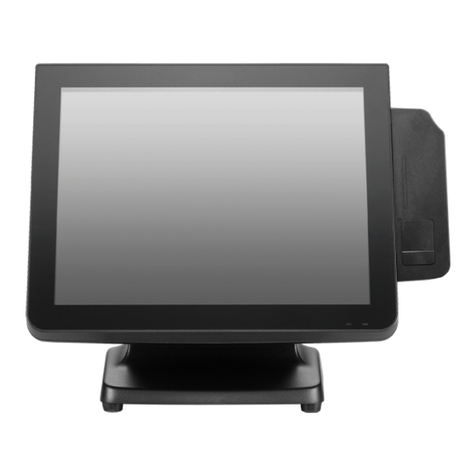
SICK SID Pro User manual

OPERATING INSTRUCTIONS
SID Pro
Sensor Visualization

Described product
SID Pro
Manufacturer
SICK AG
Erwin-Sick-Str. 1
79183 Waldkirch
Germany
Legal information
This work is protected by copyright. Any rights derived from the copyright shall be
reserved for SICK AG. Reproduction of this document or parts of this document is
only permissible within the limits of the legal determination of Copyright Law. Any modi‐
fication, abridgment or translation of this document is prohibited without the express
written permission of SICK AG.
The trademarks stated in this document are the property of their respective owner.
© SICK AG. All rights reserved.
Original document
This document is an original document of SICK AG.
2O P E R A T I N G I N S T R U C T I O N S | SID Pro 8027793/V1-0/2022-07-01 | SICK
Subject to change without notice

Contents
1 About this document........................................................................ 5
1.1 Limitation of liability................................................................................. 5
1.2 Purpose of this document........................................................................ 5
1.3 Further information................................................................................... 5
1.4 Symbols and document conventions...................................................... 5
2 Safety information............................................................................ 7
2.1 Basic safety instructions.......................................................................... 7
2.2 Important information.............................................................................. 8
2.3 Requirements for the qualification of personnel.................................... 8
2.4 Intended use............................................................................................. 9
2.5 Improper use............................................................................................. 9
2.6 RoHS Directive.......................................................................................... 9
2.7 Cybersecurity............................................................................................ 9
3 Product description........................................................................... 11
3.1 Scope of delivery....................................................................................... 11
3.2 Product characteristics............................................................................ 11
3.2.1 Integration................................................................................ 11
3.2.2 Hard drive partitions................................................................ 11
3.3 Optional accessories and services.......................................................... 12
4 Mounting............................................................................................. 13
4.1 Important information.............................................................................. 13
4.2 Mounting the panel PC............................................................................. 13
5 Electrical installation........................................................................ 14
5.1 Important information.............................................................................. 14
5.2 Connection overview................................................................................ 14
5.3 Relevant connections on the device........................................................ 15
5.4 Connecting the voltage supply................................................................. 15
5.4.1 Connecting the device to the mains supply........................... 16
5.4.2 Connecting the device to the fuse module in the control
cabinet...................................................................................... 16
5.5 Connecting the data cable....................................................................... 17
5.6 Connecting the customer network (optional).......................................... 18
6 Commissioning.................................................................................. 19
6.1 Important information.............................................................................. 19
6.2 Configuration............................................................................................. 19
6.3 Configuration software............................................................................. 19
6.3.1 Starting the SOPAS configuration software........................... 19
6.3.2 Establishing the remote desktop connection........................ 20
7 Operation............................................................................................ 22
CONTENTS
8027793/V1-0/2022-07-01 | SICK O P E R A T I N G I N S T R U C T I O N S | SID Pro 3
Subject to change without notice

7.1 Switching the device on/off..................................................................... 22
8 Maintenance...................................................................................... 23
8.1 Important information.............................................................................. 23
8.2 Cleaning the cooling fins of the device................................................... 23
9 Decommissioning............................................................................. 25
10 Technical data.................................................................................... 26
10.1 Features.................................................................................................... 26
10.2 Interfaces.................................................................................................. 26
10.3 Mechanics and electronics...................................................................... 26
10.4 Ambient data............................................................................................. 27
10.5 Dimensional drawings.............................................................................. 27
CONTENTS
4O P E R A T I N G I N S T R U C T I O N S | SID Pro 8027793/V1-0/2022-07-01 | SICK
Subject to change without notice

1 About this document
1.1 Limitation of liability
Applicable standards and regulations, the latest technological developments, and our
many years of knowledge and experience have all been taken into account when
assembling the data and information contained in this document.
The manufacturer accepts no liability for damage caused by:
•Failure to observe this document.
•Non-compliance with notes and regulations.
•Unauthorized mounting and installation.
•Unauthorized technical and other changes.
•Use of unauthorized spare parts, wear and tear parts, and accessories.
•Unauthorized changes, adjustments, and/or manipulations of software.
The actual scope of delivery may differ from the features and illustrations shown here
where special variants are involved, if optional extras have been ordered, or as a result
of the latest technical changes.
1.2 Purpose of this document
This document describes the following product:
SID Pro
bThe document must be made available to all persons who work with the product.
bRead through the document carefully and ensure that you have full understood the
content before working with the product.
1.3 Further information
Other documents relevant for the product
Document Manufacturer
Operating instructions GOT315W Axiomtek
GOT315W data sheet Axiomtek
Mounting instructions for the monitor arm item
1.4 Symbols and document conventions
Safety icons on the device and on the device components, as well as safety notes and
safety labels, correspond to the current guidelines and standards.
The safety conventions for signal words used in this document conform to ANSI Z535.
DANGER
Indicates a situation presenting imminent danger, which will lead to death or serious
injuries if not prevented.
WARNING
Indicates a situation presenting possible danger, which may lead to death or serious
injuries if not prevented.
ABOUT THIS DOCUMENT 1
8027793/V1-0/2022-07-01 | SICK O P E R A T I N G I N S T R U C T I O N S | SID Pro 5
Subject to change without notice

CAUTION
Indicates a situation presenting possible danger, which may lead to moderate or minor
injuries if not prevented.
NOTICE
Indicates a situation presenting possible danger, which may lead to property damage if
not prevented.
NOTE
Indicates useful tips and recommendations.
Instructions to action
bThe arrow denotes instructions to action.
1. The sequence of instructions is numbered.
2. Follow the order in which the numbered instructions are given.
✓The tick denotes the results of an action.
1 ABOUT THIS DOCUMENT
6O P E R A T I N G I N S T R U C T I O N S | SID Pro 8027793/V1-0/2022-07-01 | SICK
Subject to change without notice

2 Safety information
2.1 Basic safety instructions
DANGER
Danger of electric shock due to electrical voltage. Contact will result in death, burns or
shock.
bElectrical work may only be performed on the system by qualified specialist per‐
sonnel.
bInterrupt the voltage supply.
bCheck residual voltage on the system components.
bUse extra caution.
bAlways connect equipotential bonding (earthing).
bEnsure that the ground potential is the same at all grounding points.
bDo not disconnect or remove the protective conductor.
WARNING
Risk of injury and damage caused by electrical current
Due to equipotential bonding currents, incorrect earthing can lead to the following
dangers and faults: Voltage is applied to the metal housing, cable fires due to cable
shields heating up, the product and other devices become damaged.
bGenerate the same ground potential at all grounding points.
bGround the equipotential bonding via the functional ground connection with a low
impedance.
WARNING
The surface of the device can become hot during operation.
bBefore commencing disassembly, switch off the device and allow it to cool down
as necessary.
CAUTION
The cooling fins must not be covered or restricted in their functionality.
NOTICE
bOnly qualified persons from the relevant departments are permitted to work on the
device.
bFollow operating processes.
bFollow local regulations.
bOnly authorized persons are permitted access to the system.
bGenerate the same ground potential at all grounding points.
Special local conditions:
bThe local laws, regulations, technical rules and internal company operating instruc‐
tions at the usage site must be observed.
Storage of documents:
This document and further technical documentation/information
bMust be kept available for reference.
bMust be handed on to new operating entities/new specialist personnel.
SAFETY INFORMATION 2
8027793/V1-0/2022-07-01 | SICK O P E R A T I N G I N S T R U C T I O N S | SID Pro 7
Subject to change without notice

2.2 Important information
NOTICE
General disclaimer
SICK AG shall not be liable for any damage arising out of any incompatibility between
the software provided to you, OEM software, any relevant software patches and the
software previously provided to you (except the factory default), and your other software
and/or hardware.
NOTICE
Possible incompatibility due to customer software programs
All software components required for the intended use of the device have been pre-
installed on the device.
SICK AG shall not be liable for any damage arising out of any incompatibility between
the factory pre-installed software components and software installed by the customer.
Do not change the factory settings.
NOTICE
Possible incompatibility due to extending the hardware components
All hardware components required for the intended use of the device have been pre-
installed in the device.
Do not make any hardware modifications.
Do not extend the hardware components installed in the device.
NOTICE
Own responsibility for data backup in the event of repairs
After repair by the SICK Service department, the device will be returned to the customer
in the delivery state. Customer-specific data and images will be deleted.
SICK will not back up the customer-specific data and images.
Before sending the device to SICK, back up the customer-specific images and data.
After backing up the customer-specific images and data, delete them from the device.
NOTICE
No redundant data storage
The device is not a RAID system. There is no redundant data storage.
Damage to the hard drive can result in loss of data.
Regularly back up the data stored on the device to an external storage medium.
2.3 Requirements for the qualification of personnel
•Qualified persons have the specialist training, skills, experience and knowledge
of the relevant regulations and standards needed to be able to perform work
assigned to them and to identify and avoid any potential dangers independently.
•Electricians have the professional training, skills, experience and knowledge of the
relevant standards and provisions needed to work on electrical systems and to
detect and avoid any potential dangers independently.
2 SAFETY INFORMATION
8O P E R A T I N G I N S T R U C T I O N S | SID Pro 8027793/V1-0/2022-07-01 | SICK
Subject to change without notice

2.4 Intended use
WARNING
The product must only be used for the intended use. Non-intended use can pose a
hazard to people and cause damage to the device.
The device is an industrial PC that operates in conjunction with SICK sensors. The
device is integrated into a SICK system and receives the data from the individual
system components.
NOTE
Intended use also includes observance of these operating instructions, in particular the
safety notes as well as the repair and maintenance requirements.
2.5 Improper use
Any use outside of the stated areas, in particular use outside of the technical specifica‐
tions and the requirements for intended use, will be deemed to be incorrect use.
•The device does not constitute a safety component in accordance with the respec‐
tive applicable safety standards for machines.
•The device must not be used in explosion-hazardous or corrosive areas or under
extreme ambient conditions.
•Any use of accessories not specifically approved by SICK AG is at your own risk.
WARNING
Danger due to improper use!
Any improper use can result in dangerous situations.
Therefore, observe the following information:
■Product should be used only in accordance with its intended use.
■All information in the documentation must be strictly observed.
■Shut down the product immediately in case of damage.
2.6 RoHS Directive
This product has been designed for specific applications in large industrial plants
according to
Article 2 (4) e, RoHS 2011/65/EU, and must therefore only be used in such plants.
The product is neither suitable nor approved for use outside of these systems. SICK
therefore cannot provide any warranty or accept any liability whatsoever for such use.
2.7 Cybersecurity
Overview
To protect against cybersecurity threats, it is necessary to continuously monitor and
maintain a comprehensive cybersecurity concept. A suitable concept consists of organi‐
zational, technical, procedural, electronic, and physical levels of defense and considers
suitable measures for different types of risks. The measures implemented in this
product can only support protection against cybersecurity threats if the product is used
as part of such a concept.
SAFETY INFORMATION 2
8027793/V1-0/2022-07-01 | SICK O P E R A T I N G I N S T R U C T I O N S | SID Pro 9
Subject to change without notice

You will find further information at www.sick.com/psirt, e.g.:
•General information on cybersecurity
•Contact option for reporting vulnerabilities
•Information on known vulnerabilities (security advisories)
2 SAFETY INFORMATION
10 O P E R A T I N G I N S T R U C T I O N S | SID Pro 8027793/V1-0/2022-07-01 | SICK
Subject to change without notice

3 Product description
3.1 Scope of delivery
NOTICE
bAfter delivery, inspect the product for transport damage and report any such
damage immediately.
bCheck that the delivery includes all components listed on the delivery note.
3.2 Product characteristics
Overview
•Powerful panel PC with pre-installed Windows operating system
3.2.1 Integration
Overview
Figure 1: Integration of the panel PC into the SICK system
1Panel PC
2SICK system
3Transmission of measurement and read results, image data and status information via
Ethernet
4Data output
5Client computer
6Customer network (connection optional)
3.2.2 Hard drive partitions
The hard drive of the device is divided into three partitions.
Partition Contents
C:\ Partition with the pre-installed Windows 10 IoT operating system
D:\ Partition with pre-installed software components:
•SOPAS configuration software
•Optional: Package Analytics analysis platform
PRODUCT DESCRIPTION 3
8027793/V1-0/2022-07-01 | SICK O P E R A T I N G I N S T R U C T I O N S | SID Pro 11
Subject to change without notice

Partition Contents
E:\ Partition for saving the accepted measurement and read results, cam‐
era images and status information in a directory structure.
The directory structure must be configured accordingly.
3.3 Optional accessories and services
Separately available accessories
•Monitor bracket and fastening materials for mounting
•Power supply unit with bare ended power cord
Patch management
•Patch management available on request
•Regular installation of security updates for the pre-installed operating system.
3 PRODUCT DESCRIPTION
12 O P E R A T I N G I N S T R U C T I O N S | SID Pro 8027793/V1-0/2022-07-01 | SICK
Subject to change without notice

4 Mounting
4.1 Important information
NOTICE
All transport, assembly, mounting, and electrical installation work must only be carried
out by qualified persons.
•Qualified persons have the specialist training, skills, experience and knowledge
of the relevant regulations and standards needed to be able to perform work
assigned to them and to identify and avoid any potential dangers independently.
•Electricians have the professional training, skills, experience and knowledge of the
relevant standards and provisions needed to work on electrical systems and to
detect and avoid any potential dangers independently.
4.2 Mounting the panel PC
Overview
The following mounting variants exist:
•Front-loading mounting (in the control cabinet)
•VESA mounting (procedure is described below)
°VESA mounting system with telescopic and swivel function is available as an
accessory.
°The rear of the panel PC has a mounting hole pattern that is intended for use
with the VESA bracket.
Approach
1. Insert the two sliding nuts into the slot on the aluminum profile.
2. Attach the mounting arm to the frame using the two screw holes in the mounting
profile.
3. Mount the VESA bracket on the rear of the panel PC using the four fixing screws.
4. Place the VESA bracket on the mounting arm and screw them together.
MOUNTING 4
8027793/V1-0/2022-07-01 | SICK O P E R A T I N G I N S T R U C T I O N S | SID Pro 13
Subject to change without notice

5 Electrical installation
5.1 Important information
DANGER DURCH ELEKTRISCHE SPANNUNG
Supply voltage: 24VDC.
Touching live devices, which may still be energized, can lead to death, burns or electri‐
cal shock.
bElectrical work may only be performed on the system by qualified specialist per‐
sonnel.
bAlways connect equipotential bonding (earthing).
bDo not disconnect or remove the protective conductor.
bThe voltage supply must be disconnected when attaching or detaching electrical
connections.
bBefore working on electrical components, observe the five safety rules:
°Disconnect.
°Secure against being switched back on.
°Ensure that there is no voltage.
°Ground and short-circuit.
°Cover or enclose live parts in the vicinity.
NOTICE
All electrical work may only be performed by qualified persons.
•Qualified persons have the specialist training, skills, experience and knowledge
of the relevant regulations and standards needed to be able to perform work
assigned to them and to identify and avoid any potential dangers independently.
•Electricians have the professional training, skills, experience and knowledge of the
relevant standards and provisions needed to work on electrical systems and to
detect and avoid any potential dangers independently.
5.2 Connection overview
Figure 2: Connection overview
1Panel PC
5 ELECTRICAL INSTALLATION
14 O P E R A T I N G I N S T R U C T I O N S | SID Pro 8027793/V1-0/2022-07-01 | SICK
Subject to change without notice

2SICK system
3Data cable (Ethernet)
4Data output
5Client computer
6Customer interface (connection optional)
5.3 Relevant connections on the device
Overview
The following connections are relevant for integrating the device into the SICK system.
Figure 3: Relevant connections on the rear of the panel PC
1Voltage supply
2USB connections
3Ethernet ports: Connection
•to the customer interface for accessing the panel PC via the customer network
•of the data cable for integrating the panel PC into the SICK system
•of the configuration PC
4COM1 for RS232/422/485
NOTE
A description of all the connections on the device can be found in the manufacturer’s
operating instructions.
5.4 Connecting the voltage supply
The following connection variants are possible:
•Connecting the device to the mains supply
This variant is suitable when expanding a SICK system with an industrial PC.
NOTE The socket must be provided by the customer at the installation loca‐
tion.
•Connecting the device to the fuse module in the control cabinet
This variant is particularly suitable for use when setting up a new SICK system and
it is planned to integrate an industrial PC.
ELECTRICAL INSTALLATION 5
8027793/V1-0/2022-07-01 | SICK O P E R A T I N G I N S T R U C T I O N S | SID Pro 15
Subject to change without notice

5.4.1 Connecting the device to the mains supply
Important information
DANGER FROM ELECTRICAL VOLTAGE
The system is supplied with line voltage. Risk of electrical shock. Contact will result in
death, burns or shock.
bElectrical work may only be performed on the system by qualified specialist per‐
sonnel.
bInterrupt the voltage supply.
bCheck residual voltage on the system components.
bUse extra caution.
bAlways connect equipotential bonding (earthing).
bDo not disconnect or remove the protective conductor.
bThe voltage supply must be disconnected when attaching or detaching electrical
connections.
Prerequisites
A suitable power supply unit with two connecting cables for connecting the device to
the mains supply is available as an accessory.
Approach
1. Connect the wires of the cable extending from the power supply unit to the supply
connector.
2. Connect the supply connector to the 9-32V DC IN connection.
3. Screw together the plug connection.
4. Establish a connection to the local mains supply via the power cord.
5.4.2 Connecting the device to the fuse module in the control cabinet
Overview
Figure 4: Connection to the fuse module in the control cabinet
12-wire connecting cable open at both ends
2Terminals in the control cabinet (24VDC)
3Power supply unit
NOTICE
The power supply unit installed in the control cabinet must provide at least 160W of
power.
5 ELECTRICAL INSTALLATION
16 O P E R A T I N G I N S T R U C T I O N S | SID Pro 8027793/V1-0/2022-07-01 | SICK
Subject to change without notice

Important information
DANGER
Do not use the service socket of the control cabinet
bThe socket provided in the control cabinet is not factory equipped with a residual
current device (RCD).
bDo not use the socket to connect the device!
bThe socket can only be used by qualified electricians for service purposes, e.g.,
to connect a laptop. If necessary, insert a mobile plug-in FI circuit-breaker in the
socket according to the safety concept provided by the customer.
Approach
1. Connect the wires of the cable to the supply connector
2. Connect the supply connector to the 9-32V DC IN connection.
3. Screw together the plug connection.
4. Lead cable through the PG connector of the control cabinet and fasten cable entry.
5. Remove approx. 10mm of the insulation from both wires.
6. Twist the wire ends.
NOTICE
Do not use ferrules!
Do not solder the wire ends!
7. Lay wires on the fuse module of the control cabinet in accordance with the circuit
diagram.
5.5 Connecting the data cable
Overview
The device is connected to the SICK system via an Ethernet cable with RJ45 plug
connectors at both ends. The device is connected to the SICK system at a free port on
the controller or the Ethernet switch.
The device can be connected via one of the available ports.
Information about the Ethernet ports on the device
•Total number of Ethernet ports: 2
•Thereof freely configurable ports (DHCP interfaces): 1
Ports IP address
1 (LAN1) DHCP
2 (LAN2) 192.168.0.102*
*If this IP address is changed, it will no longer be possible to access the device via the remote desktop
connection.
NOTE
Which port to use on the device depends on the IP address range the other devices
of the SICK system are in, and over which interface the configuration PC is to be
connected.
ELECTRICAL INSTALLATION 5
8027793/V1-0/2022-07-01 | SICK O P E R A T I N G I N S T R U C T I O N S | SID Pro 17
Subject to change without notice

5.6 Connecting the customer network (optional)
Prerequisites
•The customer interface must be connected via the DHCP port LAN1.
•The port used must first be configured to be in the address range of the customer
network and be enabled in the firewall of the customer network.
Approach
bConfigure the Ethernet port on the device.
bTo do so, assign an IP address from the address range of the customer network.
bPlug the Ethernet cable into the DHCP port.
bConnect the cable to the customer network.
5 ELECTRICAL INSTALLATION
18 O P E R A T I N G I N S T R U C T I O N S | SID Pro 8027793/V1-0/2022-07-01 | SICK
Subject to change without notice

6 Commissioning
6.1 Important information
NOTICE
Commissioning may only be performed by qualified persons.
•Qualified persons have the specialist training, skills, experience and knowledge
of the relevant regulations and standards needed to be able to perform work
assigned to them and to identify and avoid any potential dangers independently.
•Electricians have the professional training, skills, experience and knowledge of the
relevant standards and provisions needed to work on electrical systems and to
detect and avoid any potential dangers independently.
6.2 Configuration
Configuration is performed via a separate configuration computer or directly via the
touchscreen on the panel PC.
Depending on how the data cable is connected, the configuration computer is con‐
nected directly to the device or via the controller or Ethernet switch.
6.3 Configuration software
The following software components are pre-installed on the device:
•SOPAS configuration software
6.3.1 Starting the SOPAS configuration software
Approach
bStart SOPAS either on the configuration PC, or on the device via a remote desktop
connection depending on the connection scenario.
Figure 5: Open SOPAS via the remote desktop connection
COMMISSIONING 6
8027793/V1-0/2022-07-01 | SICK O P E R A T I N G I N S T R U C T I O N S | SID Pro 19
Subject to change without notice

Figure 6: Open SOPAS on the configuration computer
bStart the program via the desktop icon or the Windows Start menu.
✓A new project is automatically created in SOPASET. One or more devices are
combined and edited in a single project.
6.3.2 Establishing the remote desktop connection
Overview
A default remote desktop user has been created on the device and configured for
establishing a remote desktop connection.
Prerequisites
•Make sure that the device has been switched on and is running properly.
•The device must not be in energy saving or sleep mode!
Approach
Starting the remote desktop connection
1. Open the start menu of the operating system.
2. Under Programs, select the Remote Desktop Connection program.
3. Click Show Options.
4. In the Computer field, enter the IP address of the predefined Ethernet port (LAN2):
192.168.0.102
NOTE
The network connection is established via the IP address of the predefined Ether‐
net port, regardless of how the configuration PC is connected.
5. In the User name field, enter the remote desktop user already set up on the
device: “Engineering”.
The password is entered later when establishing the connection.
Starting the remote desktop connection
1. Click on Connect.
✓The remote desktop connection is established.
2. Log in to the device as the remote desktop user Engineering .
The password can be obtained from the local technical contact person.
NOTE
In addition to the Engineering user, an Operator user has also been pre-installed
on the device.
3. Click OK.
✓The security prompt regarding the identity of the remote computer is displayed.
6 COMMISSIONING
20 O P E R A T I N G I N S T R U C T I O N S | SID Pro 8027793/V1-0/2022-07-01 | SICK
Subject to change without notice
Table of contents
