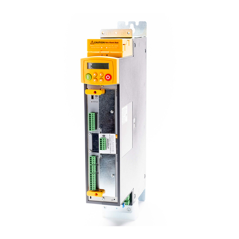
SIEB & MEYER SD2S 0362X49xy Guide

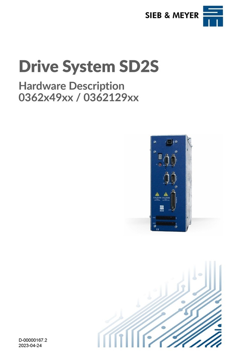
Drive System SD2S
Hardware Descripon
0362X49xy / 0362129xy
P-TD-0000452.7
2020-02-14
SIEB & MEYER W

Copyright
Translation of the original instructions, Copyright © 2020 SIEB & MEYER AG
All rights reserved.
This manual or extracts thereof may only be copied with the explicit authorization of
SIEB & MEYER AG.
Trademarks
All product, font and company names mentioned in this manual may be trademarks or registered
trademarks of their respective companies.
SIEB & MEYER worldwide
For questions regarding our products and technical problems please contact us.
SIEB & MEYER AG
Auf dem Schmaarkamp 21
21339 Lueneburg
Germany
Phone: +49 4131 203 0
Fax: +49 4131 203 2000
http://www.sieb-meyer.de
SIEB & MEYER Shenzhen Trading Co. Ltd.
Room A208, 2/F,
Internet Innovation and Creation services base
Building (2),
No.126, Wanxia road, Shekou, Nanshan district,
Shenzhen City, 518067
China
Phone: +86 755 2681 1417 / +86 755 2681 2487
Fax: +86 755 2681 2967
http://www.sieb-meyer.cn
SIEB & MEYER Asia Co. Ltd.
4 Fl, No. 532, Sec. 1
Min-Sheng N. Road
Kwei-Shan Hsiang
333 Tao-Yuan Hsien
Taiwan
Phone: +886 3 311 5560
Fax: +886 3 322 1224
http://www.sieb-meyer.com
W
2 Drive System SD2S - Hardware Description 0362X49xy / 0362129xy

About this Manual 1
General Information 2
Safety Instructions 3
Unit Assembly Complying EMC 4
Drive Amplifier SD2S 5
Device Description 6
Connector Pin Assignment 7
Connection Examples 8
Setup 9
Status Display and Error Messages 10
General Information Regarding the Wiring 11
Safety Circuit / Restart Lock (STO) 12
Appendix 13
Index 14
WChapter Overview
Drive System SD2S - Hardware Description 0362X49xy / 0362129xy 3

Chapter Overview W
4 Drive System SD2S - Hardware Description 0362X49xy / 0362129xy

1 About this Manual ............................................................. 9
1.1 Illustration of Warnings ............................................................................... 9
1.2 Illustration of General Notices ................................................................... 10
1.3 Technical Symbols .................................................................................... 10
1.4 Abbreviations ............................................................................................ 10
2 General Information ........................................................ 13
2.1 Approval for the Markets in USA and Canada .......................................... 13
2.2 NRTL Requirements ................................................................................. 14
3 Safety Instructions ........................................................... 17
3.1 Standards and Regulations ....................................................................... 17
3.2 Working on the Device .............................................................................. 17
3.3 Appropriate Use ........................................................................................ 18
3.4 Reasonably Foreseeable Misuse .............................................................. 19
3.5 Transport and Storage .............................................................................. 19
3.6 Installation ................................................................................................. 20
3.7 Electrical Connection ................................................................................ 21
3.8 Operation .................................................................................................. 22
3.9 Maintenance ............................................................................................. 23
3.10 Disposal .................................................................................................... 23
3.11 Legal Warranty .......................................................................................... 24
4 Unit Assembly Complying EMC ...................................... 25
4.1 Emission of Line and Field Interferences According to Category C3 ........ 25
5 Drive Amplifier SD2S ...................................................... 27
5.1 Block Diagram ........................................................................................... 27
5.2 Type Plate ................................................................................................. 28
5.3 Device name ............................................................................................. 29
6 Device Description .......................................................... 31
6.1 Dimensions ............................................................................................... 32
6.2 Wall Mounting ........................................................................................... 32
6.3 Technical Data .......................................................................................... 33
6.4 Connectors ................................................................................................ 35
7 Connector Pin Assignment .............................................. 37
7.1 Operation of the Terminal Connectors ...................................................... 37
7.1.1 Click & Lock System (STCL Connectors) ............................................................. 37
7.1.2 Push-in Technology .............................................................................................. 37
7.2 ID switch ................................................................................................... 37
7.3 X6 – Encoder 0 ......................................................................................... 38
7.4 X7 – Encoder 1 / Encoder Emulation ........................................................ 38
7.5 X14 – USB ................................................................................................ 39
7.6 X10 – Safety (STO) ................................................................................... 39
7.7 X15 – Digital Outputs ................................................................................ 40
7.7.1 Digital Outputs – SERVO / VECTOR .................................................................... 40
WContent
Drive System SD2S - Hardware Description 0362X49xy / 0362129xy 5

7.7.2 Digital Outputs– VF ............................................................................................... 41
7.8 X16 – Digital Inputs ................................................................................... 42
7.8.1 Digital Inputs – SERVO / VECTOR ....................................................................... 42
7.8.2 Digital Inputs – VF ................................................................................................. 44
7.9 X17 – Motor Feedback .............................................................................. 45
7.10 X18 – Analog Interface .............................................................................. 46
7.11 X19 – COM1 / Operating Terminal ............................................................ 48
7.12 X26/ X27 – SERVOLINK 4 ........................................................................ 48
7.12.1 Preparation of Optical Fiber Cables with Connector ............................................. 49
7.13 X44 – Power Supply .................................................................................. 50
7.14 X45 – Motor Connection ........................................................................... 51
7.15 X63 – External Ballast Resistor ................................................................. 52
7.16 X64/X65 – EtherCAT ................................................................................. 52
8 Connection Examples ..................................................... 55
8.1 X6, X7 – Incremental Encoder with TTL Signals ....................................... 55
8.2 X7 – Encoder Emulation ........................................................................... 56
8.3 safety circuit (STO) ................................................................................... 56
8.3.1 Wiring with OSSD ................................................................................................. 57
8.3.2 Wiring without OSSD ............................................................................................ 57
8.4 X15 – Digital Outputs / NAMUR Sensor / PULSE IN / Digital Field Plate /
GMR .......................................................................................................... 57
8.4.1 Digital Outputs ....................................................................................................... 57
8.4.2 NAMUR sensor ..................................................................................................... 58
8.4.3 PULSE IN 24 V ..................................................................................................... 58
8.4.4 Digital Field Plate / GMR ....................................................................................... 59
8.4.5 PULSE (Speed Pulses) ......................................................................................... 60
8.5 X16/17 – Digital Inputs .............................................................................. 60
8.6 X17 – Motor Feedback .............................................................................. 61
8.6.1 Resolver ................................................................................................................ 61
8.6.2 Incremental Encoder with Sine Signals (1 Vpp) ..................................................... 62
8.6.3 Linear Hall Encoder (1 Vpp) ................................................................................... 63
8.6.4 EnDat 2.1 with Sine Signals (1 Vpp) ...................................................................... 64
8.6.5 Hiperface with Sine Signals .................................................................................. 65
8.6.6 Hall Sensor 12 V ................................................................................................... 66
8.6.7 Hall Sensor 5.3 V .................................................................................................. 67
8.6.8 Field Plate ............................................................................................................. 68
8.6.9 Incremental Encoder with TTL Signals (5.3 V) ...................................................... 69
8.6.10 Incremental Encoder 12 V ..................................................................................... 70
8.6.11 PULSE IN 5 V ....................................................................................................... 71
8.6.12 Temperature Sensor of the Motor ......................................................................... 71
8.7 X18 – Analog Inputs/Outputs .................................................................... 72
8.7.1 Analog Outputs ..................................................................................................... 72
8.7.2 Analog Inputs ........................................................................................................ 73
8.8 X19 – Bus Connection .............................................................................. 73
8.8.1 COM1 – RS232 ..................................................................................................... 73
8.8.2 CAN Bus ............................................................................................................... 74
8.9 X26/X27 – SERVOLINK ............................................................................ 75
8.10 X44 – Power Supply .................................................................................. 75
8.11 X45 – Motor Phases .................................................................................. 76
Content W
6 Drive System SD2S - Hardware Description 0362X49xy / 0362129xy

8.12 Shielding of the Motor Cable ..................................................................... 77
8.13 X63 – External Ballast Resistor ................................................................. 77
8.14 X64/X65 – EtherCAT ................................................................................. 78
8.15 Housing Ground ........................................................................................ 78
9 Setup ............................................................................... 79
9.1 SD2S Connection and Switch-on .............................................................. 79
9.2 Parameter Setting and Initial Operation .................................................... 79
10 Status Display and Error Messages ................................ 81
10.1 LED Status Display: EtherCAT Connection .............................................. 81
10.2 7-segment display ..................................................................................... 82
10.2.1 List of the Operating States ................................................................................... 82
10.2.2 List of Drive Error Messages ................................................................................. 83
10.2.3 List of Warning Messages ..................................................................................... 87
10.2.4 Message of the Quick Stop Functions .................................................................. 88
11 General Information Regarding the Wiring ...................... 89
11.1 Mains Connection ..................................................................................... 89
11.1.1 Mains Chokes ....................................................................................................... 89
11.2 Cable Requirements ................................................................................. 89
11.2.1 Motor Cable ........................................................................................................... 92
11.2.2 Communication Cable ........................................................................................... 93
11.2.3 Cables for the Rotor Position Detection ................................................................ 93
11.2.4 Cables for the External Ballast Resistor ................................................................ 94
12 Safety Circuit / Restart Lock (STO) ................................. 95
12.1 Functional Description of the Restart Lock ............................................... 96
12.2 Wiring Example ......................................................................................... 97
12.3 Requirements and Standards ................................................................... 98
12.4 Restart Lock Procedure ............................................................................ 99
13 Appendix ....................................................................... 101
13.A Specification of Drive Functions .............................................................. 101
13.B Specification of Device Firmware ............................................................ 105
13.C Wiring Example ....................................................................................... 107
13.D Manufacturers ......................................................................................... 109
13.D.1 SIEB & MEYER Accessories .............................................................................. 109
13.D.1.1 Connectors of the Series SD2S .......................................................................... 109
13.D.1.2 Operating Terminal ............................................................................................. 109
13.D.1.3 Ferrite Core for Motor Cable ............................................................................... 109
13.D.1.4 Line Filters for Frequency Converter/Power Electronics ..................................... 110
13.D.1.5 Power Chokes ..................................................................................................... 110
13.D.1.6 USB>RS232/485 Converter 050201 ................................................................... 111
13.D.2 Phoenix Contact .................................................................................................. 111
13.D.2.1 Surge Arrestor FLASHTRAB ............................................................................... 111
13.D.2.2 Shield Connection Clamps .................................................................................. 112
13.D.3 TOSHIBA - Fiber Optic Connectors .................................................................... 112
13.D.4 WAGO Innovative Connections .......................................................................... 112
13.D.4.1 Shield Connection Clamps .................................................................................. 112
14 Index ............................................................................. 113
WContent
Drive System SD2S - Hardware Description 0362X49xy / 0362129xy 7

Content W
8 Drive System SD2S - Hardware Description 0362X49xy / 0362129xy

1 About this Manual
This chapter descirbes symbols, signal words and abbreviations used in this manual.
You can download more documentation from the SIEB & MEYER website
under http://www.sieb-meyer.de/downloads.html.
1.1 Illustration of Warnings
Depending on their degree of risk, warnings are classified into different levels. In the
manual, the different levels and types of dangers are represented as follows:
[1] Risk level (signal word/warning color)
Classification of the risk
[2] Safety symbol
Risk of injury
[3] Risk symbol
Graphic representation of the source of risk
Risk levels
Risk Level Description
Indicates an imminently hazardous situation which, if not avoided, will
result in death or serious injury.
Indicates a potentially hazardous situation which, if not avoided, could
result in death or serious injury.
Indicates a potentially hazardous situation which, if not avoided, may
result in minor or moderate injury or property damage.
Indicates a hazardous situation which, if not avoided, may result in prop‐
erty damage.
Risk symbols
Risk symbol Description
General hazardous situation
Risk of injury due to electric shock
Risk of injury due to hot surfaces
WAbout this Manual
Drive System SD2S - Hardware Description 0362X49xy / 0362129xy 9
1

Risk symbol Description
Potentially risk of injury when working on machines with open covers/
doors
Risk of injury due to flying objects
Destruction risk of electrostatically sensitive components
Risk of property damage
1.2 Illustration of General Notices
Symbol Description
Hint with additional, further information
Tip with suggestions and useful information
1.3 Technical Symbols
Symbol Description
LED indicator: LED on
LED indicator: LED off
LED indicator: LED flashes
1.4 Abbreviations
FPAM flux pulse amplitude modulation
HSBLOCK high-speed block commutation
HSPAM high-speed pulse amplitude modulation
HSPWM high-speed pulse width modulation
n.c. not connected
OSSD Output Signal Switching Device
PAM pulse amplitude modulation
PWM pulse width modulation
SERVO servo control
About this Manual W
10 Drive System SD2S - Hardware Description 0362X49xy / 0362129xy
1

STO safety function: Safe Torque Off
SVC sensorless vector control
VF V/f Characteristic Curve
VCC voltage at the common collector
VECTOR vector control
WAbout this Manual
Drive System SD2S - Hardware Description 0362X49xy / 0362129xy 11
1

About this Manual W
12 Drive System SD2S - Hardware Description 0362X49xy / 0362129xy
1

2 General Information
This manual describes the drive amplifiers 0362X49xy and 0362249xy (Light variant)
of the series SD2S. These devices allow operation of high-dynamic servo motors as
well as synchronous and asynchronous high-frequency spindles.
The devices are equipped with interfaces for different sensor systems allowing to drive
motors with resolvers as well as SinCos, EnDat, Hall, linear Hall, incremental and field
plate sensors. Motor systems without any sensors are also supported, whereas
different customized control methods are available. In addition, the devices can drive
rotary and linear motors. Thus, the number of device variants is reduced for the
machine manufacturer.
For real-time requirements the device variant 0362249xy comes with EtherCAT slave
interface.
The devices are designed according to the standard UL 61800-5-1.
This manual provides information on:
▶ Safety instructions and application advice
▶ Notes about the electromagnetic compatibility
▶ Description of the device (block diagram, type plate, module designation)
▶ Technical data, dimensions
▶ Connector pin assignment
▶ Wiring examples
▶ Status and error messages
▶ General information regarding the wiring (cables and line cross-sections)
▶ External protection, ballast circuit
This manual has the following demands on the trained staff of machine manufacturers:
Transport: only by skilled employees familiar with handling electrostatically
sensitive components.
Installation: only by experts with electromechanical experience
Initial operation: only by experts with experience in the fields of electrical engi‐
neering / drive technology
Information concerning the initial operation and parameterization of the
digital drive amplifier can be found in the manual of the software
drive‐
master2
.
You can download more documentation from the SIEB & MEYER website
under http://www.sieb-meyer.de/downloads.html.
2.1 Approval for the Markets in USA and Canada
Using products in public buildings or industrial environments in the USA or Canada
must be conform withe the applicable national regulations. In particular electric prod‐
ucts and machines are subject to testing and certification obligations and shall be
labeled specifically.
The Occupational Safety and Health Administration (OSHA) only accepts devices that
have been approved by an authorized NRTL laboratory (Nationally Recognized Testing
Laboratory) and labeled with an appropriate test mark. An NRTL authorized by OSHA
checks the legitimate status of the test mark by inspectors of the manufacturing sites,
for example.
WGeneral Information
Drive System SD2S - Hardware Description 0362X49xy / 0362129xy 13
2

TÜV SÜD Product Service is an NRTL approved by OSHA and undertakes product
certifications for industrial controls, electric drives and other products. The following
links lists the approved NRTL laboratories:
https://www.osha.gov/dts/otpca/nrtl/nrtllist.html
The tested devices are labeled with the following symbol:
The device series 0362X49xy/0362129xy is tested accoring to the harmonized
standard IEC / UL 61800-5-1: “Standard for Adjustable Speed Electrical Power Drive
Systems – Part 5-1: Safety Requirements – Electrical, Thermal and Energy”
▶ Date: 2016-11-17, extended on 2018-04-25
▶ Power converter:
0362149EF / 0362249EF / 0362129EF
0362149IF / 0362249IF / 0362129IF
0362149EC / 0362249EC / 0362129EC
0362149IC / 0362249IC / 0362129IC
▶ Certificate number: U8V 16 11 96098 005
▶ Certificate data base:
https://www.tuev-sued.de/product-testing/certificates
(Enter “SIEB & MEYER AG” in the search field.)
http://www.tuev-sued.de/industry-and-consumer-products/-services/nationally-
recognized-testing-laboratory-nrtl
http://www.tuev-sued.de/industry-and-consumer-products/-branches/industrial-
electronics
2.2 NRTL Requirements
Points of Exceptions of the Test Procedure and Conditions of Acceptability
Conditions of Acceptability:
▶ When installing, requirements of mentioned Test Standards and Installation Guide
have to be fulfilled.
▶ The equipments are intended for use in end-use application within final enclosure
to maintain a pollution degree 2 or equivalent environment.
▶ The final enclosure has to fulfill the requirements for the protection in case of
direct contact.
▶ Maximum Surrounding Air Temperature: +40 °C.
▶ The Terminal blocks are suitable for factory wiring only.
▶ The end-use application must be equipped with a Branch Circuit Protection that
meets the requirements of the NRTL certificate.
▶ All Branch Circuit Protection shall have characteristic B.
▶ The diameter of the protective earthing conductor shall be 10 mm² (AWG 8) or
higher.
General Information W
14 Drive System SD2S - Hardware Description 0362X49xy / 0362129xy
2

Technical Considerations:
▶ The equipment under test was tested for use at the maximum ambient tempera‐
ture permitted by the manufacturer's specification of: 40 °C.
▶ The maximum operation altitude of the equipment is specified for 1000 m.
▶ The equipment under test was tested with the maximum version (three-phase
version).
WGeneral Information
Drive System SD2S - Hardware Description 0362X49xy / 0362129xy 15
2

General Information W
16 Drive System SD2S - Hardware Description 0362X49xy / 0362129xy
2

3 Safety Instructions
These safety instructions include important information regarding your safety
and must be observed during installation and operation of SIEB & MEYER
devices. Read them carefully and keep them for later use.
Also adhere to safety instructions in the product documentation and on the
device.
3.1 Standards and Regulations
SIEB & MEYER devices comply with the regulations of the following standards and
directives:
▶ Low-Voltage Directive 2014/35/EU:
EU declaration of conformity, DIN EN 61800-5-1
▶ EMC Directive 2014/30/EU:
EU manufacturer's certificate, DIN EN 61800-3
▶ Machinery Directive 2006/42/EC:
EU manufacturer's certificate, DIN EN 61800-5-2 (safety functions)
SIEB & MEYER products are no products according to the EU Machinery
Directive. The appropriate use of SIEB & MEYER devices in machines and
installations is prohibited until the manufacturer of the machine or installation
confirms the CE conformity of the complete machine or installation.
If the mechanics or the electronics of the device are modified, the conformity
with the EC/EEC directives and thus the label will expire.
3.2 Working on the Device
WARNING
Trained staff only
To avoid risks of serious injuries and material damage any works regarding instal‐
lation, initial operation and maintenance must be carried out by trained staff only.
Furthermore, electricians who connect feed-in systems must be approved by the
local DSO (distribution system operator).
Trained staff, according to this fundamental safety instruction, are persons familiar
with the installation, mounting, initial and permanent operation of the product and
they are qualified appropriately for the work. The standards DIN VDE 0100 and
DIN VDE 0110 as well as the national accident prevention regulations shall be
considered!
When installing feed-in systems adhere to all applicable regulations, special safety
instructions and technical connection conditions of the local DSO.
WSafety Instructions
Drive System SD2S - Hardware Description 0362X49xy / 0362129xy 17
3

DANGER
Risk of serious damage to property and personal injury may occur:
▶ when covers are removed illegally,
▶ due to improper use,
▶ when either the installation or the operation is incorrect
Observe the corresponding notes and information in the product documentation of
your device.
WARNING
Risk of injuries and material damage due to illegal modifications
Only change the settings of the device after having contacted SIEB & MEYER.
All Information and advice attached to the device, such as safety instructions or danger
warnings and technical data (type plate) are:
▶ not to be removed
▶ not to be damaged
▶ to be kept readably (no covers, no paint over or the like)
3.3 Appropriate Use
Use the device according to its appropriate use only. Consider the corresponding infor‐
mation regarding the application fields of the device in the product documentation.
The device is intended for use within an enclosed cabinet by the OEM or end user to
comply with pollution degree 2 or equivalent environmental conditions. That means:
Ensure to avoid conductive impurities and humidity during the operation.
SIEB & MEYER products are not suitable for use in areas exposed to explosion
hazards (ATEX zones) without approriate housing.
Terms according to DIN EN 61800
Before initial operation, make sure that the machine will not expose danger (e.g.
runaway moves). The conformity with the safety standards DIN EN 60204-1 and DIN
EN 61800-5-1 must be ensured.
The manufacturer of the system or the machine has to meet the requirements of the
legal values regarding the Electromagnetic Compatibility (EMC). SIEB & MEYER units
can be operated in industrial areas, provided that the attached EMC information has
been taken into consideration.
SIEB & MEYER tests all products in its own EMC laboratory to ensure that the prod‐
ucts meet the respective standards, when they are installed properly.
Installation of the device differing from the product documentation and the manual
"EMC Guidelines" means that the machine manufacturer has to carry out new meas‐
urements to comply with the regulations.
SIEB & MEYER devices meet the requirements of the Low-Voltage Directive
2014/35/EU. The harmonized standards of DIN EN 50178 and DIN EN 60204-1 in
Safety Instructions W
18 Drive System SD2S - Hardware Description 0362X49xy / 0362129xy
3

combination with the standards DIN EN 60947 and DIN EN 61800-5-1 are applied
consequently.
Technical data and the connection specification can be found in the respective product
documents.
Line filters
If adequate interference suppression measures are applied and the appropriate use in
industrial applications of the device is ensured SIEB & MEYER devices comply with
the EMC Directive EMC Directive 2014/30/EU in terms of the EMC Product Standard
(PDS) DIN EN 61800-3.
The use of line filters helps reaching the following:
▶ Resistance to interference. The electronic system is protected against high-
frequency disturbances, possibly infiltrated via the mains cable.
▶ Protection against radiation. High-frequency disturbances are reduced to legally
authorized measure. This prevents effects of the transients to adjacent compo‐
nents or devices.
▶ Products, not equipped with an integrated AC supply line filter must be operated
with an upstream line filter.
▶ Using SIEB & MEYER devices in residential or business areas as well in small
businesses requires additional interference suppression.
For detailed information refer to the manual "EMC Guidelines", chapter "EMC
Product Standard DIN EN 61800-3 for PDS".
Refer to the product documentation of your device to find out whether or not
your device is equipped with a line filter. For detailed information on line
filters refer to the manual "EMC Guidelines".
3.4 Reasonably Foreseeable Misuse
The Machinery Directive defines a "reasonably foreseeable misuse" as "use of machi‐
nery in a way not intended in the instructions but which may result from predictable
human behavior".
SIEB & MEYER products are no products according to the EU Machinery Directive.
During design and construction of the machine as well as in the operation manual the
machine manufacturer is obliged to give consideration to the intended (appropriate)
use of the machine and risks arising from reasonably foreseeable misuse of the
machine.
To avoid injuries and material damage any use, installation and setup of
SIEB & MEYER products by non-experts which exceed the technical data specified in
the product documentation (high voltages, temperatures etc.) is considered to be not
intended use and forbidden. Adhere to the safety instructions on the device and in the
product documentation.
3.5 Transport and Storage
Avoid improper mechanical load of the device. The following points must especially be
taken into consideration:
▶ Protect the device against mechanical damage (max. acceleration = 40 m/s²).
▶ Protect the device against dirt and humidity.
WSafety Instructions
Drive System SD2S - Hardware Description 0362X49xy / 0362129xy 19
3

Make sure that dust plugs are plugged on optical fiber connectors equipped with
them during transport of the device. Otherwise, recommissioning is potentially not
possible.
▶ Never touch electronic components.
The following climatic conditions apply to the storage. If required, appropriate meas‐
ures must be taken to ensure these climatic conditions (installation of heating/air condi‐
tioning systems etc.):
▶ The storage area must be clean (dust-free, if possible), dry and well-ventilated.
▶ No storage in the open.
▶ The storage temperature must be in the range of −25 °C to +55 °C (−13 °F to
+131 °F). Shortly it may be +70 °C (+158 °F).
▶ The relative humidity on the storage premises must be in the range of 5 % to 75 %
(no bedewing).
▶ Sudden changes of the temperature or the humidity should be prevented.
▶ Avoid stacking of the devices during transport and storage.
The maximum storage period is 2 years. Electrolytic capacitors produce high leakage
currents when a voltage is applied after a long storage period without applied voltage
and must be reformed. For this, the operating voltage is applied via a 1 kΩ series
resistor for one hour. Please contact the SIEB & MEYER service department for
details.
3.6 Installation
NOTICE
Damage of electrostatically sensitive components due to improper handling
Never touch electronic components.
Consider specific mounting instructions for your device.
Mechanical installation conditions for the system according to DIN EN 61800-2:
Vibrations must remain within the limit values of the IEC 60721-3-3, class 3M1,
standard for fixed equipment.
Frequency [Hz] Amplitude [mm] Acceleration [m/s²]
2 ≤
f
< 9 0,3 Not applicable
9 ≤
f
< 200 Not applicable 1
Tab. 1: Vibration limits of the system
Vibrations which exceed these limits, or the use on mobile equipment, are considered
as abnormal mechanical conditions.
Operating conditions:
The following requirements are to be considered for the installation and the operation
of the device. Noncompliance with theses requirements is regarded as abnormal oper‐
ating condition:
▶ The device is conceived according to DIN EN 61800-1 / DIN EN 50178 for the dirt
level 2. That means: Ensure to avoid conductive impurities during the operation.
▶ Devices with air cooling only can be loaded to their maximum up to a height of
1000 m above MSL (3281 ft above MSL). For an operation in areas higher than
Safety Instructions W
20 Drive System SD2S - Hardware Description 0362X49xy / 0362129xy
3
This manual suits for next models
1
Table of contents
Other SIEB & MEYER DC Drive manuals
Popular DC Drive manuals by other brands
Electromotive Systems
Electromotive Systems impulse g+ instruction manual

Vacon
Vacon 100 INDUSTRIAL Applications manual

Hitachi
Hitachi WJ200-001S instruction manual

Allen-Bradley
Allen-Bradley PowerFlex 70 installation instructions

Rtelligent
Rtelligent R60-IO user manual

Pfeiffer Vacuum
Pfeiffer Vacuum TCP 380 operating instructions