Siebe Group Company EWPX 195 User manual

GENERAL DESCRIPTION
EWPX 195(/E) is a single point temperature
controller designed for applications in the
field of commercial refrigeration.
The instrument provides two input probes:
one for temperature control, the other for
defrost control and speed control of the
evaporator’s fans. Three output relays are
provided for the compressor, the defrost
system, the alarm management, plus an
output to control the evaporator’s fans
through special power modules.
As a standard feature it can be connected
to the TELEVIS system (through its appro-
priate interface module). The “/E” version
can also be connected to the EWPX
ECHO data repeater, which allows remote
display of the temperature measured by
the instrument.
The instrument can be configured accord-
ing to the application through a series of
parameters - it is supplied in the new
32x74 mm cabinet (ELIWELL Standard).
COMMANDS ON FRONT PANEL
The instrument is provided with two keys:
“UP” and “SET/DOWN”.
SET/DOWN: by pressing and releasing it
the Setpoint is displayed, the “SET” led is
turned on.
To change the Setpoint value use the “UP”
and “SET/DOWN” keys within 5 seconds.
If no operation is performed for more than
5 seconds normal mode is restored and
the new value is automatically acquired.
The same button is used to increase val-
ues during Setpoint change or parameters
programming. When held pressed a fast
increase is performed.
UP: button used for value increase, used
to change both the Setpoint and the para-
meters. A fast increase is obtained by
holding it pressed.
This key also allows manual start of the de-
frost cycle, by holding it pressed for more
than 5 seconds (this function is not en-
abled during Setpoint or parameter pro-
gramming).
During the manual defrost cycle the “DE-
FROST” led will blink.
“COMPRESSOR” Led: led related to the
compressor relay; it is on when the com-
pressor works.
“SET” Led: it is on during Setpoint display
and programming; it blinks during parame-
ter programming.
“DEF” Led: status light of the defrost. It is
on during automatic defrost; it blinks dur-
ing manual defrost.
“ALARM” Led: led related to the alarm. It
is on when the alarm is active or disabled
due to the exclusion time (see parameters
“PAO”, “dAo” and “tAo”); it blinks when the
alarm is silenced.
DISPLAYING AND SETTING THE
SETPOINT
To display the Setpoint value press and re-
lease “SET/DOWN”; the Setpoint value is
displayed and the “SET” led is turned on.
To change the Setpoint value operate on
keys “UP” and “SET/DOWN” within 5 sec-
onds; after such time normal mode will be
restored.
CONTROLLING THE SPEED OF THE
EVAPORATOR’S FANS
A phase choking and a filtered TRIAC al-
low the instrument to control the speed of
single-phase motors which are generally
used to operate the evaporator’s fans in a
refrigerating system.
The instrument provides a probe to mea-
sure the evaporation temperature and an
output to drive special power modules di-
rectly connected to the fans (modules CF
series).
A range of parameters allows to set the
Setpoint temperature, the width of the op-
eration band and the minimum speed for
the fans of the evaporator.
The controller delivers null power for a
temperature above the Setpoint, maxi-
mum power for a temperature exceeding
the Setpoint minus the band width and a
choked power for a temperature between
the Setpoint minus the band width and the
minimum speed. After a stop the fans will
restart (at minimum speed) when the
Setpoint temperature is exceeded.
MANUAL ACTIVATION OF THE
DEFROST CYCLE
The manual activation of the defrost cycle
starts by holding the “UP” key pressed for
more than 7 seconds (the key is not active
during Setpoint or parameter program-
ming). In case the defrost conditions are
not suitable (e.g. the temperature of the
evaporator probe exceeds the end defrost
temperature) the display will show the
blinking “dFu” (deFrost unable) label.
During manual defrost the “DEFROST” led
blinks.
SILENCING THE ALARM
An alarm condition is signalled by the
“ALARM” led and the activation of the re-
lated relay on the terminal block.
The alarm can be silenced by pressing any
HOW IT IS MADE
• Housing: plastic resin PC+ABS ex-
tinguishing grade V0
• Size: front panel 76x34 mm, depth
58 mm
• Mount: panel mount on 71x29 mm
hole
• Protection: front IP65
• Connections: on screw terminal
block for wires max 2.5 mm2(one
wire only per block in compliance
with VDE regulations)
• Remote connection: serial con-
nection to the EWPX ECHO re-
peater (version /E only)
• Serial connection: TTL port for the
connection to the EWRS 485 inter-
face for TELEVIS system linking
• Display: 3 digit plus “-“ sign; digit
height 12.5 mm
• Main outputs: 1 on N.O. relay
8(3)A 250V AC for the compressor
and 1 on N.O. relay output 5(2)A
250V AC for defrost system
• Alarm output: 1 on N.C. relay 8(3)A
250V AC
• Evaporator fans output: 1 output
to drive special power modules
• Analogue inputs: two NTC
probes, one to control tempera-
ture, the other for defrost and
evaporator fans speed
• Power supply: 12 Vac/dc ±15%
WHAT IT IS
EWPX 195(/E) is a single point tem-
perature controller designed for ap-
plications in the field of commercial
refrigeration.
The instrument provides two input
probes: one for temperature con-
trol, the other for defrost control
and speed control of the evapora-
tor’s fans. Three output relays are
provided for the compressor, the
defrost system, the alarm manage-
ment, plus an output to control the
evaporator’s fans through special
power modules.
EWPX 195(/E) rel. 6/97 ing
controller for “forced air” refrigerating units
with evaporator fans speed control

2EWPX 195(/E) 6/97 ing
key on the front panel; the relay will be dis-
abled and the led will blink until the end of
the alarm condition.
DISPLAYING PROBE VALUES
The instrument provides two probe inputs:
temperature control and defrost manage-
ment.
The pressure and release of the “UP” and
“SET/DOWN” keys simultaneously causes
the label “CPr” (Compressor Probe) to be
displayed; by pressing and releasing the
“SET/DOWN” key the display shows the
value on the control probe.
By pressing the “UP” key the display will
show label “EPr” (Evaporator Probe); by
pressing and releasing the “SET/DOWN”
key the display shows the value of the
probe for control of the evaporator fans.
KEYBOARD LOCKING
A special programming of the “Loc” para-
meter allows to disable the keyboard in or-
der to avoid unauthorised operations or
parameter changes.
When the keyboard is disabled the
Setpoint and the parameters can only be
displayed (not changed), except parameter
“Loc” to allow keyboard release.
PASSWORD TO ACCESS
PARAMETER PROGRAMMING
A password can be set to allow access to
the parameter programming phase. To set
(or change) the password access parame-
ter “PAS” and type a number from 1 to 15
(0 to disable the password). The password
will be enabled when exiting from the pa-
rameter programming phase.
In case the password is enabled, when re-
questing access to the parameter pro-
gramming phase the label “PAS” is
displayed. Press the “SET/DOWN” key to
access password programming and
change it using keys “UP” and
“SET/DOWN”. If the password is correct
the pressure of keys “SET/DOWN” and
then “UP” enables access to the program-
ming phase, otherwise it will automatically
quit.
PARAMETERS PROGRAMMING
The programming phase can be accessed
pressing the “UP” and “SET/DOWN” keys
simultaneously for more than 7 seconds.
The first label is displayed and the “SET”
led starts blinking. To access other para-
meters press “UP” or “SET/DOWN”; to
display the value of the parameter shown
on the display press “UP” and
“SET/DOWN” simultaneously. To change
its value press “UP” or “SET/DOWN”.
The storage of new values takes place au-
tomatically when exiting the programming
mode (no key pressed for some seconds).
PARAMETERS DESCRIPTION
diF: diFferential.
Setpoint intervention differential.
For applications in the field of refrigeration
the differential shall be set to positive val-
ues; the compressor will stop when the
Setpoint is reached (according to the con-
trol probe) and start again when the tem-
perature reaches the Setpoint plus the
differential.
LSE: Lower Set.
Minimum value that can be assigned to
Setpoint.
Usually set to the minimum value measur-
able by the probe.
HSE: Higher Set.
Maximum value that can be assigned to
Setpoint.
dty: defrost type.
EL = electric defrost;
in = cycle inversion defrost (hot gas).
dit: defrost interval type.
Defrost interval in hours or minutes.
dct: defrost counting type.
Counting mode for the defrost interval.
dF = digifrost Feature (DIGIFROST®
method; only the operation time of the
compressor is counted).
rt = real time (the count is based on the op-
erating time of the instrument).
SC = Stop Compressor (the defrost takes
place whenever the compressor stops).
Fr = Free (the compressor relay has no re-
lation with the defrost functions and con-
tinues to regulate on Setpoint).
doh: defrost offeset hour.
Defrost start delay time; in minutes.
dEt: defrost Endurance time.
Defrost time-out; in minutes or seconds.
dSt: defrost Stop temperature.
Fdt: Fan delay time.
Delay for fan start after defrost; in minutes.
dt: drainage time.
Dripping time in minutes.
dPo: defrost (at) Power-on.
y = yes; n = no
ddL: defrost display Lock.
n = no; during defrost the display will show
the temperature measured by the room
probe.
y = yes; during defrost the display will
show the last value measured by the room
probe before defrost.
Lb = Label (“defrost”); during defrost the
display will show the “dEF” (dEFrost) label
to indicate defrost is in progress.
Lg = Label (“degivrage”); during defrost the
display will show the “dEg” (“dEgivrage”)
label to indicate defrost is in progress.
NOTE: in case “n” or “lb” is selected the
display will be locked until the Setpoint on
the room probe is reached.
dFd: defrost Fan disable.
Allows the selection of fan evaporator ex-
clusion during defrost.
y = yes; n = no.
Att: Alarm temperature type.
Decoding mode for parameters “HAL” and
“LAL”.
Ab = Absolute; re = relative.
HAL: High Alarm.
Maximum temperature alarm.
LAL: Low ALarm.
Minimum temperature alarm.
AFd: Alarm (Fan) differential.
Operating differential for temperature
alarms.
PAO: Power-on Alarm Override.
Alarm exclusion after instrument start-up;
in hours.
dAo: defrost Alarm override.
Alarm exclusion after defrost; in minutes.
tAo: temperature Alarm override.
Delay for temperature alarm signalling; in
minutes.
Fco: Fan compressor off.
Allows to disable or enable the fan lock
when the compressor is OFF.
cPP: compressor Probe Protection.
Allows the selection of the output state in
case of faulty probe.
oF = relay OFF in case of faulty probe.
on = relay ON in case of faulty probe.
dc = duty cycle; the ON and OFF times for
the relay are defined by parameters “Ont”
and “OFt”.
Ont: On time (compressor).
ON time for the compressor (when CPP =
dc); in minutes.
OFt: OFF time (compressor).
OFF time for the compressor (when CPP =
dc); in minutes.
ctP: compressor type Protection.
Allows the selection of the protection type
to prevent close startups of the output
(time is set through the following parame-
ter).
nP = no Protection.
don = delay on start. Delay on relay activa-
tion.
doF = delay at switching oFf. Minimum
time for relay cut off.
dbl = delay between two successive
starts.
cdP: compressor delay Protection.
Time referred to the previous parameter; in
minutes.
odo: output delay (at) on.
Delay for the activation of outputs at start-
up; in minutes.
PrP: Presence Probe.
Allows to select the presence of the
Evaporator probe.
nP = Evaporator probe not present;
EP = Evaporator probe present;
AP = not usable;
EAP = not usable.
CAL: CALibration.
Allows the calibration of the value mea-
sured by the control probe in case it is dif-
ferent from a sample value.
Default set to “0”.
FPS: Fan Probe Setpoint
Allows the selection of the holding temper-
ature (Setpoint) of the speed regulator.
Fpd: Fan probe differential.
Allows the selection of the operating band
width for the speed regulator. Shall be set
to negative values to operate in “evapora-
tion” mode.
FLS: Fan Low Speed.
Allows to select the minimum speed for the
evaporator fans.
0…9 = minimum speed allowed values (0

3EWPX 195(/E) 6/97 ing
= 0%, 9 = 100%).
dEA: dEvice Address.
Allows the selection of the device address
in the remote control network.
FAA: Family Address.
Allows the selection of the device family in
the remote control network.
AOP: Alarm Output Polarity.
di = direct; in = inverted.
CLO: CLOck frequency.
Reading double the mains frequency.
ndt: number of digits.
Type of display.
Int = reading without decimal point;
dEc = reading with decimal point, resolu-
tion 0.1 °C;
hFn = reading with decimal point, resolu-
tion 0.5 °C.
Loc: keyboard Lock.
Allows to disable the keyboard to prevent
unauthorised operations. When the key-
board is disabled only display (not modifi-
cation) of Setpoint and parameters is al-
lowed. Only the “Loc” parameter can be
modified to permit keyboard unlock.
y = yes ; n = no.
PAS: PASsword.
Allows to set a password (see paragraph
“Password to access parameter program-
ming”).
0 = no password required to access para-
meter programming;
1…15 = available values for the password.
rEL: rELease firmware.
Read-only parameter showing the release
code of the product.
tAb: tAble of parameters.
Summary of factory set parameters; can-
not be modified by the user.
MECHANICAL MOUNT
The instrument is designed for panel
mount. Drill a 29x71 mm hole and intro-
duce the instrument, then fix it with the
special bracket (included).
The operating temperature range for cor-
rect operation is from –5 to 65 °C. Do not
install the instrument in moist and/or dirty
places; it is suitable for operation in envi-
ronments with an ordinary pollution level.
Leave enough room for air circulation by
the cooling holes of the instrument.
ELECTRICAL CONNECTIONS
EWPX 195(/E) is provided with three relay
outputs, one serial output for the connec-
tion to the TELEVIS system and another
serial output for the EWPX ECHO repeater
(version /E only).
The instrument includes a screw terminal
block for the connection of electrical ca-
bles with a maximum 2.5 mm2section
(one wire only for each block, according to
VDE regulations).
Relay outputs, connected through two
common terminal blocks, are free from
voltage. Do not exceed the maximum al-
lowed current (alarm and compressor:
8(3)A 250V AC; defrost system: 5(2)A
250V AC). In case of heavier loads use a
suitable power contactor.
Check the power voltage complies with
the instrument requirements: 12 Vca/cc
±15% (very low safety voltage).
The NTC probe has no insertion polarity
and can be lengthened using a common
bipolar cable (bearing in mind that a very
long probe implies worse instrument per-
formances referred to the EMC).
Outputs for the connection of the EWPX
ECHO repeater (version /E only) and the
EWRS 485 interface module of the TELE-
VIS system require connections according
to the indicated polarity.
The probe cable, the connection cable for
the EWPX ECHO repeater (version /E only),
the connection cable for the EWRS 485 in-
terface module shall be kept far from the
relay cables both for EMC and safety rea-
sons. The coordinated European safety
regulations state that the relay contacts
(and generally speaking, all parts subject
DEFAULT SETTINGS - STANDARD MODELS
Parameter
diF
LSE
HSE
dty
dit
dct
doh
dEt
dSt
Fdt
dt
dPo
ddL
dFd
Att
HAL
LAL
AFd
PAO
dAo
tAo
Fco
cPP
Ont
OFt
ctP
cdP
odo
PrP
CAL
FPS
FPd
FLS
dEA
FAA
AOP
CLO
ndt
Loc
PAS
rEL
tAb
Description
diFferential
Lower SEt
Higher SEt
defrost type
defrost interval time
defrost counting type
defrost offset hour
defrost Endurance time
defrost Stop temperature
Fan delay time
drainage time
defrost (at) Power-on
defrost display Lock
defrost Fan disable
Alarm temperature type
High ALarm
Low ALarm
Alarm (Fan) differential
Power-on Alarm Override
defrost Alarm override
temperat. Alarm override
Fan compressor off
compressor Probe Prot.
On time (compressor)
OFF time (compressor)
compr. type Protection
compr. delay Protection
output delay (at) on
Presence Probe
CALibration
Fasec Probe Setpoint
Fasec Proportional diff.
Fasec Low Setting
dEvice Address
FAmily Address
Alarm Output Polariry
CLOck frequency
number display type
(keyboard) Lock
PASsword
rELease firmware
tAble of parameters
Range
–12…12
–999…HSE
LSE…999
EL / in
0…31
dF / rt / SC / Fr
0…59
1…250
–999…999
0…250
0…250
n / y
n / y / Lb / Lg
n / y
Ab / re
–999…999
–999…999
1…50
0…10
0…999
0…250
oF / on
oF / on / dc
0…250
0…250
nP/don/doF/dbi
0…15
0…99
nP / EP / AP / EAP
–12…12
–999…999
–99…99
0…10
0…14
0…14
di / in
/
int / dEc / hFn
n / y
0…15
/
/
Unit
°C / °F
°C / °F
°C / °F
flag
hours
flag
minutes
minutes
°C / °F
minutes
minutes
flag
flag
flag
flag
°C / °F
°C / °F
°C / °F
hours
minutes
minutes
flag
flag
minutes
minutes
flag
minutes
minutes
flag
°C / °F
°C / °F
°C / °F
number
number
number
flag
Hertz
flag
flag
number
/
/
Default
2
–50
40
EL
6
dF
0
30
8
0
0
n
n
y
re
50
–50
2
2
60
0
on
on
10
10
doF
0
0
EAP
0
2
–1
0
0
0
in
/
int
n
0
/
/
4EWPX 195(/E) 6/97 ing
to dangerous voltage) shall be kept away
from the very low safety voltage connec-
tions (probe, Televis serial, power supply)
using insulation systems and distances
providing at least a double or reinforced in-
sulation.
However EMC requirements for correct
operation suggest/impose better accuracy
in such separation by using separated in-
sulating pipes and special cable fixing sys-
tems.
EWPX ECHO (version /E only) operates at
very low safety voltage and shall be in-
stalled respecting the same insulation/sep-
aration conditions from the parts bearing
voltage and the wires of the relay contacts.
ERROR MESSAGES
In case of shorted, interrupted or discon-
nected probe the instrument displays error
message “E1” for the regulation probe and
“E2” for the defrost/evaporator fans control
probe. The same message will appear in
case of “under range”, i.e. in case the val-
ue is below the minimum readable mea-
surement, or “over range” (value exceeding
the upper limit).
Before replacing the probe always check
its connections.
TECHNICAL DATA
Housing: plastic resin PC+ABS extin-
guishing grade V0.
Size: front panel 76x34 mm, depth
58 mm.
Mount: panel mount on 71x29 mm hole.
Protection: front IP65.
Connections: on screw terminal block for
wires max 2.5 mm2(one wire only per
block in compliance with VDE regulations).
Remote connection: serial connection to
the EWPX ECHO repeater (version /E only).
Serial connection: TTL port for the con-
nection to the EWRS 485 interface for
Display: 3 digit plus “-“ sign; digit height
12.5 mm.
Commands: all located on front panel.
Data storage: on non-volatile memory
(EEPROM).
Operating temperature: –5…65 °C;
(23…149 °F).
Storage temperature: –30…75 °C;
(–22…167 °F).
Main outputs: 1 on N.O. relay 8(3)A 250V
AC for the compressor and 1 on N.O. relay
output 5(2)A 250V AC for defrost system.
Alarm output: 1 on N.C. relay 8(3)A 250V
AC.
Evaporator fans output: 1 output to dri-
ve special power modules (CF05, CF15,
CF22).
Analogue inputs: two NTC probes, one
to control temperature, the other for de-
frost and evaporator fans speed.
Range: –50…100 °C (–58…212 °F).
Resolution: 1 °C, 0.1 °C, or 0.5 °C, se-
lectable through parameters.
Accuracy: better than 0.5% on full range.
Consumption: 3VA (5 VA in the “/E” ver-
sion with the EWPX ECHO module con-
nected).
Power supply: 12 Vac/dc ±15%.
Eliwell S.p.A.
via dell’Artigianato, 65
Zona Industriale
32010 Pieve d’Alpago (BL)
Italy
Telephone +39 (0)437 986111
Facsimile +39 (0)437 989066
A Siebe Group Company
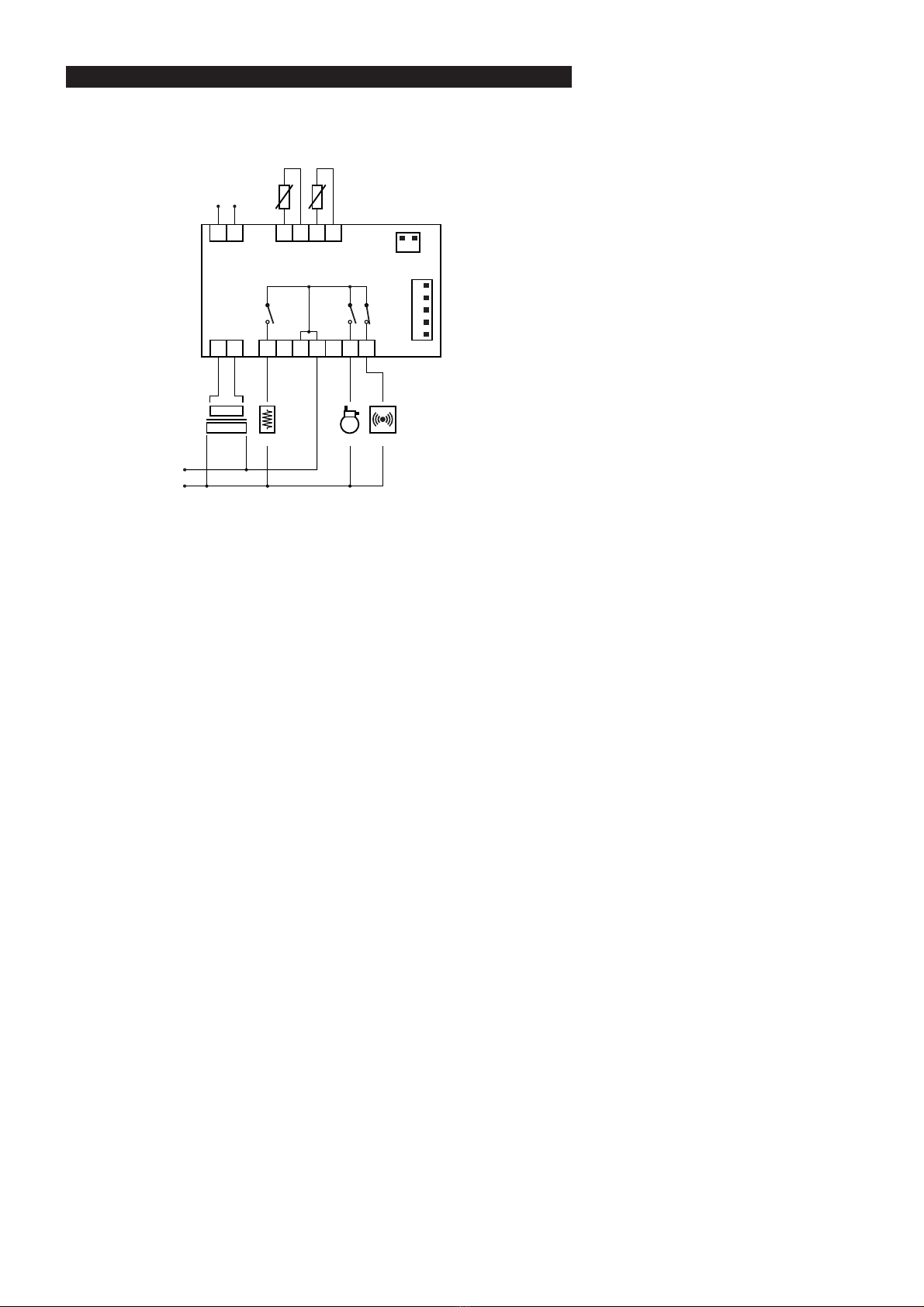
EWPX 195/E
11 12 15 16 17 18
TTL output
to the interface module
to TELEVIS system
thermostat
probe
defrost
probe
4 5 6 7 8 9 10
comp.
defrost
POWER SUPPLY
output to
the EWPX ECHO
signal repeater
–+
–
+
alarm
output evaporator
fans control
–
+
1 2
CONNECTIONS
This manual suits for next models
1
Other Siebe Group Company Controllers manuals

Popular Controllers manuals by other brands

cashco
cashco 1000HP Installation, operation & maintenance instructions

Novy
Novy 990030 operating instructions

Lipidex
Lipidex AirCycler SmartExhaust FV-WCPT1-W quick start guide

roco
roco ROCOMOTION 10785 quick start guide

Hamplus
Hamplus MBD-8F Operation manual

Johnson Controls
Johnson Controls VA-9070 Series Technical bulletin


