Siebeck MK III Series Operational manual
Translation of the original operating manual
No. 0411 FRT-A-MKIIIbed
JET 2000 tying machine
MK III series
FRT-A-SB and FRT-AS-SB model series
GMBH
Telephone +49 (0)6271 9208 0
e-mail : info@siebeck.de
69412 EBERBACH, GERMANY
Fax +49 (0)6271 9208 88
Internet : www.siebeck.de

Siebeck GmbH Translation of the original operating manual 0411 FRT-A-MKIIIbed
Page 2
Table of contents
Page
Hazard warnings................................................. 3
Introduction........................................................ 4
Warranty ............................................................. 5
EC declaration of conformity............................... 6
Technical data / Proper use………………………. 7
Safety.................................................................. 8
Safety instructions for transportation................... 9-11
Set-up and commissioning................................... 12-14
How the safety sensor works............................... 13
Fitting the foot pedal............................................ 15-16
Inserting the string............................................... 17-23
Operating controls................................................ 24
Cleaning and maintenance ................................... 25-30
Tensioning and adjusting the conveyor belts.... 31-32
Maintenance.......................................................... 33-34
Setting the stripper ............................................... 35
Setting the zero position knotting aggregate……… 36-37
The story of knots................................................ 38-39
Faults and their causes.......................................... 40
Further maintenance instructions.......................... 41-42
Troubleshooting .................................................... 43
Residual risks and incorrect operation ................... 44-48
Display and operating screen
Spare parts list:
Mechanical assembly groups / electrical parts
Circuit diagrams

Siebeck GmbH Translation of the original operating manual 0411 FRT-A-MKIIIbed
Page 3
Hazard warnings
Hazard warnings are found in the respective position in the text.
They are denoted by this warning
triangle and an information text.
Caution!
The technical manual must have been read and understood
before using the machine for the first time. For personal
safety it is important to follow all the instructions listed in it.
Themanual must be kept bythe customer and must be
handed over in case the machine is passed on to third parties
or a newuser.
Caution!
Installation and repair must only be performed by qualified
persons who have the necessaryexperience and
knowledge of occupational and industrial safety and risks of
accidents. If the available staff do not have one or more of
these qualifications, specialist staff must be contracted.
Caution!
If it is necessaryto replace a components, you must
make sure that only original spare parts are used.
Improper repairs or the use of non-original spare parts
can cause considerable damage and hazards for the
user.
In case of damage which has be caused by failure to observe this operating
manual, the warranty will be rendered null and void. No liability will be
assumed for consequential damages.
No liability will be assumed in case of material damages or personal injuries
which are caused by improper use or failure to adhere to the safety
instructions.

Siebeck GmbH Translation of the original operating manual 0411 FRT-A-MKIIIbed
Page 4
Introduction
This machine has been engineered in accordance with the recognised rules
of technology and in adherence to the regulations for occupational safety and
the prevention of accidents so that proper use cannot not cause any
hazards for the life and limb of the user or third parties.
Information on incorrect use and residual risks, which are still in place or
possible despite the integrated safety and technical protective
equipment, are described and illustrated on pages 43-47. These risks are
documented in a risk analysis and filed by the manufacturer.
Every person on the user's premises given the task of
setting up, commissioning, operating, maintaining and
repairing this machine must have read and understood
this operating manual, and in particular the chapter
"Safety".
The customer's own changes, restrictions or upgrades and the resultant
safety-related consequences are at the expense and risk of the user.
If this machine is sold or set up at another location, this
operating manual must be handed over to the new owner or the
new user. Additional copies can be ordered from the address
given below, quoting article number 0411 FRT-A-MKIIIbed.
69401 Eberbach, Germany
Friedrichsdorfer Landstrasse 64
Telephone +49 (0)6271 9208 0
Fax +49 (0)6271 9208 88
E-mail : info@siebeck.de
Internet : www.siebeck.de

Siebeck GmbH Translation of the original operating manual 0411 FRT-A-MKIIIbed
Page 5
WARRANTY
All machines which have been manufactured at our production
facilities are covered by a warranty of 12 months, starting from the
date of commissioning, or 18 months from the date of delivery. This
warranty covers material and manufacturing faults.
The warranty covers all parts, with the exception of
expendable parts and parts which are replaced due to normal wear
during maintenance. Under the terms and conditions of the
warranty we are not liable for working hours and downtimes.
If machine damage is caused due to the use of unsuitable tying
material or material not expressly recommended by us, the warranty
will be rendered null and void.
All claims must be asserted in writing. An exact description of the
cause of damage, the part number and machine number must be
enclosed. Once we have accepted your warranty claim, the faulty
part must be returned to us.
This warranty is only valid if
original parts without any form of modification are used.

Siebeck GmbH Translation of the original operating manual 0411 FRT-A-MKIIIbed
Page 6
EC - Declaration of Conformity
We hereby declare that the supplied model of
Manufacturer : SIEBECK
Model:
Serial No. :
complies with the following provisions applying to it:
EC Machinery Directive 2006/42/EG
Applied harmonised standards, in particular:
EN ISO 12100-1
EN ISO 12100-2
EN 60204
EC Direktive Electromagnetic
compatibility 2004/108/EG
Safety of machinery; Basic concepts,
general principles for design, basic
terminologie, methodologie
Technical principles and specification
Safety of machinery; electrical
equipment of machines
Part 1: General requirements
Only for FRT and FRS machines
EN 1672
1935/2004/EC/GS-FW 01/01
Country of Origin
Person responsible for the
technical manual:
Eberbach, 16.05.2011
Siebeck GmbH
Food processing machinery /
Basic concepts /
Part 2: Hygiene requirements
Materials and articles intendet to come in to
contact with food
Federal Republic of Germany (European
Community)
Gunter Siebeck

Siebeck GmbH Translation of the original operating manual 0411 FRT-A-MKIIIbed
Page 7
Technical data
Machine performance: up to 60 cycles per minute
depending on the tying spacing
Machine weight: Infeed conveyor 125 kg
Outfeed conveyor 80 kg
Machine 180 kg
Total weight 385 kg
Noise pressure level: 79 dB(A) as per EN 11204
(without product / without string)
Connected elec.load: 170-260 volts / 1ph.alternat. current /
50-60 Hz / 1,6 kW
Compressed air: 50 litres per minute / 2 bar
Proper use: Tying food, in particular meat, fish,
poultry, vegetables etc.
All dimensions in mm / specifications are subject to change without notice
Compressed air
Elec.Power
400
170 - 260 V AC 1,6 KW 50/60 Hz
Power cable
Cable: 4G1,5/ 5mtr. long
1480 560 1480
3520
945
260 150
800
125
(880 FRT-AS-SB)
Comp.air
2 bar 50ltr./min.
Socket DN 7,2
1300 1385(1485 FRT-AS-SB)
Siebeck GmbH Translation of the original operating manual 0411 FRT-A-MKIIIbed
Page 8
Safety !
The European standard EN 60204-1 requires the power
supply connection to be established by a suitable plug device.
The power supply cable must not be connected to a power
distributor directly by way of a terminal connection, without a plug
connector.
Safety limit switch S1 prevents the machine from starting up when
the machine hood is open. This safety device must be checked
before putting the machine into operation each time to make
sure it is fully functional.
Procedure:
First switch on the machine and wait for the reference run to be performed (see
last paragraph below), open the hood, do not reach into the machine (!), then
press the foot pedal. The machine must not start up.
Monitoring switch B7 prevents the machine from starting up if the
dirt pan is removed or not fully inserted. This monitoring device
must be checked before putting the machine into operation each
time to make sure it is fully functional. Procedure as described
above.
Always pull the mains plug before all maintenance and cleaning
work!
When inserting a new string bobbin, and when threading the string,
always pull the mains plug.
Reference run
Once the machine has been switched on using the master switch (Q1), a check
is automatically performed to determine whether the preset reference points for
the ring and knotting aggregate drives are positioned correctly. This run
(duration approx, 10 seconds) is performed at reduced speed and ensures that
both drives are ideally synchronised with each other. The machine is ready for
operation on completion of this reference run.
A minimum of 500 lux is required for local lighting.

Siebeck GmbH Translation of the original operating manual 0411 FRT-A-MKIIIbed
Page
9
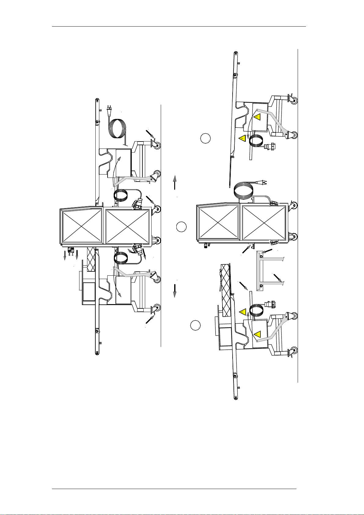
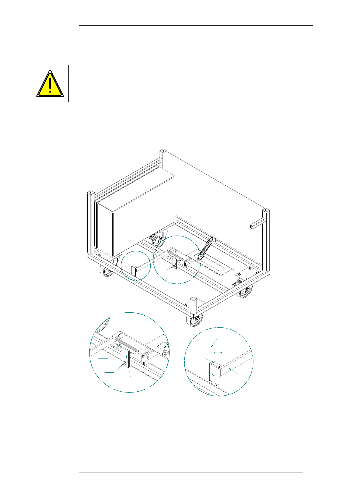
Safety instructions for transportation
The entire machine comprises three units which, once disconnected, can
be transported or shifted separately. See page 11 for a figure.
1 - Infeed conveyor (with vertical belts)
2 - Tying machine
3 - Outfeed conveyor
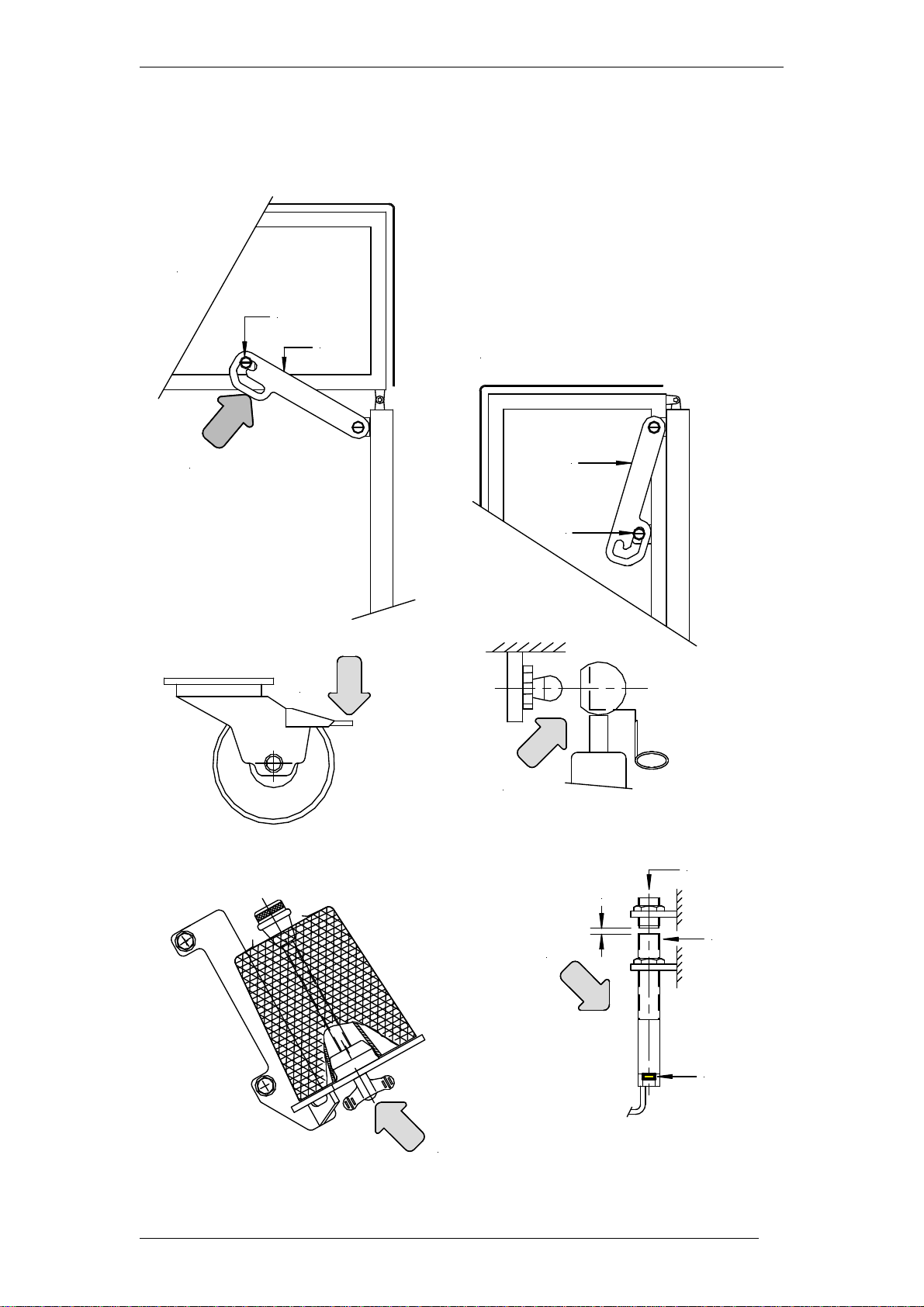
Procedure for disconnecting, e.g. for cleaning purposes:
Pull the mains plug (A)
Roll up the cable and keep it safe
Disconnect both the plug connections (B) between the belt and the machine.
Caution: First lift the cover on the socket in the direction of the arrow, turn the
grey ring clockwise, then pull the plug. Roll up the cable and keep it safe.
Unfasten both compressed air connections (C) using the quick
coupling. Roll up the air hose and keep it safe.
Unfasten the wheel locks (D) on the conveyors (2 on each) by pressing
them in the direction of the arrow.
Turn the pivot lever (E) in the direction of the arrow. The conveyors are now in
a slightly inclined position and can be pulled out of the machine in the
direction of the arrows (F) or (G).
Caution! The conveyors are slightly top-heavy. Do not run
them over thresholds or uneven floor. In case of a deflection of
>10°there is a risk of tilting over and thus a ris k of injuries !
After transporting the conveyors, fasten the wheels back in place with the
wheel locks (D).
When assembling, repeat the steps described above in reverse order. Make
sure that the connecting crossbeam (H) is in the correct position to the
mounting device (J) after inserting the conveyors.
Siebeck GmbH Translation of the original operating manual 0411 FRT-A-MKIIIbed
d
Page 10
Caution!
Because of the movement of the machine and the conveyors there is
a risk of impacts.
Caution! When lowering the conveyors using the pivot lever (E)
proceed with the upmost care. The weight of the conveyors causes
them to lower quickly and abruptly. Hold the pivot lever firmly in the
hand and lower the conveyors slowly. If lowered abruptly there is a
risk of crushing.
Caution!
There is a risk of crushing between the connecting crossbeam and the
mounting points J when lowering the conveyors.
After lowering, check whether the connecting crossbeam (H) is resting properly
in the mounting device (J). After transporting the conveyors, fasten the wheels in
place with the wheel locks (D).
Caution!
All supply lines (electrical connection cables and pneumatic hoses)
must be kept safe, both when transporting and when operating the
machine.
Siebeck GmbH Translation of the original operating manual 0411 FRT-A-MKIIIbed
Page 11
A
B
B
C
F G
1
2
3
D
E E
D
D
HJ
HJ
Siebeck GmbH Translation of the original operating manual 0411 FRT-A-MKIIIbed
Page 12
Set-up and commissioning
Mechanics
Erect the machine in the designated location and press the wheel locks
down so that the machine is stable (see page 14, fig. 2). In order to
transport the machine safely using a fork lift or lift truck, the foot pedal is
moved up into the machine frame before delivery.
See pages 15 and 16 for the procedure for installing the foot pedal.
Open the machine hood and check it to make sure it moves freely. Fig. A on
page 14 shows the machine hood open. Fig. B shows the machine hood
closed. When the machine hood is open, lug C engages with bolt D and thus
prevents the machine hood from falling uncontrolledly in case of a faulty
pneumatic pressure spring.
You must make sure at all times and check that lug C moves freely
and engages with bolt D after opening the machine hood.
When closing the machine hood the lug has to be pushed upwards in the
direction of arrow 1. The machine hood cannot be closed until you have
done so.
Never attempt to close the machine hood by force without
releasing the lug from the locking mechanism. This may
otherwise cause considerable machine damage.
Check that the M8 ball heads on the pneumatic pressure spring
are firmly in place and check that the securing wires on
the pneumatic pressure springs are properly in place (see page
14, Fig. 3).
Make sure that the wing nut which fastens the string bobbin on
the bobbin holder, is tightened sufficiently firmly (see page 14,
Fig. 4).
When closing the hood, make sure that the safety sensor is
positioned correctly to the actuator (4-5mm) (see page 14, Fig. 5).

Siebeck GmbH Translation of the original operating manual 0411 FRT-A-MKIIIbed
Page 13
To avoid collisions with other machines and to ensure operating and
maintenance staff have sufficient access, there must be minimum of
1.5 metres of clearance around the entire machine.
Electrical system:
If not otherwise stipulated, the machine is designed for 230 V 1-phase alternating
current 50/60 Hz when supplied from the factory. Measure the local mains
voltage and compare the measurement with the value specified on the type plate.
Check that the machine is correctly grounded. Adhere to the local
electrical engineering regulations. Maximum fuse protection 16
amperes. Connect the machine to the supply mains using a plug
connector. Switch on the master switch (Q1). The indicator lamp lights
up.
Once the reference run has been completed (see last paragraph on page 8), the
machine is ready for operation.
How the safety sensor woks
Mode of operation of the diagnostic LED
The green LED signals that the sensor is ready for operation. The sensor is not
actuated.
When the CSS 180 sensor is actuated by the CST 180 actuator, the LED changes
from green to yellow. The safety outputs switch to enable. If the actuator is near of
the limit of the sensor switching distance, the yellow LED flashes.
The safety outputs remain enabled. The sensor can be readjusted before the safty
outputs will be swiched off and stop the machine. Errors in the actuator coding or
the sensor outputs are signaled by a red flashing LED.
The safe outputs then switch off after a delay of 1 minute. An internal fault is
indicated by a continuous red LED and, if safe operation is not ensured, results in
an immediate disabling of the safety outputs.
Siebeck GmbH Translation of the original operating manual 0411 FRT-A-MKIIIbed
Page 14
4
2
3
5
4-5 mm
a
b
c
1
A
B
C
D
C
D

Siebeck GmbH Translation of the original operating manual 0411 FRT-A-MKIIIbed
Page 15
x
y
x
c
c
b
b
a
1. Unscrew the panelling from the front.
2. Remove both cable ties (x).
3. Insert the rotary axle (a) on the foot pedal into the elongated holes
(b) of both lugs (c). The tension spring (y) does not need to be
removed for this process.
4. Unfasten the hexagon screw (e) and move the lug (d) into the
vertical position and tighten the hexagon screw (e) again.
Fitting the foot pedal
Siebeck GmbH Translation of the original operating manual 0411 FRT-A-MKIIIbed
Page 16
After fitting, check whether the limit switch (g) is correctly actuated by
the lug (f). When the foot pedal is actuated, the inner circle (h) of the
cross hairs must be covered. The gap between the limit switch (g) and
the lug (f) should not be greater than 3mm. Adjust the position of the
limit switch using the lug (i) as necessary.
5. Screw the panelling back on.
ed
d
e
if
g
3
max
h
a
Detail B
B
a
Detail C
C
Detail B
Detail C

Siebeck GmbH Translation of the original operating manual 0411 FRT-A-MKIIIbed
Page 17
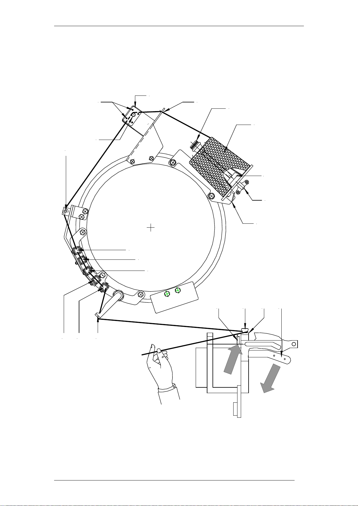
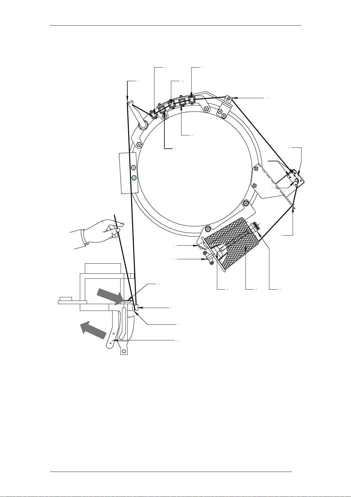
Inserting the string
When the machine leaves our premises, it includes a piece of string
completely threaded. Study the course of the string exactly to make
understanding the following description easier.
Proceed as follows in accordance with the threading diagram opposite:
Pull the mains plug and open the machine
hood
-Remove the wing nut (B) and the threaded rod (E).
-Insert the threaded rod (E) through the string bobbin (D) from above.
Place the string bobbin (D) together with the threaded rod (E) on the
bobbin holder (A). Guide the bottom end of the threaded rod (E)
through the drilled hole on the mandrel (C) and screw on and tighten
the wing nut (B). You must make sure that the string bobbin's
cardboard tube rests firmly on the mandrel (C) and that the net which
surrounds the string bobbin is securely clamped between the cardboard
tube and the mandrel (C).
-Feed the lead end of the string through the drilled hole (F).
-Insert the string in the thread brake (G). Make sure that the string
comes to rest between both pins (H) and the shaft of the hexagon
screw (I) (see figure).
-The next string guides are rollers. Thread the string in numerical order:
2 Roller on the take-up lever arm mount
3 First roller on the tying arm mount
4 First roller on the take-up lever arm
5 Second roller on the tying arm mount
6 Second roller on the take-up lever arm
7 Last roller on the tying arm mount
Guide the string through the insert (K) at the end of the tying arm tube.
Inserting the string in the knotting aggregate:
Use your left hand to wrap the string around the twine holder button
(L) upwards from below. Use the right hand to actuate the twine
holder button lifting lever in the direction of the arrow. Whilst you
hold the string tight with the left hand, the string enters between the
twine holder button (L) and the clamping head housing (P). The string is
clamped once you release the twine holder button lifting lever (M).
Use your right hand to push the knife trap lever (N) forwards in the
direction of the arrow; the string is cut off.
Close the machine hood, switch on the master switch. After the
reference run, the machine is ready for operation.
Check that the string rollers and the take-up lever move freely
and oil them as necessary.
Only use lubricants which are approved for the food sector
(see the chapter "Maintenance").
Siebeck GmbH Translation of the original operating manual 0411 FRT-A-MKIIIbed
Page 18
Threading diagram ( model FRT-A-SB )
N L P M
345
6 7 K
2
HGE
D
A
B
C
I
F
Siebeck GmbH Translation of the original operating manual 0411 FRT-A-MKIIIbed
Page 19
Threading diagram ( model FRT-AS-SB
)
2
3
4
5
6
7
K
L
P
N
M
A
B
C D E
F
G
I
H

Siebeck GmbH Translation of the original operating manual 0411 FRT-A-MKIIIbed
Page 20
Inserting the string ( F take-up lever )
When the machine leaves our premises, it includes a piece of string
completely threaded. Study the course of the string exactly to make
understanding the following description easier. Proceed as follows in
accordance with the threading diagram opposite:
-Remove the wing nut (B) and the threaded rod (E).
-Insert the threaded rod (E) through the string bobbin (D)
from above.
Place the string bobbin (D) together with the threaded rod (E)
on the bobbin holder (A). Guide the bottom end of the
threaded rod (E) through the drilled hole on the mandrel (C)
and screw on and tighten the wing nut (B). You must make
sure that the string bobbin's cardboard tube rests firmly on
the mandrel (C) and that the net which surrounds the string
bobbin is securely clamped between the cardboard tube and
the mandrel (C).
-Feed the lead end of the string through the drilled hole (F).
-Insert the string in the thread brake (G). Make sure that the
string comes to rest between both pins (H) and the shaft of
the hexagon screw (I) (see figure).
-The next string guides are rollers. Thread the string in
numerical order:
L1 - K2 - L3 - K4 - L5 - K6 - L7 – M
Guide the string through the insert (N) at the end of the tying
arm tube. Inserting the string in the knotting aggregate:
Use your left hand to wrap the string around the twine holder
button (O) upwards from below. Use the right hand to
actuate the twine holder button lifting lever (P) in the
direction of the arrow. Whilst you hold the string tight with
the left hand, the string enters between the twine holder
button (O) and the twine holder button housing (R). The
string is clamped once you release the twine holder button
lifting lever (P). Use your right hand to push the knife trap
lever (S) forwards in the direction of the arrow; the string is
cut off. Close the machine hood, switch on the master
switch. After the reference run, the machine is ready for
operation.
Check that the string rollers and the take-up lever move freely
and oil them as necessary.
Only use lubricants which are approved for
the food sector (see the chapter
"Maintenance").
This manual suits for next models
2
Table of contents


