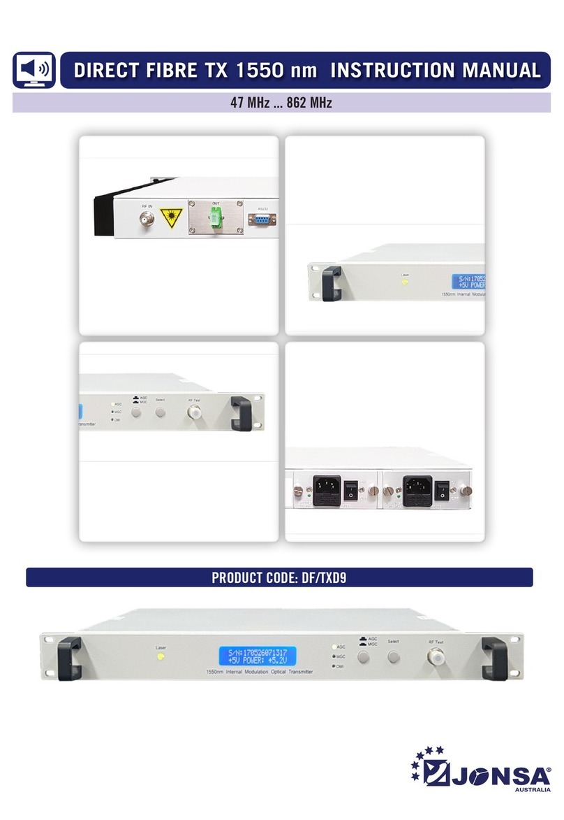
Jonsa DF/TXDG12 User manual

®
AUSTRALIA
PRODUCT CODE: DF/TXDG12
47 MHz ... 2400 MHz
DIRECT FIBRE TV TRANSMITTER 1550 nm INSTRUCTION MANUAL

2 3
DIRECT FIBRE TV TRANSMITTER 1550 nm [47 MHz ... 2400 MHz]
SAFETY PRECAUTIONS
WARNING: Avoid personal injury and product damage by complying with the following important
operating and maintenance instructions.
Avoid Electric Shock
WARNING: To reduce the risk of an electric shock, perform only the instructions that are included in
this instruction manual. Refer all servicing to a qualified service technician.
Do not apply power to the TX until all components have been installed and all of the wiring has
been properly terminated. Failure to do so may result in damage to the product and this will void the
manufacturer’s warranty.
Do not attempt to terminate, change or un-install any of the wiring without first switching off the unit
and unplugging the AC power cord from the TX. Be sure to switch off the power at the outlet and the
TX prior to disconnecting or unplugging the power cords from the unit.
The voltage supplied must be at the recommended VAC, otherwise the TX could suffer irreparable
damage and subsequent invalidation of the warranty.
Note:
•Do not connect the TX to the power if the power cord is damaged
•Do not cut the AC power cords
Servicing
WARNING: Avoid electric shock! Opening or removing the cover may expose you to dangerous
voltages. Do not open the cover of this product and attempt service unless instructed to do so in the
operating instructions. Refer all servicing to qualified personnel only.
Laser Safety
CAUTION
VISIBLE AND INVISIBLE LASER RADIATION
AVOID EXPOSURE TO THE BEAM
Grounding Terminal
WARNING: This product is equipped with an external grounding terminal, attach one end of a
2.5mm to the grounding terminal; then, attach the other end of the wire to an earth ground, such as
an equipment rack that is grounded or CET.

3
DIRECT FIBRE TV TRANSMITTER 1550 nm [47 MHz ... 2400 MHz]
CONTENTS
SAFETY PRECAUTIONS 2
CONTENTS 3
INTRODUCTION & SPECIFICATIONS 4
1.1 Product Overview 4
1.2 Features 4
1.3 Main Technical Specification Parameters 4
APPEARANCE 5
1.4 Front View 5
1.5 Bottom View 5
TROUBLESHOOTING 6
1.6 Troubleshooting 6
DIAGRAMS 6
1.7 Fibre Transmitter Diagram 6
1.8 Device Installation Diagram 6
1.9 System Installation Diagram 6
WARRANTY 7

1.1 Product Overview
This is an all-in-one direct fibre transmitter for the use in medium to large fibre distribution networks. It can be
used as a standalone Fibre Direct Transmitter or combined with our EYDFA.
This device provides long life stability and reliability.
1.2 Features
•Fibre output wavelength: 1550 nm ±10
•RF input: 47 MHz to 2400 MHz
•Fibre simultaneous dual outputs at + 12 dBm and + 9 dBm
•Module design, simple installation
•Redundant power supply
•19" rack mounting in a 1RU space
•Low power consumption
1.3 Main Technical Specification Parameters
4 5
DIRECT FIBRE TV TRANSMITTER 1550 nm [47 MHz ... 2400 MHz]
INTRODUCTION & SPECIFICATIONS
Specifications
DF/TXDG12
Optical Power (mW) 15.85 7.95
Optical Power (dBm) 12 9
Optical Wavelength (nm) 1550 ± 10
Fibre Connection SC/APC
RF Bandwidth (MHz) 47 ... 2400
Channels 70 [Mix of DVB-C, DVB-T and DVB-S/S2]
Band Unflatness ≤0.75
Optical Modulation Mode Direct
Optical Return Loss ≥50
RF Input Level (dBµV) 70 ± 2 @ AGC
Input Return Loss ≥10
Input Impedance (Ω)75
CNR (dB) ≥51
CTB (dB) ≥65
CSO (dB) ≥65
Power Consumption (W) ≤4
Dual Power Supply (V) 110 VAC ... 254 VAC or 48 VDC
Storage Temperature (°C) - 10 ... + 50
Operation Temperature (°C) 0 ... + 50
Humidity (%) 20 ... 85
Dimensions (mm) 483 x 370 x 44

Name Function
Power A LED ON: Working Normally | LED FLASHING: Abnormal or No Power
Power B LED ON: Working Normally | LED FLASHING: Abnormal or No Power
SYS-WAR LED ON: Working Normally | LED FLASHING: Laser Output Lower than Normal Value (SYS-WAR = SYSTEM WARNING)
Menu LCD Menu Toggle Button
5
DIRECT FIBRE TV TRANSMITTER 1550 nm [47 MHz ... 2400 MHz]
APPEARANCE
1.4 Front Panel
Key Number LCD (Display) Line Description
0DF/TXDG12 DF/TXDG12 is the Product Code / Model of the Fibre Optical Direct Transmitter
S/N: 20180818002 Indicates the Serial Number of the Device
1OP_A Pow: The output power of laser A.
Bias1: The laser A bias current.
2A+5V: PSU A +5V Status. If the voltage is < + 4.2 V, "LOW" is displayed, if above + 5.8 V, "High" is diplayed
A-5V: PSU A -5V Status. If the voltage is < - 5.8 V, "LOW" is displayed, if above 5.8 4 V, "High" is diplayed
3B+5V: PSU B +5V Status. If the voltage is < + 4.2 V, "LOW" is displayed, if above + 5.8 V, "High" is diplayed
B-5V: PSU B -5V Status. If the voltage is < - 5.8 V, "LOW" is displayed, if above 5.8 4 V, "High" is diplayed
4DF/TXDG12 DF/TXDG12 is the Product Code / Model of the Fibre Optical Direct Transmitter
Soft Ver:1.0.0.1 Software Version loaded in the Fibre Transmitter
Name Function
Grounding Terminal, Connect to Earth [CET]
Laser Out (+ 9 dBm) + 9 dBm Fibre Optic Signal Output SC/APC Connector
Laser Out (+ 12 dBm) + 12 dBm Fibre Optic Signal Output SC/APC Connector
RF Input RF Signal Input: 47 MHz to 2400 MHz, F Female Connector
Back Up Back up Power Supply Module
Main Main Power Supply Module
1.5 Rear Panel

1.7 Fibre Transmitter Diagram
PUMP
RF INPUT
70 ± 2 dBµV
OPT
LCD
& KEY
CPU
POWER A
MAIN
POWER B
BACK UP
+ 9 dBm OUTPUT
+ 12 dBm OUTPUT
1.9 System Installation Diagram
STB &/OR
RF DISTRIBUTION
NETWORK
INTERNET
SERVICE
EYDFA
ONE
PON
SATELLITE
FIBRE
RECEIVER
FIBRE
OPTIC
MODEM
SATELLITE
FIBRE
TRANSMITTER
MULTIPLE
PON'S
RF
INPUT
1.8 Device Installation Diagram
CONNECT
GROUND WIRE
& POWER CORD
TURN
ON
DEVICE
INSTALLING
THE FIBRE
TRANSMITTER
CONNECT
SIGNAL
CABLES
ACQUISITION
CHECK
+ 12 dBm
OUTPUT
+ 9 dBm
OUTPUT
POWER
SWITCH
6 7
DIRECT FIBRE TV TRANSMITTER 1550 nm [47 MHz ... 2400 MHz]
1.6 Troubleshooting
1. Q. The LED indicator for Power A or Power B is flashing?
A. Check the power cord inputs and ensure the switch on the power outlet along with the device is
switched on.
2. Q. The LED indicator for SYS-WAR is off.
A. Check the laser output power using a Fibre Power Meter, this indicates a lower than nominal output.
TROUBLESHOOTING
DIAGRAMS
CAUTION: DO NOT FEED THE + 12 dBm FIBRE OPTICAL OUTPUT INTO THE EYDFA INPUT!
THIS MAY CAUSE DAMAGE TO THE EYDFA.

7
DIRECT FIBRE TV TRANSMITTER 1550 nm [47 MHz ... 2400 MHz]
Please keep a copy of your proof of purchase with this Instruction Manual / Warranty.
DO NOT SEND BACK TO JONSA AUSTRALIA
PLEASE READ THIS WARRANTY AND KEEP IT WITH YOUR PURCHASE RECEIPT
Please complete these details and retain your original proof of purchase as you will require both documents
to claim this as a warranty repair. Keep the documents in a safe place for future reference should you need to
return this product to your place of purchase, during the warranty period of up to 12 months from the date
of purchase.
Customer Details
Name First Name Serial Number
Surname
Address Name [St, Ave, Drv etc] State
Suburb Post Code
Dealer or Installer Details
Name First Name Serial Number
Surname
Address Name [St, Ave, Drv etc] State
Suburb Post Code
Please Note:
• Beforemakingaclaimonthisproduct,pleasecheckyourInstructionManual.Youwillhavetopay
attention to non-product problems and operator errors.
• Thiswarrantydoesnotcoverfaultsbytheownersmisuse,includingbutnotlimitedtodamagefromshock,
or from foreign substances such as dirt or liquid entering the product.
ATTACH YOUR PROOF OF PURCHASE HERE...
WARRANTY

Version V1.3
Copyright © Jonsa Australia Pty Ltd. All Rights Reserved.
WA branch
Unit 1,
7 Mallaig Way,
Canning Vale
WA 6155
Australia
saleswa@jonsa.com.au
PO Box 6147,
Silverwater
NSW 1811
Australia
Head Office
Lidcombe Business Park,
Unit D2,
3 - 29 Birnie Avenue,
Lidcombe
NSW 2141
Australia
®
AUSTRALIA
Table of contents
Other Jonsa Transmitter manuals