ATSC 1KW DTV TX User Manual
ACT-1000-USR-DOC-V1.11, 09/12/2014 Page 20 of 73
8 Theory of Operation
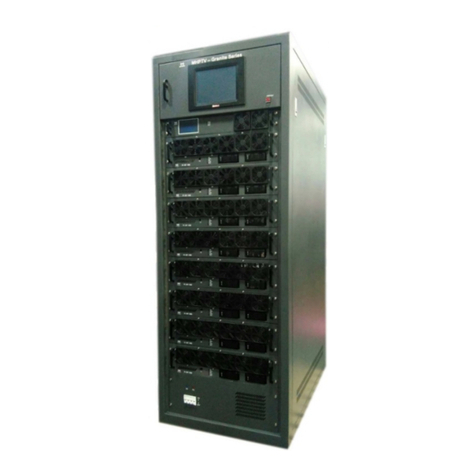
The ATSC 1000W DTV transmitter is conceptually simple to understand and easy to operate.
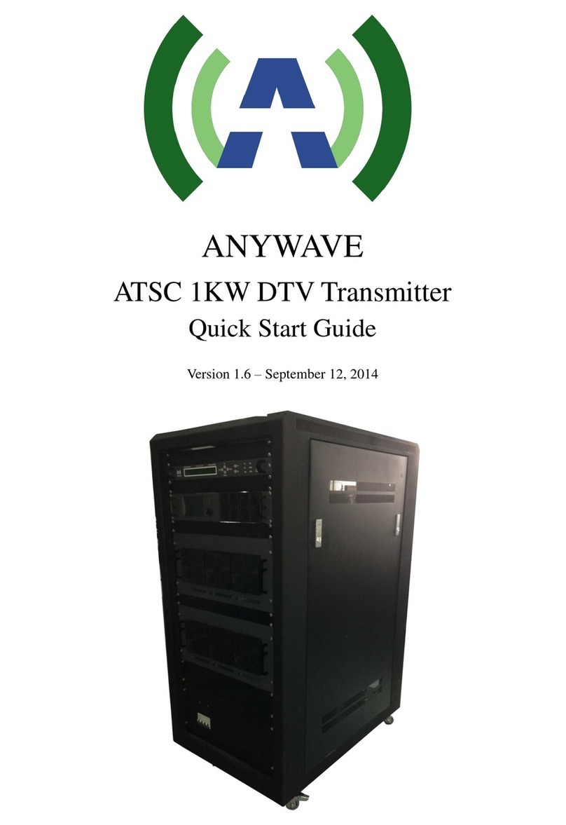
The Transmitter operates on 220VAC single-phase 30AAC Mains service.An AC Mains
Distribution compartment is located in the back rear floor of the TX. This compartment is shielded
for personnel safety and provides the distribution of appropriate AC power to the various modules
inside the TX cabinet.
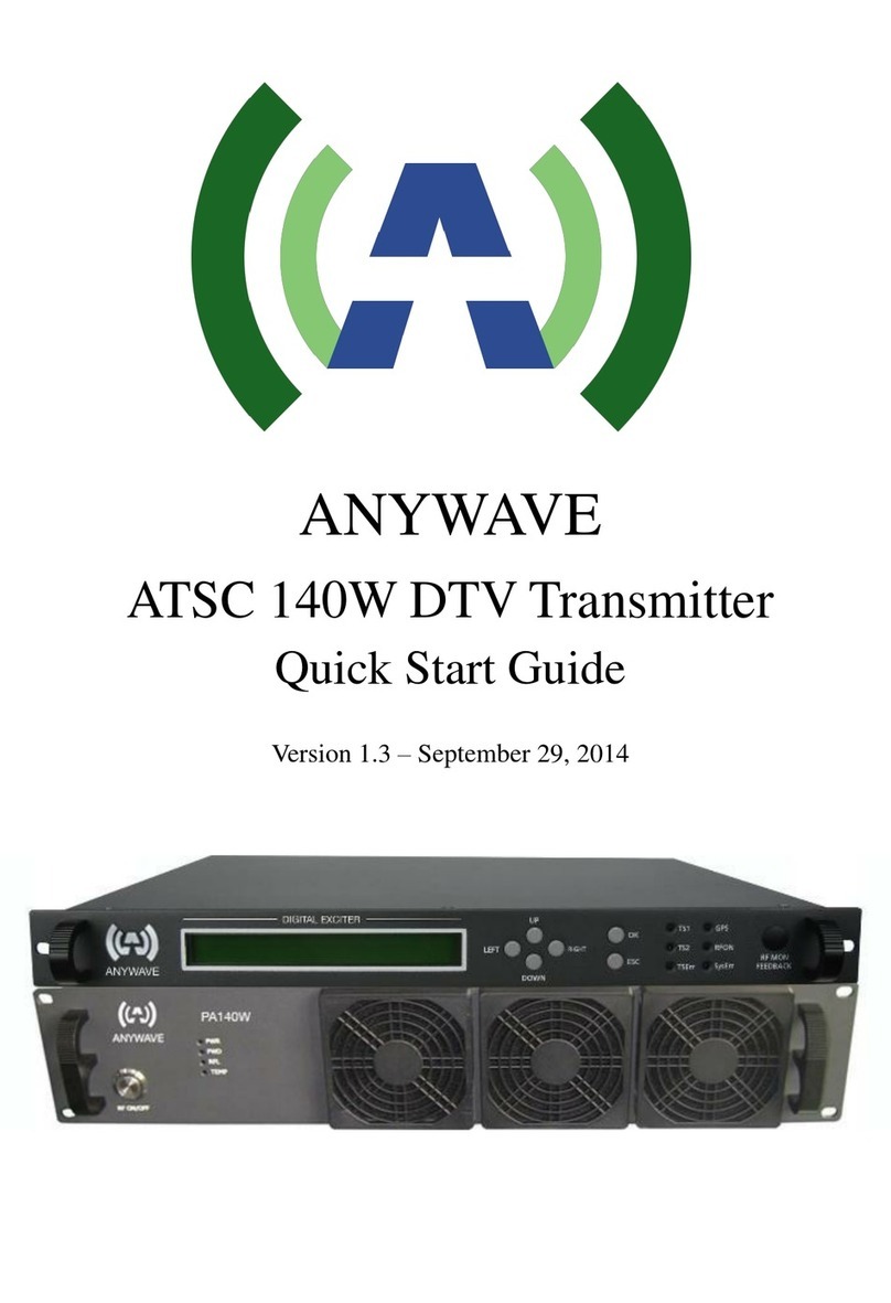
A standardATSC ASI input stream is provided to one of the BNC connectors located on the
rear panel of the Exciter. The Exciter (different platforms) supports options for DVB-ASI and
SMPTE310M stream formats as well as an RF off-air input via a built-in tuner and TSoIP support
via an RJ-45 input. The Exciter performs the appropriate FEC and Signal Processing to modulate a
standard 19.39 Mbps ATSC TS to produce an RF output at the desired channel frequency.
SupportedATSC modulation standards includeA/53 (Legacy),A/153 (MH), and A110:20011
(SFN).
The TX supports both Single and Dual Drive (DD) Exciter configurations, and manages the
automatic and manual switchover between Exciters in a DD configuration. The modulated RF
output signal from the Exciter(s) is (are) fed into the Control module which contains a 50W
preamp driver (1xBLF571 device driving 2xBLF881 transistors in parallel). The output of the
Controller preamp is then split and fed to the RF inputs of each of the PA modules.
The PA modules contain 4x BLF888Adevices that amplify the RF signal to produce 600W of
output power per PA. The amplified output signals of the two PAs are fed into a 2-way Hybrid
Combiner and then into a Directional Coupler and finally out the top of the cabinet via a section of
1 5/8 transmission line.
The 1 5/8 output stack of the Transmitter is then fed into an inline 1 5/8 Harmonic Filter (if
required) before entering a channel mask BPF. The output of the BPF connects to the Antenna
feed to radiate the DTV signal on-air.
The Exciter receives two feedback signals from FWD and REV couplers located at the BPF
input and output. These before and after BPF feedback signals are used by the Exciter to provide
automatic Linear and Non-Linear pre-correction of the ideal 8-VSB forward path signal.
Additional feedback signals are provided to the Control module, which monitors these
samples to implement protective protocols including forward power reduction and shutting down
the TX in the event of high reflected power or other unsafe operating conditions. System FWD
and REV power samples are provided to the Control module from the Directional Coupler located
directly after the 2-way power combiner. The Control module also receives a feedback sample