manuals.online logo
Brands
  1. Home
  2. •
  3. Brands
  4. •
  5. Dynisco
  6. •
  7. Transmitter
  8. •
  9. Dynisco 840 Series User manual

Dynisco 840 Series User manual

Other Dynisco Transmitter manuals

Dynisco SPX2 Series User manual

Dynisco

Dynisco SPX2 Series User manual

Dynisco MDT Series User manual

Dynisco

Dynisco MDT Series User manual

Dynisco 240 Series User manual

Dynisco

Dynisco 240 Series User manual

Dynisco SPX2 Series User manual

Dynisco

Dynisco SPX2 Series User manual

Dynisco PT460DN User manual

Dynisco

Dynisco PT460DN User manual

Dynisco IPX II Series User manual

Dynisco

Dynisco IPX II Series User manual

Dynisco PT303 User manual

Dynisco

Dynisco PT303 User manual

Dynisco EIT Series User manual

Dynisco

Dynisco EIT Series User manual

Dynisco SPX228 User manual

Dynisco

Dynisco SPX228 User manual

Dynisco TX180 User manual

Dynisco

Dynisco TX180 User manual

Popular Transmitter manuals by other brands

Seneca K120RTD installation manual

Seneca

Seneca K120RTD installation manual

Nautel GV40 installation manual

Nautel

Nautel GV40 installation manual

HumanTechnik cm-light operating instructions

HumanTechnik

HumanTechnik cm-light operating instructions

INOR APAQ C130 TC User instructions

INOR

INOR APAQ C130 TC User instructions

Linear DXS-64 operating instructions

Linear

Linear DXS-64 operating instructions

FeinTech ABT00102 instruction manual

FeinTech

FeinTech ABT00102 instruction manual

Geo Web Pack quick start guide

Geo

Geo Web Pack quick start guide

Inovonics EchoStream EN1210W installation instructions

Inovonics

Inovonics EchoStream EN1210W installation instructions

IKONNIK KA-6 quick start guide

IKONNIK

IKONNIK KA-6 quick start guide

Rohde & Schwarz SR8000 Series System manual

Rohde & Schwarz

Rohde & Schwarz SR8000 Series System manual

Audio Technica UniPak ATW-T93 Installation and operation

Audio Technica

Audio Technica UniPak ATW-T93 Installation and operation

NIVELCO EasyTREK SCA-300 Series Programming manual

NIVELCO

NIVELCO EasyTREK SCA-300 Series Programming manual

Honeywell 5816WMBR installation instructions

Honeywell

Honeywell 5816WMBR installation instructions

Kamstrup READy MTU Installation and operation guide

Kamstrup

Kamstrup READy MTU Installation and operation guide

Omega ZW Series user guide

Omega

Omega ZW Series user guide

ABB Field 264H Instructions for installation

ABB

ABB Field 264H Instructions for installation

Dejero EnGo 3x manual

Dejero

Dejero EnGo 3x manual

Rosemount 4600 Reference manual

Rosemount

Rosemount 4600 Reference manual

manuals.online logo
manuals.online logoBrands
  • About & Mission
  • Contact us
  • Privacy Policy
  • Terms and Conditions

Copyright 2025 Manuals.Online. All Rights Reserved.

OPERATINGMANUAL
840 Series840 Series
840 Series
StrStr
StrStr
Strain Gain G
ain Gain G
ain Gagag
agag
age Pre Pr
e Pre Pr
e Pree
ee
ess
ss
sss
ss
surur
urur
uree
ee
e TT
TT
Trr
rr
ranan
anan
ansmittsmitt
smittsmitt
smitterer
erer
erss
ss
s
Intrinsically safe and explosion proofIntrinsically safe and explosion proof
Intrinsically safe and explosion proof
pressure transmitters with integratedpressure transmitters with integrated
pressure transmitters with integrated
amplifier for use in hazardous environmentsamplifier for use in hazardous environments
amplifier for use in hazardous environments
P/N 974123
07/05 Rev. C
ECO # 30337
II 1GII 1G
II 1GII 1G
II 1G
AA
AA
ATEXTEX
TEXTEX
TEX 100a100a
100a100a
100a
OPERATINGMANUAL
TT
TT
TABLEABLE
ABLEABLE
ABLE
OFOF
OFOF
OF CC
CC
C
ONTENTSONTENTS
ONTENTSONTENTS
ONTENTS
ContentContent
ContentContent
Content PP
PP
Pagag
agag
agee
ee
eIconIcon
IconIcon
Icon
1. General 3
2. Notes on safety 5
3. Technical data 6
4. Function 15
5. Transport/delivery 16
6. Assembly 17
7. Commissioning 20
8. Maintenance 24
9. Troubleshooting 26
10. CE-Declaration of conformity 27
11. Ex-Declaration of conformity 28
3
GENERAL
1.1.
1.1.
1. GG
GG
GENERALENERAL
ENERALENERAL
ENERAL
1.1 Important information .......................................................................................................... 3
1.2 Copyright ............................................................................................................................. 3
1.3 Explanation of icons ............................................................................................................ 4
1.4 Abbreviations ...................................................................................................................... 4
1.5 Correct use .......................................................................................................................... 4
1.6 User’s obligations ................................................................................................................ 4
1.11.1
1.11.1
1.1 II
II
IMPORMPOR
MPORMPOR
MPORTT
TT
TANTANT
ANTANT
ANT
INFORMAINFORMA
INFORMAINFORMA
INFORMATIONTION
TIONTION
TION
This manual applies to the 840 series only. It must be kept near the equipment in a readily and
immediately accessible location at all times. The content of this manual must be read, understood and
followed in its entirety. This applies in particular to the notes on safety. Following the safety instructions
will help to prevent accidents, defects and malfunctions.
DD
DD
DYNISCYNISC
YNISCYNISC
YNISCOO
OO
O will not be held liable for any injury, loss or damage resulting from failure to follow the
instructions in this manual.
If the product malfunctions, in sptie of having followed the operating instructions, please contact the
DD
DD
DYNISCYNISC
YNISCYNISC
YNISCOO
OO
O customer service department (see the back of the manual for contact information).
1.21.2
1.21.2
1.2 CC
CC
COPYRIGHTOPYRIGHT
OPYRIGHTOPYRIGHT
OPYRIGHT
Copyright law requires that this manual be used for in-house purposes only.
It is strictly forbidden to allow reproduction of any kind “in whole or in part” to persons outside of
Dynisco.
4
GENERAL
1.1.
1.1.
1.33
33
3EE
EE
EXPLANAXPLANA
XPLANAXPLANA
XPLANATIONTION
TIONTION
TION
OFOF
OFOF
OF
ICIC
ICIC
ICONSONS
ONSONS
ONS
The manual uses icons to indicate information pertaining to safety:
Risk of destruction or damage to equipment, machines or installations
General danger to life or limb
Specific danger to life or limb
You MUST do this
The safety instructions are provided again in the individual chapters of the manual.
1.41.4
1.41.4
1.4 AA
AA
ABBREVIABBREVIA
BBREVIABBREVIA
BBREVIATIONSTIONS
TIONSTIONS
TIONS
The following abbreviations are used:
OMOM
OMOM
O M Operating manual
f.s.f.s.
f.s.f.s.
f.s. Of full scale
PTPT
PTPT
PT Pressure transmitter
1.1.
1.1.
1.55
55
5CC
CC
CORRECTORRECT
ORRECTORRECT
ORRECT
USEUSE
USEUSE
USE
The 840 series of pressure transmitters is specially designed for measuring pressure in explosive
atmospheres (safety class, EEx ia IIC T4, Ta=-20°C to +80°C) as part of a larger overall system. It
contains an integrated signal amplifier. The 840 series of pressure transmitters can be used in media
temperatures up to 85°C. If the pressure transmitter is used in other applications, the safety and
accident prevention regulations specific to that application must be followed.
When using the PT as a safety component in accordance with the EC Machine Directive,When using the PT as a safety component in accordance with the EC Machine Directive,
When using the PT as a safety component in accordance with the EC Machine Directive,
Annex IIc, the equipment manufacturer must take any necessary precautions to ensure thatAnnex IIc, the equipment manufacturer must take any necessary precautions to ensure that
Annex IIc, the equipment manufacturer must take any necessary precautions to ensure that
mm
mm
malfalf
alfalf
alfuu
uu
unctionnction
nctionnction
nctionss
ss
sofof
ofof
of the Pthe P
the Pthe P
the PTT
TT
Tcc
cc
cannotannot
annotannot
annot cc
cc
c
auau
auau
ause dse d
se dse d
se damam
amam
amagag
agag
age or injure or injur
e or injure or injur
e or injuryy
yy
y..
..
.
The 840 series of pressure transmitters are also designed for explosion proof areas approved by
factory mutual for Class I, Division 1, Groups A, B, C & D. Explosion proof models are also
approved for intrinsic safety by factory mutual for Class I, Division 1, Groups A, B, C, & D.
1.61.6
1.61.6
1.6 UU
UU
USS
SS
SERER
ERER
ER’’
’’
’SS
SS
S
OBLIGAOBLIGA
OBLIGAOBLIGA
OBLIGATIONSTIONS
TIONSTIONS
TIONS
The operator or owner of the larger overall system, e.g. a machine, is responsible for following the
safety and accident prevention regulations that apply to the specific application.
5
SAFETY
2.2.
2.2.
2. NN
NN
NOO
OO
OTETE
TETE
TESS
SS
S
ONON
ONON
ON
SS
SS
SAFETAFET
AFETAFET
AFETYY
YY
Y
The operator or owner of the larger overall system is responsible for following the safety
and accident prevention regulations that apply to the specific application.
When planning machinery and using the PT, follow the safety and accident prevention
regulations that apply to your application, e.g.:
• EN 60204, Electrical equipment in machines.
• EN 292, Machine safety, general design guidelines.
• DIN 57 100 Part 410, Protection against electric shock.
• EN 50 014:1997, General Requirements
• EN 50 020:1994, Intrinsically safe apparatus
• EN50284:1999, Special requirements fro Group II Category 1G
Mounting and electrical connection of the PT must be done by specialists with EMC training,
following all applicable regulations, and in pressureless, voltage-free, intrinsically safepressureless, voltage-free, intrinsically safe
pressureless, voltage-free, intrinsically safepressureless, voltage-free, intrinsically safe
pressureless, voltage-free, intrinsically safe
condition with the machine switched offmachine switched off
machine switched offmachine switched off
machine switched off.
The mThe m
The mThe m
The macac
acac
achine muhine mu
hine muhine mu
hine muss
ss
stt
tt
tbe secbe sec
be secbe sec
be securur
urur
ured aged ag
ed aged ag
ed againain
ainain
ainss
ss
stt
tt
tbeinbein
beinbein
being swg sw
g swg sw
g switit
itit
itcc
cc
ched bhed b
hed bhed b
hed bacac
acac
ackk
kk
kon!on!
on!on!
on!
Ambient temperature for the electronics housing mm
mm
max. +80°Cax. +80°C
ax. +80°Cax. +80°C
ax. +80°C (safety class T4 max.).
Higher temperatures can result in damage and malfunction. Do not install the pressure
transmitter in places where this temperature is exceeded.
ExpExp
ExpExp
Explolo
lolo
loss
ss
sion hion h
ion hion h
ion hazaz
azaz
azarar
arar
ard!d!
d!d!
d!
Deviation of the supply voltage from the value given in the technical specifications, or
false polarity, can damage the pressure transmitter and cause malfunctions that can
pose a risk of explosion.
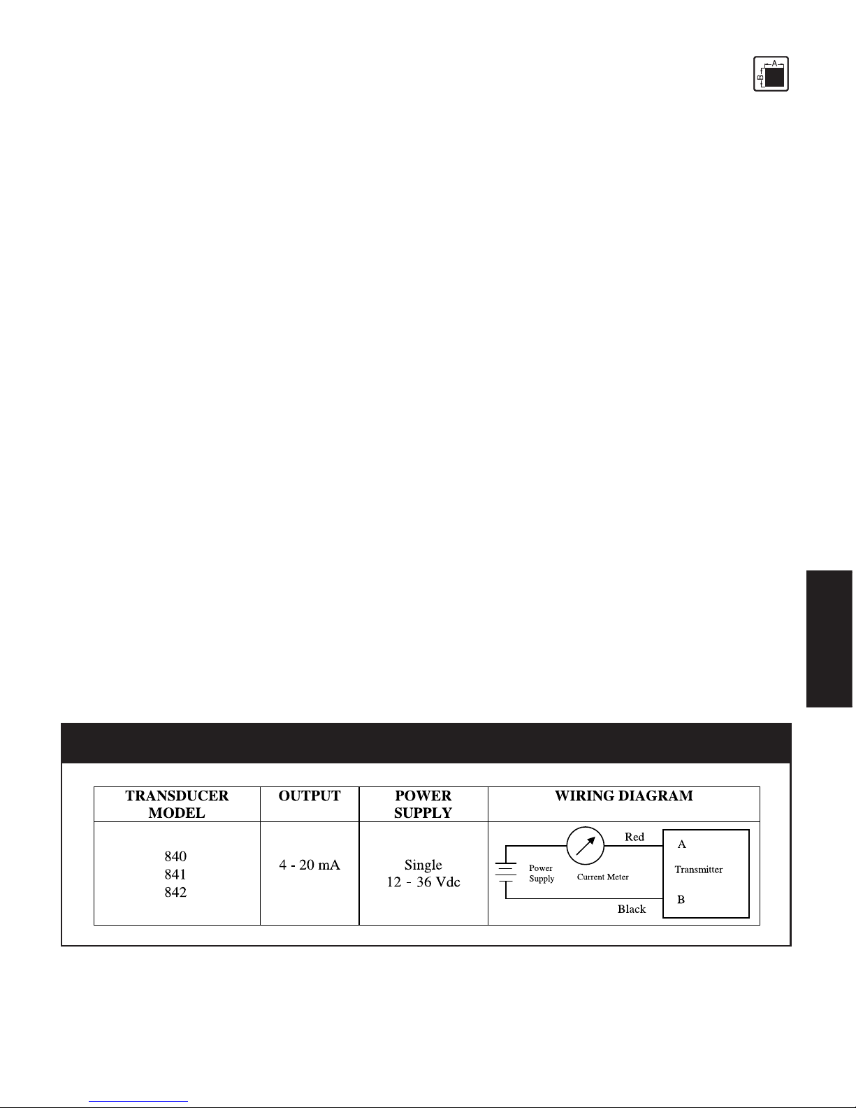
Operate only with an intrinsically safe, EMC compliant power supply with the
following specifications when employing the pressure 4-20mA output:
Supply voltage max.40 V DC
Current output max. 100 mA
Inductivity max. 0
Capacity max. 0.017 µF
For PT’s that are explosion proof Class I, Division 1, Groups A, B, C & D, the power
supply rating is 16-40 Vdc.
Do not lay connecting cables in the direct vicinity of cables carrying higher voltage or
used to switch inductive or capacitive loads.
6
TECHNICALDATA
3.3.
3.3.
3. TT
TT
TEE
EE
ECHNICALCHNICAL
CHNICALCHNICAL
CHNICAL DD
DD
D
AA
AA
ATT
TT
TAA
AA
A
3.1 Ordering guides ................................................................................................................... 6
3.1.1 Ordering guide for x84xx .................................................................................................... 6
3.2 Ordering example ............................................................................................................... 7
3.3 Safety related specifications................................................................................................7
3.4 Performance characteristics ................................................................................................. 7
3.4.1 Accuracy ............................................................................................................................. 7
3.4.2 Resolution ............................................................................................................................ 8
3.4.3 Repeatabilty ........................................................................................................................ 8
3.5 Pressure side connection ...................................................................................................... 8
3.6 Electrical Termination .......................................................................................................... 8
3.7 Wiring ................................................................................................................................. 9
3.8 Pressure ranges .................................................................................................................. 10
3.8.1 Max. Overload .................................................................................................................. 10
3.8.2 Burst pressure ..................................................................................................................... 10
3.8.3 Natural frequency .............................................................................................................. 10
3.9 Electrical Data .................................................................................................................. 10
3.10 Temperature influence ....................................................................................................... 1 1
3.11 EMC requirements ............................................................................................................. 1 1
3.12 Materials ........................................................................................................................... 1 1
3.13 Environmental Protection .................................................................................................. 12
3.14 Weight............................................................................................................................... 12
3.15 Dimensions ........................................................................................................................ 12
3.13.1
3.13.1
3.1 OO
OO
ORDERINGRDERING
RDERINGRDERING
RDERING
GUIDESGUIDES
GUIDESGUIDES
GUIDES
The exact meanings of the letter/digit combinations are given in the corresponding sections of
chapter 3.
3.1.13.1.1
3.1.13.1.1
3.1.1 OO
OO
ORDERINGRDERING
RDERINGRDERING
RDERING
GUIDEGUIDE
GUIDEGUIDE
GUIDE
FORFOR
FORFOR
FOR
XX
XX
X8484
8484
84XXXX
XXXX
XX
7
TECHNICALDATA
3.23.2
3.23.2
3.2 OO
OO
ORDERINGRDERING
RDERINGRDERING
RDERING EE
EE
E
XAMPLEXAMPLE
XAMPLEXAMPLE
XAMPLE
3.33.3
3.33.3
3.3 SS
SS
SAFETAFET
AFETAFET
AFETYY
YY
Y
RELARELA
RELARELA
RELATEDTED
TEDTED
TED
SS
SS
SPEPE
PEPE
PECIFICACIFICA
CIFICACIFICA
CIFICATIONSTIONS
TIONSTIONS
TIONS
ATEX certificate No.: SIRA 03ATEX2422
EX-Safety class EEx ia IIC T4 (Ta = -20°C to +80°C)
FM approvals Class I, Division 1 Groups A, B, C & D
CC
CC
Cerer
erer
ertified mtified m
tified mtified m
tified maxax
axax
aximumimum
imumimum
imum vv
vv
valuealue
aluealue
aluess
ss
sff
ff
for EExor EEx
or EExor EEx
or EEx ii
ii
ia IICa IIC
a IICa IIC
a IIC
T4T4
T4T4
T4
Associated electrical equipment must satisfy the following conditions:
Supply voltage max. 40 V DC
Current output max. 100 mA
Inductivity max. 0
Capacity max. 0.017 µF
3.43.4
3.43.4
3.4 PP
PP
PERFORMANCERFORMANC
ERFORMANCERFORMANC
ERFORMANCEE
EE
E
CHARACHARA
CHARACHARA
CHARACTERISCTERIS
CTERISCTERIS
CTERISTICTIC
TICTIC
TICSS
SS
S
x84xx - xxx - xx - xxx@xxx
3.4.13.4.1
3.4.13.4.1
3.4.1 AA
AA
ACC
CC
CCC
CC
CURAURA
URAURA
URACYCY
CYCY
CY
(Linearity, hysterisis and repeatability)
3.4.13.4.1
3.4.13.4.1
3.4.1AA
AA
AXX
XX
X840840
840840
840
±0.50% of full scale
3.4.13.4.1
3.4.13.4.1
3.4.1BB
BB
BXX
XX
X841841
841841
841
±0.25% of full scale
8
TECHNICALDATA
3.4.13.4.1
3.4.13.4.1
3.4.1CC
CC
CXX
XX
X842842
842842
842
±0.15% of full scale
3.4.23.4.2
3.4.23.4.2
3.4.2 RR
RR
RESOLUTIONESOLUTION
ESOLUTIONESOLUTION
ESOLUTION
Infinite
3.4.33.4.3
3.4.33.4.3
3.4.3 RR
RR
REPEAEPEA
EPEAEPEA
EPEATT
TT
TABILITABILIT
ABILITABILIT
ABILITYY
YY
Y
±0.10% of full scale
3.53.5
3.53.5
3.5 PP
PP
PRESSURERESSURE
RESSURERESSURE
RESSURE
SIDESIDE
SIDESIDE
SIDE
CONNECTIONCONNECTION
CONNECTION
The pressure port thread of the standard 840 Series (Code 0 in the model number) is internal 1/8 - 27
NPT fabricated from high strength stainless steel.
Options available include the following:
Code in Model No.Code in Model No.
Code in Model No. DescriptionDescription
DescriptionDescription
Description
0 ................................... 1/8 - 27 NPTF, internal
1 ................................... 1/4 - 18 NPT, internal
2 ................................... 7/16 - 20 UNF, internal, O-ring, per MS33649-4
3 ................................... High Pressure, internal fitting per autoclave F-250-C
4 ................................... 1/4 - 18 NPT, external
5 ................................... 1/2 - 14 NPT, external
6 ................................... 7/16 - 20 UNF, external, per MS33656-4
7 ................................... R 1/4 - metric, external
8 ................................... 3/4 - 16 UNF, external, flush diaphragm**
9 ................................... Special (consult factory)
A ................................... 1/2 - 14 BSP, external
B ................................... 7/16 - 14 NPSM, external
C ................................... Autoclave F-562-C
D .................................. 1” BSP, internal
G .................................. Autoclave F-375C
** Each flush diaphragm transducer or transmitter is shipped with a DYNASEAL, Dynisco P/N
633014, for the pressure port seal. Recommended torque, for an adequate seal, is 100 in-lbs. Care
should be exercised with the low pressure ranges. The flush diaphragm can be inadvertently
overloaded with thumb pressure, which can be the equivalent of several hundred psi.
3.63.6
3.63.6
3.6 EE
EE
ELELE
LELE
LECTRICALCTRICAL
CTRICALCTRICAL
CTRICAL
TT
TT
TERMINAERMINA
ERMINAERMINA
ERMINATIONTION
TIONTION
TION
The electrical terminations of the standard 840 series (Code 4 in the Model Number) is 2 wire, 4”
9
TECHNICALDATA
long leads and a 1/2 - 14 NPT conduit fitting fabricated from high strength stainless steel.
Options available include the following:
Code in Model No.Code in Model No.
Code in Model No. DescriptionDescription
DescriptionDescription
Description
0 ................................... PT02A-10-6P
1 ................................... PT02H-10-6P, hermetically sealed
2 ................................... PT1H-10-6P, hermetically sealed
3 ................................... 4’ six conductor wire, 1/2 - 14 conduit fitting
4 ................................... 42” two conductor wire with ground, 1/2 - 14 conduit fitting
5 ................................... 30’ two conductor wire with ground, 1/2 - 14 conduit fitting
9 ................................... Special (consult factory)
3.73.7
3.73.7
3.7 WW
WW
WIRINGIRING
IRINGIRING
IRING
The wiring of the standard 840 series (Code 4 in the Model Number) is 2 wire red and black.
Options available include the following:
Code in Model No.Code in Model No.
Code in Model No. DescriptionDescription
DescriptionDescription
Description
0 ................................... Connector (see above)
1 ................................... DHF/DV (BLH) wiring
2 ................................... Six conductor wiring
3 ................................... Six conductor DHF/DV (BLH) wiring
4 ................................... 2 wire red and black
5 ................................... 2 wire A and B
6 ................................... 2 wire white and black
9 ................................... Special (consult factory)
Fig. 3-1Fig. 3-1
Fig. 3-1Fig. 3-1
Fig. 3-1 PP
PP
Poo
oo
oww
ww
werer
erer
er SS
SS
Supup
upup
uppp
pp
plyly
lyly
ly RR
RR
Requirequir
equirequir
equirementement
ementement
ement andand
andand
and TT
TT
Typicypic
ypicypic
ypicalal
alal
al
WW
WW
Wirinirin
irinirin
iring Dig Di
g Dig Di
g Diagragr
agragr
agramam
amam
am
10
TECHNICALDATA
3.83.8
3.83.8
3.8 PP
PP
PRESSURERESSURE
RESSURERESSURE
RESSURE
RANGESRANGES
RANGESRANGES
RANGES
Model numberModel number
Model number PP
PP
Permittermitt
ermittermitt
ermitted pred pr
ed pred pr
ed pree
ee
ess
ss
sss
ss
surur
urur
ure re r
e re r
e ranan
anan
angg
gg
ge in Pe in P
e in Pe in P
e in PSISI
SISI
SI
x84xx-xxx-2.5C 0-250
x84xx-xxx-5C 0-500
x84xx-xxx-1M 0-750
x84xx-xxx-1.5M 0-1,000
x84xx-xxx-2.5M 0-1,500
x84xx-xxx-3M 0-3,000
x84xx-xxx-5M 0-5,000
x84xx-xxx-7.5M 0-7,500
x84xx-xxx-10M 0-10,000
x84xx-xxx-15M 0-15,000
x84xx-xxx-20M 0-20,000
x84xx-xxx-30M 0-30,000
x84xx-xxx-35M 0-35,000
x84xx-xxx-40M 0-40,000
x84xx-xxx-50M 0-50,000
x84xx-xxx-60M 0-60,000
3.8.13.8.1
3.8.13.8.1
3.8.1 MM
MM
MAXAX
AXAX
AX. O. O
. O. O
. OVERLVERL
VERLVERL
VERLOO
OO
OADAD
ADAD
AD ((
((
(
WITHOUTWITHOUT
WITHOUTWITHOUT
WITHOUT
INFLINFL
INFLINFL
INFLUENCINGUENCING
UENCINGUENCING
UENCING
OPERAOPERA
OPERAOPERA
OPERATINGTING
TINGTING
TING
DD
DD
DAA
AA
ATT
TT
TAA
AA
A))
))
)
x84xx 250-30,000 psi: 1.5x rated pressure
35,000-60,000 psi: 1.2x rated pressure
3.8.23.8.2
3.8.23.8.2
3.8.2 BB
BB
BURSTURST
URSTURST
URST
PRESSUREPRESSURE
PRESSUREPRESSURE
PRESSURE
250 psi: 10x rated pressure
500-3,000 psi: 5x rated pressure
5,000-10,000 psi: 3x rated pressure
15,000-30,000 psi: 2.5x rated pressure
35,000-60,000 psi: 1.5x rated pressure
3.8.33.8.3
3.8.33.8.3
3.8.3 NN
NN
NAA
AA
ATURALTURAL
TURALTURAL
TURAL
FREFRE
FREFRE
FREQUENCYQUENCY
QUENCYQUENCY
QUENCY
50 Hz [-3db]
3.93.9
3.93.9
3.9 EE
EE
ELELE
LELE
LECTRICALCTRICAL
CTRICALCTRICAL
CTRICAL
DD
DD
DAA
AA
ATT
TT
TAA
AA
A
Configuration 4-arm Wheatstone bridge strain gauge with int. amplifier
Output signal 2-wire 4 - 20 mA
Supply voltage 16-40 VDC for EEx ia IIC T4 and FM approved explosion proof models