Siemens-Allis Static Trip II User manual

.r
.
•
•
•
SIEMENS-ALLIS
Switchgear
INSTRUCTIONS
STATIC TRIP II
OVERCURRENT TRIP DEVICES
USED WITH
TYPE LA POWER
CIRCUIT
BREAKERS
18X4827-03
March,1978

. ,
•
•
•
INTRODUCTION
This instruction manual contains descriptive, operating,
testing and maintenance information for SIalic
Trip
II
static overcurrent trip devices, several
of
which are
shown
in
Figure
I.
Static Trip
II
devices are used with
600-volt class, Type LA power circuit breakers. A com-
plete technical description
of
their circuits
and
how they
operate is contained in a separate instruction book,
18X4814 "Description of Operation -Static Trip
II
Overcurrent Trip Devices used with Type LA Power
Circuit Breakers",
WARRANTY
The
sales contract carries all information on warranty
coverage.
Figure J. - SIalic
Trip
II.
Sialic
Trip
Devices
11

DESCRIPTION
General
Sraric Trip
II
overcurrent trip devices
are
completely
static -there are
no
moving parts or contacts.
Com-
ponents used are semi-conductors, integrated circuits,
capacitors, transformers, etc.
The
circuits are desig
ned
for conservative loading
of
components for long life
and
little maintenance.
,
Static Trip
II
overcurrent trip devices
operate
to
"pen
the circuit brea
ker
when the circuit
current
exceeds a
preselected current·time relationship.
Depending
on
the
magnitude of the
overcur
rent
and
the selected settings,
tripping may be
in
stantaneous
or
time-delayed.
Energy
to
operate the tripping
sy
stem
is
obtained solely
from the circuit being protected. Batteries
or
other
power sources
are
not
ne
eded.
SERIAL
NO.
DATE
MFG.
VOLTAGE
MTR.
CLO.
TRP.
TRIP
XFMR
11A.
WIRED
PER
LONG
TIME
PICKUP
IN
AMPERES
A B C D
E F G
MAX
CONT
CURRENT
AMPS
SIEMENS-ALLIS
MILWAUKEE
,
Wi.
MADE
IN
US.
Figure 2. -Breaker Rating Plate
The
complete static overc
urrent
trip system consists
of
three
parts
-
(I)
primary circuit
current
transforme
rs
(2)
the Static Trip
II
device
(3)
a magnetically held
circuit
breaker
latch release device called the tripping
a
ctuator
.
Current
Transformers
Toroidal
current
transformer
s,
sim
il
ar to sta
nd
ard bush-
ing
current
transformers, are mounted, one-per-phase
on
the primary studs of the circuit breaker. Also called
trip
-
ping transformers, they provide a signal to the static trip
device
pr
opo
rtional
to
the primary
current
, a
nd
are used
o
nl
y for that
purpo
se.
The
tripping transfo
rm
ers selected
for a specific circuit breaker establish the maximum
con-
tinuous
curr
ent rating of that
breaker
and
the adjustment
range.
Each
tr
ansformer
pr
ovides a choice
of
seven con-
tinuous
current
settings which
are
listed on the br
eake
r
rating
pl
ate
(Figure
2).
The
highest setting
is
2V2
times
the lowest setting.
1
Static
Trip
II
Trip
Device
A metal enclosure, attached to the breaker, houses the
trip device and its electronic circuits.
The
static trip
device receives
the
signal from
the
tripping transformers.
It
monit
ors
the
signal, senses overloads
and
faults, a
nd
determines the requir
ed
action in
accordance
with
pr
e-
selected control knob settings.
On
the
front
of
the metal
enclos
ur
e
is
a calibration plate with
the
necessary ad-
justing knobs (Figure
1).
Tripping
Actuator
When the sta
ti
c trip devi
ce
senses a circuit condition
that
requires
the
circuit
br
eaker
to
open, it produces an
output
that
is fed to the tripping actuator.
The
actuator
then causes
the
circuit
breaker
contacts to open
and
isolate
the
circuit.
-
•
a.
Fi
gu
re 3. -Tripp
in
g Actuator
M
ounted
on
th
e circuit
breaker.
the
tripping
actuato
r
is held
in
a
cha
rged position by a permanent magnet.
It
contains
a coil that
is
energized by the
output
of
the
s
tat
ic trip dey ice. When energized, the coil
cau
ses the
magnetic flux
to
shift
to
a
new
path, releasing
the
stored
energy
of
a s
prin
g loca
ted
inside
the
tripping
act
uator.
The
spring provides
the
energy to trip the
breaker.
See
Figure
3.
Removing
Static
TripllFrom
The
Breaker
Stat
ic
Trip.II
units are easily removed from the circuit
breaker
for r
ep
lacement
or
for bench testing.
•
•
•

•
•
•
•
•
I.
Remove the two
SCrews
holding the terminal block
cover bearing the terminal numbers
1,2,3,4,7,8,9.
This exposes the terminal block that connects the
static trip device to the wiring on the breaker.
2.
Loosen the seven screws
in
the bottom row of the
terminal block (it
is
not necessary to remove the
screws completely) and slide
out
the connecting
strip from under the screws.
3. Removing
the
connecting strip exposes one screw
just above the name "Stalic TripII"'
on
the face plate.
Remove this screw and slide the static trip unit out
by
pulling it toward you.
4.
To
install a unit, reverse steps 1-3. Be sure to tighten
all screws.
It
is
important to replace the terminal
block cover because
it
guards against accidental con-
tact with the live terminals. Also, the terminal num-
bers on
it
arc helpful
in
testing.
Available Types
Nine types of SIalic Tripa devices are available. Similar
in
many respects, they differ only
in
their specific appli-
cation. All use identical tripping transformer inputs and
provide output
sign31s
to the tripping actuator. Several
types are shown in Figure I.
The type designation
is
coded to indicate the functional
elements: T
,-
LONG-TIME
delay element, S =
SHORT-TIME
delay element, I = INSTANTANEOUS
element, G
,=
GROUND
current element and
(T)
= a
TARGET
which indicates when tripping
is
initiated by
the ground clement.
For
each clement except INSTAN-
TANEOUS there are two adjustment knobs on the front
of the device. one for pick-up setting and one for delay
sctting. The instantaneous element has only one knob for
pick-up setting. See Figure
9.
Following are briefdescrip-
tions of the nine types:
TYPE
TI
-A dual trip device normally used for phase
overcurrent protection. The long time pick-up range
is
selected from the trip rating table and
is
continuously
adjustable from
"A"
thTU
"G"
in the field. The instan-
tancous element
is
continuously field adjustable from 3
to
12
mUltiples of the long time pick-up setting selected.
The long time delay
is
field adjustable with a choice of
six bands.
TYPE
T1G (optional) - A dual trip
dewice
which pro-
vides phase overcurrent protection same as Type
TI
plus
sensitive ground fault protection for 3-wlre and 4-wire
circuits on systems with either phase-to-phase
or
phase-
to-neutral loading. Ground current pick-up settings are
indcpendent of the phase pick-up settings; and continu-
ously adjustable
in
the field from
15%
through
100%
of the tripping transformer rating. When used on 4-wire
circuits. a fourth tripping transformer
is
required.
It
is
mounted
in
the cubicle, and wired to the breaker through
secondary disconnects.
TYPE
T1G(T)
(optional) -Same as Type TIG,
except a ground target
is
provided to give a visual indi-
cation of a trip initiated
by
a ground fault.
TYPE
TS (optional) - A selective trip device used for
phase overcurrent protection which provides time delay
tripping only.
It
allows complete field adjustment of the
long time band and pick-up plus the short time band
and pick-up.
The
short time pick-up
can
be adjusted
from 3 to 12 multiples of the long time pick-up setting.
Anyone
of the three short time bands can be chosen to
be
used with any of the six long time bands.
TYPE
TSG (optional) - A selective trip device which
provides phase overcurrent protection same as Type TS
plus sensitive ground fault protection for 3-wire and
4-wirc circuits on systems with either phase-to-phase or
phase-to-neutral loading. Ground current pick-up set-
tings arc independent of the phase pick-up settings, and
continuously adjustable
in
the field from
15%
through
100% of the tripping transformer rating. When used on
4-wire circuits, a fourth tripping transformer
is
required.
It
is
mounted
in
the cubicle, and wired to the breaker
through secondary disconnects.
TYPE
TSG(T)
(optional) -Same as Type TSG, ex-
cept a ground target
is
provided to give a visual indica-
tion of a trip initiated
by
a ground fault.
TYPE
TSI (optional) - A triple selective trip device
used for phase overcurrent protection which provides
long time delay, short time delay, and instantaneous
elements.
It
allows complete field adjustment of the long
time band and pick-up, the short time band and pick-up
and the instantaneous pick-up. Both the short time and
instantaneous clements
can
be adjusted to pick
up
at 3
to
12
multiples of the long time pick-up setting.
Anyone
of the three short time bands can be chosen to be used
with any of the six long time bands.
TYPE
TSIG (optional) - A triple selective trip device
which provides phase overcurrent protection same
as'
Type TSI plus sensitive ground fault protection for
3-wire and 4-wire circuits on systems with either phase-
to-phase
or
phase-to-neutral loading. Ground current
pick-up settings are independent of the phase pick-up set-
tings. and continuously adjustable in the field from IS%
through 100% of the tripping transformer rating. When
used
on
4-wire circuits, a fourth tripping transformer
is
required.
It
is
mounted
in
the cubicle, and wired to the
breaker through secondary disconnects.
TYPE
TSIG(T)
(optional) -Same as Type TSIG,
except a ground target
is
provided to give a visual indi-
cation of a trip initiated by a ground fault.
Time-Current Curves
";Figure 4
is
a set of curves for the Static Trip a devices.
'The
long-time element has a characteristic represented
by:

GROUND
CURRENT
IN
PERCENT
Of
TRiPPING
XFMR
RATING
IOOOP;~
I
.a
,4
~-l-I-++-
OF
TR
IP
PING XFMR RATING
•
\1\\
CURRENT
IN
MULTIPLES
OF
PICK-UP
2 4
LONG
TIME
CURVES
(1)
o
)Q
1'000
aoo
600
LONG
TlMf
PICK-UP
+
++1400
I
_~~
.
CONTI
NUOUS
LY AOJUSTA
BL~
_
._
14_+-tJlF'''''",::M~
0.5
TO
1.
25
TI~:S
~aR~PPINf.:
XfMR
RATING, WITH
POINlS PIC. n ,
aLI
.-~-++iTT
--,--+--+-+~+4
-HH200
++-+
+140
10
a
~
0
z
\\\\M
0
<.>
~
~
'"
l\\~
2
~
"
...
'IS
I
1,<
I
~
2 I
;0
100
CURRENT
IN
MULTIPLES
Of
PICK-UP
,~
'.
'
Figure 4,
--
SIalic Trip
II
Time-Current Curves
3
•
•
•

•
•
•
•
K 1 .
tn
= -
In
where
tn
=time delay, I = current expressed in multi-
ples
of
the long-time pick-up, n
is
a constant dependent
on the circuit design (slightly over 2 for
STATIC
TRIP
II),
and K
is
a constant depending
on
the delay band
sele"",d. In other words, the delay for a given band
setting varies approximately inversely as the square at"
the current. When plotted on log-paper this relationship
is
a straight line
as
shown
by
the sloping bands on Fignre
4.
Six
discrete long-time bands are available,
anyone
of
which may
be
selected
by
the band control switch on the
front. Each band has a delay exactly twice the delay
of
the next lower band.
~
The short-time element bas adefinite delaywhich
is
inde-
pendent of current as shown
by
the fact that the short-
time bands are horizontal on Figure
4.
There are three
calibrated short-time delay bands -MINIMUM, IN-
TERMJlDIATE, and MAXIMUM which have nominal
delayiof 0.1, 0.25, and 0.45 seconds, respectively. How-
ever, short time delay
is
continuouSly adjustable and can
be set at other values
if
suitable testing equipment
is
available.
,
The ground elementhas a definite delay characteristic
just like the short-time element and with the same cali-
brated points.
It
is
independently adjustable.
The width of the time bands on Fignre 4
is
due princi-
pally to differences between devices caused
by
normal
commercial tolerance of components in the circuits.
Repeated tests on
anyone
unit
will
fall in a much nar-
rower band.
The band width also includes breaker interrupting time.
The upper limit represents the total clearing time includ-
ing
breaker opening and arcing time, whereas tbe lower
limit
is
the "resettable time" -the maximum time that
the overload can persist without tripping the circuit
breaker. This representation, which
is
necessary to
demonstrate coordination between breakers set on
contiguous time bands, widens the SHORT TIME
bands significantly.
Performance In Service
Ambient conditions and length
of
service
",ill
have little
effect on the performance of static overcurrent trip
devices. The circuits are stable and will show ."itcellent
repeatability over long periods of time. Service involving
frequent operations
will
not cause the characteristics to
change
or
drift, since there are no moving mechanical
parts to wear or bearings to lubricate
.
Static Trip
II
devices are tolerant of dusty conditions and
4
will function properly in many areas that would affect
the performance of electro-mechanical trip devices.
The temperature
at
the static trip device does have some
effect onthe characteristics due to changes in response of
some of the components. However, the changes are
small and will not be a factor in most applications. Over
the range of
-40
C to 55 C
(-40
F to
131
F),
the
variation from performance at room temperature is very
small, amounting to less than 5%
of
LONG TIME,
INSTANTANEOUS and SHORT
TIME
PICK-UP
values, and 10% in timing of all time bands. Operation
is
not recommended beyond this range.
If
necessary,
control of the temperature should be provided
by
heat-
ers or ventilation.
Connection
Diagrams
Figures
5
through
8 show in
schematic form the pre-wired connections from the
breaker mounted tripping transformers to the static trip
device. This wiring varies with the application. The four
most commonly used schemes are shown, and the dia-
grams with their captions are self-explanatory.
NOTE
For
4 wire systems
with
ground
fault
tripping
the
neutral
busCT
or
ground
strap
CT
are
separate
from
the
breaker
and
are
connected
to
the
static
trip
through
secondary
drawout
contacts
on
the
breaker. . .
~',
.
SmlNGS
Static Trip
II
devices have a number of knobs and
switches that can be arranged to select specific load cur-
rent conditions that
will
cause the breaker
to
open. Selec-
tion of settings
is
usually made when the breaker
is
placed in service to match anticipated load conditions
and coordination requirements. Future changes are un-
necessary unless load conditions change
or
primary cir-
cuit changes are made.
POWER
TR
ANSFORM[R
~1J
.,
"
.'
03
1 ,
• •
1 2
-'
INTERNAL
TRANSFORMER
TRIPPING
TRANSFORMERS
r
BRKR.
MTD.
A'.
-
..
..
{"+
,+-
•
3
0-
.A
CIRCUIT_Go
BREAKER
,.
STATIC
TRIP
DEVICE
+>-
..
PHASE
CONN.
TO
LOAD
Figure
5.
-Breaker Wiring for Types Tl, TS, and
TSI (non ground)
I
1
I
>,
!
I
I
•
•
!

POWER
TRIPPING
TRANSFORMERS
(
BRI(R.
MTD.
TRANSFORMER
"
LA
~::t-;:-:N\:::I:-l~
C
IRC
U
IT
02
BREAKER
PHASE
CONN.
TO
LOAD
7f.
~
1:112
=
;==j'~3bttt:;~=~~
, 2 3 9
•• •
, 2 3
STATIC
TRIP
DEVICE
GNO
Figure
6.
-Breaker Wiring for Ground Protection
on
3-Wire Systems, Residual Sensing
POWER
TRANSFORMER
."
~
.~
2
'3
N
r -1
,,
.,
,
i
1..
-Gl2
,
T~E~
NG
BRI<R. M
TRIPPI
TRANSFO
RMERS
;;
;;
!l
••
,
STATIC
TRIP
I
, ,
1:
i•
DEVICE
,
LA
CIRCUIT
BREAKER
I I I
'l' 'l'
'l'
N
~
CONN.
TO
LOAD
,
: 4 GND I
I
L
___________
..J
NEUTRAL
BUS
TRIPPING
TRANSFORMER
Figure
7.
-Breaker Wiring for Ground Protection
on 4-Wire Systems, Residual Sensing.
POWER
TRANSFO
RMER
~
NO
GROU
ST.
AP-
'NG
TRIPP
TRANSFO
RMER
.'
.2
..
N
•
r
, 4
,
,
,
,
,
,
,
\~RKR.
MTO
"RIPPING
TRANSFORMERS
~
r:
- -
3 9
;-
I 2 3
GND.
6 ~
LA
.~
~
CIRCUIT
BREAKER
•
~
,
,
STATIC ,
,
TRIP ,
DEVICE
I
,
,
,
CONN.
TO
LOAD
L
________
-
--
_
__
.1
Figure 8. -Break1t( .wiring for Ground Protection
on
4-Wire Systems.
GJ:tJ/Uld
Strap Current Sensing.
5
Figure 9
is
an illustration of the type
TSIG(T)
device
which contains all Static Trip
II
control options. The
following paragraphs discuss the calibration and use of
these controls.
LONG
TIME
PICK-UP has 7 calibration marks.
The
black reference dot on this and
aU
other knobs marks
the fully CCW (counter clockwise) position of the con-
trol and enables calibration to
be
restored if the knob
should inadvertently be turned on the shaft. (See the
section on Maintenance.)
When turning the knob in the clockwise (increase) direc-
tion from the black dot, the first red dot
is
setting"
A" in
the vertical column of letters A through G. The second
red dot
is
setting
"B",
etc.
The
values of the settings in
amperes depend upon the tripping transformer rating
and are shown on the breaker rating plate (Fig.
2)
just
above the static trip.
STATIC TRIP II
LONGTIME
DELAY
IN
SECS.
BAND
AT
6X
PICKUP
1 1.12
2
2.25
3
4.5
4 9
5 18
6 36
IU:'"
TO
l.rAIlEII:
RATI'"
~"Tr
'011
CU,.,.,.1
.,AWEI A
TO.
GROUND
TARGET
<.
TYPE TSIG(T)
LONGTIME
BAND
SEE
TA.LE
AT
Lm
,
..........
.,
....
D TIME BAND
Figure
9.
-Calibration Marks
DOT
1
•
•
•

•
•
•
Figure
lOis
a table
of
settings in amperes for all the
standard tripping transformer ratings.
The
tripping transformer rated secondary current
is
one
ampere. Because setting E, Figure 10 table corresponds
to rated tripping transformer current, one ampere input
to the static trip will cause it
to
pick
up
and start timing
if
LONG
TIME
pick-up setting is
on
HE".
Example: Suppose it
is
desired
that
the
breaker
shall trip
whenever sustained current exceeds
600
amperes,
and
suppose that the tripping transformer rating is
800
amperes.
The
LONG
TIME
pick-up setting should be
"C",
Figure 10 table. At
600
amperes,
current
input
to
the static trip will be
600
-:
800
= 0.75 ampere.
Long time pick-up control is continuous
and
other set-
tings between calibrated points may be used if suitable
test equipment is available.
INSTANTANEOUS
PICK-UP
has four calibrated
points,
3X,
5X,
8X, and 12X, calibrated in multiples of
the
LONG
TIME
pick-up setting. Again
the
black ref-
erence
dot
is
at
the fully counter-clockwise end of rota-
tion. Starting from the reference dot, the first red
dot
,
Br.aker Long Time Element
when rotating clockwise
(decrease)
is the
12X
point.
This control is also continuous, permitting field calibra-
tion of additional settings
if
suitable equipment
is
avail-
able.
For
special applications, settings as low as I.OX
can
be field calibrated.
Example: Referring to the previous example,
if
LONG
TIME
pickup is
on
"C"
and
INSTANTANEOUS
pick-
up
is
on
5X,
the breaker will trip instantaneously at
3000
amperes (5 x
600)
or
more.
SHORT
TIME
PICK-UP
is
calibrated just like instan-
taneous,
and
control
is
also continuous.
1t
can also
be
field calibrated as low as l.OX.
GROUND
PICK-UP
is
calibrated in percent of the
tripping transformer rating with four calibrated points,
and
is
also continuous.
Example:
If
the tripping transformer rating is
600
amperes and
GROUND
PICK-UP
is at 25
%,
a ground
current of 150 amperes will cause
the
ground circuit to
trigger.
If
the ground
current
persists as long as the
Ma.
Ground Element
TriPPi~g6
I)
Type and
XFMR
Calibrated Pickup Settings Cont Calibrated Pickup
58"lng.
Rating
Frame
Si
..
(Primary) A B c D E F G
RaUng
15%
25%
50%
100%
80 40 50
60
70
80
90
100 100 --
40
80
LA-600 200 100 125 150 175 200
225
250 250 30 50 100 200
600 400 200 250 350 400 100 200 400
Amperes 300 450 500 500 60
600 300 375 450 525 600 675 750 600
90
150 300 600
200 100 125 150 175 200 225 250 250 -50 100 200
LA-1600 400 200 250 300 350 400 450 500 500 60 100 200 400
1600 800 400 500 600 800 1000 200 400 800
Amperes 700 900 1000 120
1600 800 1000 1200
i400
1600 1800 2000 1600 240 400 800
1600
LA-3000
2000 1000
1250
1500 1750 2000 2250 2500 2500 300 500 1000 2000
3000 3200
1600
2000 2400 2800 3200 3600 480 800 1600 3200
Amperes 4000 3000
LA-4000
4000 4000 2000 2500 3000 3500 4000 4500 5000 4000 600 1000 2000 4000
Amperes
Figure 10. -Static Trip
II
Rating Table -Amperes.
GENERAL
NOTES
1.
The
"Tripping
XFMR
Rating"
values
represent
the
primary value
of
the current transformer ratio in am-
peres.
The
secondary
value
is
one
ampere.
2.
The
pick-up settings
of
the
long
time
element
are
continuously
adjustable,
and
are calibrated
at
points
"A"
thru
"G"
as shown in
the
rating table.
3.
The
pick-up settings
of
the
instantaneous
and
short
time
delay
elements
are
continuously
adjustable,
and
are calibrated
at
3,
5,
8
and
12
multiples
of
the
long
time
pick-up setting.
4.
The
pick-up settings
of
the
ground
element
are
con-
tinuously
adjustable, and are
calibrated
in
percent
of
the
tripping
transformer
rating
as
shown
in
the
rating
table.
5. The
long
time
element
has 6
bands
that
are field selec-
6
table.
The
time
delay
at
6
multiples
of
pickup
is
as
follows:
Band 1 -1.12 seconds
Band 2 - 2.25 seconds
Band 3 -
4.5
seconds
Band
4 - 9 seconds
Band 5 - 18
seconds
Band 6 -
36
seconds
6. The
short
time
element
and
ground
element
have 3
time
delay
bands
which
are calibrated
at
minimum,
inter-
mediate
and
maximum,
but
are
continuously
adjustable.
7. The
maximum
interrupting
time
is
the
maximum
length
of
time
that
fault
current
flows,
including
arcing
time.
8.
Instantaneous
maximum
interrupting
time
may
be
greater
when
breakers are closed in
on
a fault
depending
on
aftual
fault
conditions.
The
maximum
potential
increase
for
a 3-phase fault is 0.01 seconds
and
for
a
single-phase
ground
fault is
0.02
seconds.
j

GROUN
0
TIME
BAND setting, the breaker will trip,
and
if
there
is
a ground target, the red plunger will pop
out.
The
target
is
reset
by
pushing it back in so that the
permanent magnet holds
it
in the reset position.
As explained previously, the tripping transformer sec-
ondary current rating
is
1.0 ampere
so
the
ground
CUf-
rent input currents to the static trip
device
at pick-up
are the same as the calibration value divided
by
100.
(E.G.:
when set on 25
%,
pick-up current
is
25%
of 1.0
ampere,
or
0.25 ampere.)
Time Bands
There arc six
LONG
TIME
BANDS numbered I
through 6, and three
SHORT
TIME
BANDS marked
MAXIMUM,
INTERMEDIATE,
and
MINIMUM.
The
GROUND
TIME
BANDS on devices with ground
trip are the same
as
the short time bands, but are inde-
pendently adjustable.
The
control for selecting the LONG
TIME
BAND
is
a
very small switch and the detent is not strong. There-
fore,
be
very careful that the white dot on the knob
lines
up
with
the desired number.
All the LONG
TIME,
SHORT
TIME
and
GROUND
TIME
bands are shown on the
TIME
CURRENT
CHARACTERISTICS
curve, Figure 4.
The
curve sheet
is
self-explanatory. In addition, a table printed on the
face plates of Slatic Trip
II
units lists the time delay at
six times pick-up current for each
LONG
TIME
band.
The
delay for each band is twice the delay of the next
lower band.
The
SHORT
TIME
and
GROUND
TIME
band con-
trols are continuous so that settings other than factory
calibrations may be used if suitable testing equipment
is available.
TESTING
General
STA
TIC
TRIP
n can be field tested either with primary
current through the breaker
or
with secondary current
applicd directly to the static trip device. The ease of
testing
with
secondary
current
is
onc of
the
advantages
of
static trip devices. With comparatively inexpensive
and readily available equipment, described
in
the fol-
lowin
g,
it
is
possible to demonstrate that the tripping sys-
tem will open the breaker, and to verify that the device
,
,
Figure 11. -Testing with Portable Test Set
7
conforms to the published time-current curves.
How-
ever field testing cannot be expected to
be
as accurate as
factory calibration. Therefore, slight discrepancies be-
tween
fie
ld tests and factory calibration marks can be
regarded as normal.
If
large deviations
or
improper oper-
ation should occur,
it
is recommended that the nearest
Allis-Chalmers office
be
contacted for advice.
S
econ
d
ary
Curre
nt
T
es
ting
A portable test
se
t
is
available for secondary testing that
is
designed to plug into a standard 115volt outlet,Figure
II
. With this test set, Static Trip
II
can be tested
by
itself
without a circuit breaker, or on a circuit breaker with
the breaker away from
th
e cubicle, or inside the cubicle
in
the
TEST
or
DISCONNECT
position.
CAUTION
The
static trip input
is
capacitively coupled to
the circuit breaker
frame
, through a surge
ca-
pacitor. Therefore to insure against electrical
shocks be sure to ground the
frame
when testing
with the circuit breaker
out
of
the cubicle.
There
is
a terminal block on the circuit breaker just
above the trip device. This terminal block accepts leads
with banana plugs when testing with the device on the
breaker. Such leads are furnished with portable test sets
purchased after March 1972.
•
•
•

•
•
•
Connections for the test set are shown in Figure 12.
If
test leads with banana plugs are not available, connec-
tionscan be made with small alligator clips after remov-
ing the terminal block cover bearing the numbers I,
2,
3,
4, 7, 8, 9.
CAUTION
Avoid even a momentary short circuit
between
terminals
4
and
7
or
terminals
8
and
9.
Such
a
short
cirCUit,
with
any
input
current
to
the
trip
device,
will
damage
it.
..
o
...
...
~cncncn..,
zOOOI-
...
-
I-I-I-
::I
=:I
~_NPl~!::
~
a:"'-a:-
I-~~::gc
1-1-
2
Octc(ctZ
u:::>
0
j:rrr=>o
i=c.:E
ctG..G..G..
<I-:E
GREEN
~<a:lU~
Ina
8
BANANA
,.......-=""=
.............
PLUG
'Wi
2
~
4 7 § 9 I
FROM
( .2.'i9 ?Y
'i'
TEST
SET
/
WHITE
BANANA
PLUG
-
TP3
TP,
TP'
:
TO
TEST
seT
TERM
8 -
RED
PLUG
TO
TEST
SET
TERM
7-
BLACK
PLUG
TO
VM
POSITIVE
FOR
LONG
TIME
TRIGGER
TO
VM
POSITIVE
fOR
SHORT
TIME
TRIGGER
"
::J
~
~
~
;:
~
TOVMNEG
FOR
TRIGG
TESTS
BLACK
TIP
ER
TP2
~
TO
VM
POSITIVE
FOR
~
GROUND
TRIGGER
TEST
~
PLUG
Figure 12. -Testing with Portable Test Set,
Connection Diagram
Be careful to make connections correctly
as
shown on
Figure
12.
There
is
a terminal
marker
strip above the
terminal block which can
be
seen although
it
is
partly
covered by wiring.
When
testing
with
the
Static
Trip
II
device
off
the
circuit
breaker
connections
must
be
made
to
the
spade
type
terminals
of
the
connecting
strip.
Mak-
ing
these
connections
with
clip leads involves
the
risk
of
shorting
between
clips
which
can
damage
the
trip
device. A
terminal
block
assembly,
18-657-506-585
and
special leads,
18-657-489-852
are
available
for
making
the
connections
to
old
model
test
sets.
The
terminal
block
assembly ac-
cepts
the
connecting
strip
just
like
the
one
on
the
circuit
breaker
and
the
leads
are
designed
to
make
connections
from
the
test
set
to
the
jacks
on
the
terminal
block.
8
Late
model
test
sets have a
terminal
block
on
them
just
like
the
one
on
the
circuit
breaker.
In
that
case
it
is
only
necessary
to
connect
the
static
trip
con-
necting
strip
to
this
terminal
block
and
make
con-
nections
with
the
banana
plugs
just
as
if
the
unit
were
mounted
on
a breaker.
Test
points,
TP1,
TP2, TP3,
and
TP4
are
on
the
Static Trip
II
face
plate.
They
are
for
connection
to
a
dc
voltmeter
of
25
to
50
volts full scale,
to
observe triggering (pick-up).
The
portable
test
set
contains
such
a
voltmeter.
TP1 is
common
nega-
tive, TP3 is
the
LONG
TIME trigger,
TP4
is
the
SHORT
TIME
TRIGGER,
and
TP2 is
the
GROUND
trigger.
These
test
points
are
designed
to
accept
standard
tip
plugs
which
are
furnished
with
the
portable
test
set.
However,
if
tip
plugs
are
not
available,
any
solid
metal
wire, nail,
or
pin
of
O.D.
.080
±
.002
inches
may
be
used
to
make
the
con-
nection.
A
number
46
or
47
twist
drill is satisfac-
tory.
See
Figure
12
for
connections.
Detailed
test
instructions
are
given
in
the
portable
test
set
instruction
book.
Instruction
books
for
test
sets
purchased
prior
to
1973
were
written
for
older
style
static
trip
devices,
not
for
STATIC
TRIP
II.
However,
with
the
information
contained
in
this
book,
the
necessary changes
in
test
procedure
when
testing
STATIC
TRIP
II
units
are easily
understood.
One
difference
that
should
be
noted
is
that
STATIC
TRIP
II has
two
more
LONG TIME
PICK-UP
points
than
older
static
trips.
The
LONG
TIME pick-up
current
values
for
secondary
testing
are
given
in
Table
I below.
TABLE I
LONG
TIME
PICK-UP
SF,rING
A H C D E F G
PICK-l!P
CURRENT.
AMPS
.50
.6~5
.75 .X75 1.00
1.
125 1.25
Testing
Without
a
Portable
Test
Set
The
portable
test
set
has
its
own
automatic
timer
which
permits
accurate
testing
of
all
time
delays.
If
the
test
set is
not
available, however,
it
is possible
to
perform
function
tests
and
some
timing
tests
if
the
following
equipment
is available.
I. One variable transformer (Variac)
115
or 120 volt,
60 Hertz. 2.5 amperes minimum.
2.
One air core reactor,
30
to
50
milli-Henries. 2
amperes minimum. Maximum dc resistance -20
Ohms.
3.
One ac ammeter,
0-1
or
0-2 amperes -necessary for
accurate checking of LONG TIME PICK-UP.
4.
One
ac
ammeter. 0-5 amperes, for LONG TIME

delay tests and
INSTANTANEOUS
and
SHORT
TIME
pick-ups.
5. One dc voltmeter, 0-25
or
0-50 volts, for trigger
indication.
6. One stop watch, desirable but
not
essential, for tim-
ing tests.
7. One single pole -single throw, snap action switch
rated 120 volts,S amperes ac
or
more.
TO
11511,60Hz
OUTLET
SWITCH
SPST
120
v.
AC
5'.
AIR
CORE
REACTOR
)
30
MH
MIN
-
VARIABLE
TRANSF.
12011.,
2,5A.
The
sudden appearance
of
this "trigger" voltage indi-
cates that the timed delay has started.
If
the current
drops slightly, causing the trigger voltage to disappear,
the timing circuit resets instantly and timing will restart
upon the next appearance
of
triggering.
Short
Time Pick-up Test
Use the 0-5 ampere
ammeter
and connect the voltmeter
to terminals
TPI
and
TP4
with
TPI
negative. Set
LONG
~
~ ~
~
~
~
..
~
~ ~
~
~
..
..
..
..
i ;0
~
~
~
i " ci
~ ~
~
..
.. ..
0 0
'"
0
4
'"
u " , + u
..
34
H?
o 0 0 0
J..
_.L-_J
.
t-r==~~~;;~~~~~
TO
11M
FOR
MM.
~}
TIMING
TESTS
W/O
BREAKER
STATIC
LFOR LONG
TIME
STRIP
n
TP3
TRIGGER
TEST
er---
--
.....
fOR
SHORT
TP4.l
I TIME TRIGGER
@-
__
~
___
""\
I TEST
, I
TPI
~
- + I
~
__________
L-
________________
~
TP2
I}-
VM I
,
___
,,
______
J
\...
--FOR
GROUND
TRIGGER
TEST
Figure 13. -Secondary Testing Without Test Set
Test Connections
Sec Figure
13
for test connections. Connect the input to
terminals I and 9 to test A phase,
to
2 and 9 for B
phase, 3 and 9 for C phase, and 4 and 9 to test the
ground circuit on devices with ground current tripping.
Long Time Pick-up Test
For
this test a circuit breaker
is
not needed.
'If
the static
trip is mounted
on
a breaker,
it
is
not necessary to close
the breaker.
Usc the 0-1
or
0-2
ampere ammeter. Connect the volt- !
meter to terminals
TP
I and TP3 with
TP
I negative.
Refer
to "Secondary
Current
Testing"
for tips and cau-
Lions
on making connections.
Set LONG
TIME
PICK-UP on
"A".
Raise the current
gradually until the voltmeter needle jumps suddenly to
15
volts
or
morc.
The
current at which this occurs should
be 0.5 ampere
~
10%.
Decreasing the
current
slightly
should cause the voltmeter reading to
drop
to a low
vallie. Repeat for the other
LONG
TIME
PICK-UP
settings
mId
compare with Table I.
9
TIME
PICK-UP
on A
and
SHORT
TIME
PICK-UP
on 3X. Raise the current until the voltmeter suddenly
jumps
up
as before. This should occur
at
1.5 amperes
(3 x
0.5).
Repeat for
SHORT
TIME
PICK-UP
settings
of
5X
and
8X
which should give readings of 2.5 and 4.0
amperes respectively,
(5
x 0.5 and 8 x
0.5).
You
may
not be able to get the 6.0 amperes for the 12X setting
even with the variable transformer
at
maximum output.
CAUTION
Do
not
allow
current
above
2
amperes
to
con-
tinue
more
than a
minute
or
so
at
a time
so
as
not
to
overheat
the
statiC trip, the
variable
trans-
former
and
the
reactor.
Ground Pick-up Test
Ground
pick-up cannot be checked accurately with this
equipment because of excessive current wave distortion
caused
by
the highly non-linear impedance of the static
trip ground circuit. However. it
is
possible to verify that
the circuit
is
operating and that pick-up
is
somewhere
near the right value.
•
•
•

·.
•
•
•
Use the 0-1 ampere ammeter and connect the
vo~ter
from
TP
I to TP2 with
TP
I negative. Set GR'OUND
PICK-UP on
15
% and gradually increase input current
until the voltmeter jumps up. Input current should be
somewhere near 0.15 ampere. Repeat for the other set-
tings. Each setting should give a reading in amperes
nearly equal
to
the calibration value divided by 100
(100%
= 1.0 ampere).
Instantaneous Trip Test
There
is
no trigger output for INSTANTANEOUS. but
tripping of the breaker will indicate operation when
testing with the static trip unit
on
a breaker. When test-
ing
wit~out
a circuit breaker, connect the voltmeter from
terminal 7 to terminal 8 with 7 negative to monitor the
trip device output.
Use the 0-5 ampere ammeter. Set LONG
TIME
PICK-
UP on
"A"
and INSTANTANEOUS on 3X. Gradually
increase current until the voltmeter indication jumps up
to
15
volts
or
more indicating that the instantaneous
cir~
cuit has caused a tripping output. This should occur at
about
1.5
amperes (3 x
0.5).
Repeat for the
5X
and
8X
INSTANTANEOUS PICK-UP settings which should
cause operation at 2.5 and 4.0 amperes respectively.
NOTE
Because of the load imposed
by
the actuator coil,
the voltmeter indication will be much less, perhaps
as
low
as
5 volts, if the static trip output,
(7-8)
is
connected to a circuit breaker.
Long Time Delay Test
For
currents less than 6 times pick-up setting and time
bands 2 and higher. the delay
is
long enough to be
checked fairly
well
with a stop watch or even an ordi-
nary watch having a sweep second hand.
Use the 0-5 ampere ammeter.
I. Close the switch and adjust current
to
the desired
value.
2.
Open the switch and close the circuit breaker.
3.
Without changing the variable transformer setting,
close the switch and measure the time interval from
switch closing to breaker tripping.
Example: Set LONG
TIME
PICK-UP on
"A,"
LONG
TIME
BAND on 5, input current at 3.0 amperes
(6
x
0.5).
Set
SHORT
TIME
and/or
INSTANTANEOUS
pick-up on 12X, above the input current value. The
timed interval should be between
14
and
22
seconds. See
the curves
on
Figure 4.
10
If the static trip
is
not mounted
on
a circuit breaker,
connect the voltmeter across terminals 7 and 8 of the
static trip and time the interval from switch closing to
voltmeter indication.
NOTE
While timing out at values of input current not
much above pick-up, normal fluctuations
in
supply
voltage may cause the device to de-trigger (see the
last paragraph under "Long Time Pick-Up Test")
and prevent the device from timing out properly.
To avoid this
it
is
desirable to monitor
LONG
TlME trigger output with a voltmeter throughout
the test.
Short Time
Delay
Test
The
SHORT
TIME
delays are too short (0.5 second
maximum) to be checked without a high speed auto-
matic timer, but
it
is
possible to perform a test to verify
that the short time circuit will trip the breaker. To do
this follow the instructions for testing INSTANTANE-
OUS
as
described previously, but set the INSTAN-
TANEOUS, if there
is
one, above the input current level
and the
SHORT
TIME
PICK-UP below the input cur-
rent level.
Example: Set
LONG
TIME
PICK-UP on
"A",
SHORT
TIME
PICK-UP at 3X
(J.5A.),
and INSTANTANE-
OUS (if applicable) on 12X
(6.0A.).
Close the breaker
and apply 2 to 5 amperes
by
closing the switch. The
breaker should trip
in
about
liz
second or less depending
on the
SHORT
TIME
BAND setting.
If
the static trip
is not on a breaker, the voltmeter may be used as before
to obtain an indication
of
the static trip output at termi-
nals 7 and
8.
Ground Time Delay Test
The
GROUND
time delay can
be
tested
in
the same way
as
the
SHORT
TIME
except current
is
applied to termi-
nals 4 and 9 instead of I, 2, or 3 and 9. When the trip-
ping output appears, the ground target should pop out.
Tripping Actuator Test
If
the static trip device fails
to
trip the breaker. the
question arises as to whether the trouble is
in
the static
trip or the actuator. Substitution
of
another static trip
may
supply a quick answer.
If
another static trip is not available, there is a simple
t~st
of the actuator. However. a dc power supply with
output adjustable from three to
12
volts minimum at 0.3
ampere minimum is required. Such a power supply is
contained
in
portable test sets built after late 1972.

Disconnect the static trip connecting strip from the ter-
minal block. With an ohmmeter or resistance bridge mea-
sure and record the resistance of the actuator coil from
terminal 7 to terminal 8 of the terminal block.
Disconnect the ohmmeter and connect the output of the
power supply to terminals 7 and 8 of the terminal block
with terminal 7 negative. Close the breaker and slowly
increase the de voltage from minimum. Note and record
the voltage atwhich the breaker trips.
There
are
two
types
of
actuators
which
have
dif-
ferent
coil
resistances.
If
coil
resistance
is
between
25
and
30
Ohms,
the
tripping
voltage
should
not
be
over
six
volts.
If
resistance
is
between
30
and
40
Ohms
tripping
voltage
should
not
be
over
10
volts.
Values
above
these
indicate
defective
trip-
ping
actuators.
CAUTION
Although
the
tripping
actuator can
be
easily
dis-
assembled, doing
so
may partially demagnetize
it,
and
remagnetizing requires special equipment.
Failure of the breaker to trip at any actuator voltage
even up to
12
volts may
be
due to the plunger of the
actuator not being reset fully so that the permanent mag-
net does not hold
it
in
the reset position. This can be
checked visually.
See
the circuit breaker instruction
book.
Tripping Transformer Tests
The tests described
in
the preceding verify performance
of the static trip device and the tripping actuator.
The third link in the STATIC
TRIP
IT protection sys-
tem
is
the breaker-moonted tripping current trans-
formers. When secondary current testing
is
done with
the static trip on the breaker. the tripping transformers
are subjected to approximately their normal excitation
so that a transformer with shorted turns would show
up
in
the form of pick-up values above tolerance. How-
ever, there would
be
no
way
of knowing whether the
problem was in the static trip or the transformers. More-
over,
an
open
circuit
in
the
transformer winding or
wiring would not show up at all. Therefore,
it
is
desirable
to test the tripping transformers as described
in
the
following:
Connections
If
the static trip device
is
on the breaker. disconnect
it
from the transformers
by
removing the connecting strip
from
the
lower row of terminal block connections. The
tripping transformers can now
be
tested
by
making con-
.~
11
nections to the banana jacks of the terminal block just
as before.
Continuity Check
An
ohmmeter
is
most suitable for checking continuity of
the transformer secondary windings and wiring. Con-
nect the ohmmeter to terminals 1 and 9 for A phase, 2
and 9 for B phase, and 3 and 9 for C phase. The value
of the resistance (which can fall within a wide range
depending on the transformer rating)
is
not important
for this test because the purpose
is
solely to verify con-
tinuity.
When ground protection
is
provided, the ground strap
transformer or neutral bus transformer, whichever
is
used,
is
mounted external to the circuit breaker and
wired to the static trip terminal block through secondary
draw-out contacts of the cubicle. Therefore, to check
continuity of this tripping transformer and its secondary
circuit, the breaker must be in the cubicle in the
TEST
or
CONNECTED
positions. Connect the ohmmeter be-
tween terminals 4 and 9 to check the ground strap
or
neutral
CT
continuity.
Excitation Test
The purpose of the excitation test
is
to reveal shorted
turns
in
the tripping transformer winding. Sixty-Hertz
ac voltage
is
applied to the secondary winding and the
exciting current
is
monitored. Short circuited turns will
be revealed by excessive exciting current and perhaps
by
overheating of the winding.
If
a portable test set
is
available,
it
may be used to furnish the applied voltage,
and
the ammeter
on
the set may be used to monitor
exciting current.
It
is
desirable, but not essential, to also
have an
ac
voltmeter of 0-150 volts scale to measure
the applied voltage. Many multitesters have such a volt-
meter range as well as an ohmmeter range for continuity
tests. In the absence of a voltmeter, the dial reading of
the variable transformer may be used as an approximate
voltage indicator. See Table IL
If
a portable test set
is
not available, the equipment listed under "Testing
Without a Portable Test Set" can be used.
Again, each phase must
be
tested in tum. Connect the ac
supply to terminals 1 and 9 for A phase, 2 and 9 for
B phase, and 3
and
9 for C phase.
To
test the ground
strap
or
neutral bus
CT
for ground protected systems,
it
is
necessary for
the
breaker to be
in
the
TEST
or
CONNECTED
position
in
the cubicle, as explained
before, and apply voltage
to
terminals 4 and 9.
Table
IT
gives applied voltage and test limits of exciting
current for all the standard tripping transformer ratings.
The figure .02 ampere
in
the table
is
used because that
is
about the lowest readable current on the test set am-
•
•
•

.-
•
•
•
meter, and transformers that meet this limit
will
give
satisfactory performance.
Normal
exciting current for
the 800: I and
up
ratings may be
well
below this value.
Therefore,
it
is
essential, for ratings of 1000: I and
higher,
to
perform
the
continuity check. On
the
lower
ratings the continuity
check
can be omitted since the
deflection
of
the ammeter verifies continuity.
TABLE
II
TRIPPING TRANSFORMER
EXCITING CURRENT TEST
APPROX.
I
RIPPING
VARIABLE
MAXIMUM
TRANSF.
APPLIED
TRANSF.
EXCITING
RATING
VOLTS
SF'nlNG
CURRENT
80: I 33.5 25 0.25
150: I 67
50
0.15
200: I 67
50
0.15
250: I 67
50
0.15
400: 1 67
50
.05
600: I 134 100 .05
800: 1 134 100 .03
1000 and
Up
134 100
<.02
Primary Current Testing
Testing with primary
current
applied
to
the
circuit
breaker requires a low voltage, high
current
supply
that
can
deliver
currents
up
to
4
or
6 times
the
sen-
sor
transformer
rated
current.
Available high
current,
low
voltage
test
sets are
single phase, so
that
tests
must
be
made
one
break-
er
pole
at
a
time
as
shown
in Figure
14.
When test-
ing a
breaker
having
ground
current
protection
(Le.
equipped
with
any
STATIC
TRIP
II
with
the
letter
G in its
type
designation) this single phase in-
put
wiII
appear
to
the
static
trip
device
to
be
ground
current.
Therefore,
when
testing
the
LONG
TIME,
SHORT
TIME,
and
INSTANTANEOUS cir-
cuits,
it
is necessary
to
by-pass
the
ground
trip
ele-
ment
by
placing a
jumper
from
terminal 4
to
ter-
minal 9
of
the
static trip.
To
test
the
G
RO
UND
trip
circuit
this
jumper
should
be
removed.
Primary
current
testing
can
provide
the
ultimate
as-
surance
that
the
entire
protective
system is func-
tioning
properly since
the
entire
system
is
tested
at
one
time. However,
primary
current
testing
may
present
additional problems.
One
major
difficultly
arises
from
the
non-linear
impedance
of
the
static
trip
power
supply circuit.
The
transformers
that
supply
power
to
the
static
trip
circuit
are designed
to
saturate
to
limit
the
input
to
an
acceptable level.
12
( A
-
TRIPPING
TR.SF.'S
)
1
B
)
-
)
TO
HIGH
CUR. SOURCE
C
-
-)
Figure 14. -Primary Current Testing
When supplied from a
low
voltage
source
that
can-
not
provide a
pure
sine wave
of
current,
the
wave·
shape supplied
to
the
static
trip
will be· altered.
This results
in
either
insufficient
power
to
prop-
erly
operate
the
static
trip
device
or
it
may
effect
the
indication
of
the
source
ammeter,
depending
on
the
ammeter
design, leading
to
the
erroneous
assumption
that
the
trip
device calibration is in-
correct.
One
other
major
difficulty
with
primary
current
testing
is
related
to
the
duty
cycle
limitation
of
the
circuit
breaker
and
sensor
transformers.
A
properly
operating
tripping
system will
be
self
protecting
from
thermal
damage
up
to
the
circuit
breaker
short
time
and
interruption
rating
provided
that
the
duty
cycle applicable
for
each rating is
not
ex-
ceeded.
The
standard
duty
cycle
for
the
short
time
rating as
demonstrated
per
ANSI
C37.50
is
0.5
sec-
onds ON,
15
seconds
OFF
followed
by
a
second
ON time
of
0.5
seconds.
The
ON intervals generally
are
too
short
in
time
to
read
the
ammeter
for
the
current
source.
For
the
instantaneous
interruption
rating,
the
ON times are
reduced
to
50
milli-
seconds. Because
of
this, calibration
of
the
trip
device high range settings
cannot
be
accurately
done
with
primary
current.
The
calibration
can
be

verified safely
at
the
lower
settings
and
operation
only
verified
at
the
higher
set
points.
If
the
duty
cycle limits are exceeded during testing,
the
circuit
breaker
or
sensing
transformers
may
be
damaged. Between tests,
the
unit
must
remain
OFF
long enough
to
allow
the
sensor transformers
to
cool.
In
addition,
if
there
were a
fault
in
the
trip-
ping system
and
the
breaker
could
not
trip
within
its
rated
time limits,
the
system
would
not
be
self
protecting.
Therefore
to
properly
protect
the
tripping system
from
potential
damage and still assure
operation,
the
following procedure
is
recommended.
1. Apply
to
one
phase
of
the
circuit
breaker
an
in-
put
current
of
one-half sensor
transformer
rating
and
measure
the
trip device
power
supply volt-
age. This voltage
is
across
the
filter
capacitor
from its negative terminal
to
the
red
actuator
lead.
If
this voltage exceeds
18
volts,
the
distor-
tion
of
the
input
current
can
be
disregarded ex-
cept
for
its
effect
on
the
ammeter
reading.
Test
all
three
poles
of
the
circuit
breaker
in
the
same
manner. This establishes
that
the
device
power
circuits are operating.
2.
Set
the
long time pick-up
control
to
the
"A"
po-
sition, slowly increase
the
current
from zero
while watching
the
long
time
trigger
output.
Pick-up should
occur
at
one-half
the
sensor
transformer
rating plus
or
minus
10%
not
in-
cluding
ammeter
error. Pick-up is indicated
by
a
sudden
increase in
the
trigger voltage.
Repeat
for all
three
poles
of
the
circuit breaker. When
the
trigger is present,
the
long
time
circuit tim-
ing oscillator
is
released
and
the
device will
time
out
on
long time.
Repeat
calibration
check
on
the
other
long time pick-up calibration points
if
desired.
3.
Set
long
time
pick-up on
"A",
long
time
band
control
on Band
one
(if adjustable), instantan-
eous
and
short
time pick-up
on
12X,
and
the
in-
put
current
equal
to
the
sensor
transformer
rat-
ing. Remove and reapply power. Allow
the
de-
vice
to
time
out
and trip
the
breaker. The
time
to
trip
should
meet
the
published curves
for
the
device being tested.
Repeat
for
all long
time
bands.
Note
that
if
the
input
current
waveshape
is
distorted,
the
time delay
may
be
less
than
ex-
pected.
Some
newer
primary
current
test
sets
have
peak
responding
ammeter
circuits
that
will
properly
indicate
current
magnitude
when
wave-
shape
distortion
is
present.
.13
4.
Set
instantaneous
at
3X,
short
time
at
12X,
long
time
band
on
its
maximum
(if adjustable).
The
breaker
should
trip
instantaneously
at
1.5
times
the
sensor
rated
current.
Repeat
for
all
three
poles
of
the
breaker.
5.
Set
short
time pick-up
at
3X,
instantaneous
at
12X,
long time
band
on
its
maximum
(if adjust-
able), and
short
time
band
on
minimum. Slowly
increase current.
The
breaker
should
trip
on
short
time
at
1.5
times
the
sensor
rated
current.
The
short
time
"time
delay"
can allow
the
cur-
rent
to
increase
after
tripping has
been
initi-
ated,
so
the
rate
at
which
the
current
is
increas-
ed
must
be
limited
to
prevent
"over
shoot".
6. With
the
same settings as
in
Step
5, adjust
the
supply
current
to
3 times
the
sensor
transformer
rating. Apply
the
current
and observe
the
break-
er
tripping time.
Test
all
three
short
time
bands
and
verify
that
the
short
time
delay matches
the
published curves.
7. Increase
the
instantaneous
and
short
time
pick-
up
controls
to
their
maximum
and
set
the
long
time
band
on
minimum
(if adjustable). Adjust
the
supply
current
to
twice
the
sensing trans-
former
rating. Apply
the
current
and
observe
the
breaker tripping time.
Test
at
the
same cur-
rent
for
all time bands,
if
bands
are adjustable,
and
verify
that
the
long
time
delay matches
the
published curves.
Other
values
of
current
can
be
tested
if
over
heating
is
prevented.
8.
To
demonstrate
operation
at
normal
control
setting, reset all
controls
to
their
desired condi-
tion,
set
current
to
a value high
enough
to
de-
finitely cause tripping, apply
current,
and verify
that
tripping occurs.
•
•
•
•

•
•
•
REPAIR
B
eca
use of the
co
mplexity
of
so
me
of
the semi
-co
ndu
c-
tor components, for example, (he integrated circuit
s.
we
do not recommend field repair of
STATIC
TR
IP
IT
unit
s.
Mo
re
ove
r.
component fa
ilur
e usually docs
not
sh
ow
up
as
vis
ual
dama
ge
~
md
l
ocat
in
g
the
defective
compo
n
cnr
or
components
requ
ire
s specia
li
zed t
ech-
niques. Therefore. if the tests
de~cribcd
in
the preceding
section indicate that a
STAT
IC
TR
IP
II
device
is
defec-
tive. contact yo
ur
Allis-Chalmers
repr
ese
nt
a
ti
ve
for
in-
"tructions
on
returning the unit 10
th
e factory for repair.
MAINTENANCE
Each
trip device is adjusted.
ca
librated, and tested
before shipment. It
is
ready for use after the appropriate
settings have been
se
lected.
Bec
ause there a
re
no m
ov
ing parts.
no
readjusting, lub-
ric
a
tin
g,
et
c.
is
req
uir
ed. The o
nly
maintenance th
at
is
required
is
periodic verification that
the
device
is
func-
tionin
g.
This may be sup
pl
emented
as
desired
by
check-
in
g
th
e calibration, inspecting for l
oose
or
br
oken
c
~ter
nal wiring. restoring l
ost
calibralion, and where unusu-
a
ll
y dusty conditions ex
is
t, pe
ri
odic cleaning.
Rest
or
ing Lost Calib
ration
Calibra
ti
on of the trip device depends on the knobs
being properly oriented on their shaft
s.
If the knobs are
forced
by
turning past the s
top
s,
ca
li
bration
will
be lost
but
can readily be restored.
A knob
wi
ll
be
in
proper calibration
if
, when
tumed
counterclo
ckwise
as far as
it
ca
n
go,
th
e pointer lines up
precisely with the black reference dot on the dial. Refer
to
Figure 9.
If
the above check shows the ca
li
bration
10
be
in error, remove the
kn
ob
by
l
oose
ning
it
s sct screw
and slipping it off the shaft.
Th
en turn the shaft counter-
clockwise as f
ar
as it
wi
ll
go. K
eep
the shaft
in
th
at
position and replace [he
knob
so
th
at
it
is directly
ove
r
the
bl
ack reference dot and tighten the set screw.
Th
e
LONG
TIME
BAND
control kn
ob
h
as
no stop. and
the kn
ob
is keyed with a set
sc
rew to a nat on the shaf
t.
If
th
e set scr
ew
should loosen.
it
is o
nl
y
necessa
ry to
verify that the set screw
is
lined
up
with the shaft flat,
and retighten the screw.
Cleaning
All
the components in
STAT
IC
TRIP
II
except the
ground target are seaJed against dust. and the
in
s
u1ati
on
integrity of the printed
ci
rcuit boards
is
protected
by
a
va
rni
sh coating. H
owever
, in
ex
tremely dusty atmo-
sp
heres, enough dust
may
in
time
acc
umuJate to pr
eve
nt
ade
qu
ate
COOli
ng of component
s.
STATIC
TRIP
II
units
are easily disassembled for cleaning. Remov
in
g
one
hex-
head, se
lf
-threading screw at the
top
and
one
at the
bottom a
ll
ows removal of the
ri
ght side cover
of
the
case.
Th
e two modules consisting of the
two
printed cir-
cuit boards with front and back
pl
ates can then be slid
out from the U-shaped sheet metal piece that forms
the left side and top and bottom of the case.
The
two
modules are held together mechanical
ly
by several
banana plugs w
hi
ch also serve as electrical
connections.
To
sep
ar
ate the modules, carefu
ll
y pull them
apart
so
that all the plugs disengage as equally
as
possible. A
small rocking motion is helpful. Pulling one side out
whi le the other remains engaged wi
ll
damage
the
banana
plugs.
With the mod
ul
es apart. Figure
15
, all components are
exposed for cleaning. Cleaning can be done with a very
soft brush or with
compressed
a
ir.
In the latter
case
, be
s
ur
e the a
ir
is
cI~Jn
and dry and that the jet is not too
strong.
FiliUre
J
5.
-Sialic Trip
II
Disassemhled
14

INSTRUCTION
BOOK
REFERENCES
Type LA-600 & LA-600F
(M_O.
or E.O.) Circuit Breaker
.......................................
18X4581
Renewal Parts Ordering Guide for LA-600
.................................................
18X4558
Type LA-1600 & LA-1600F (M.O.
or
E.O.)
.......................
_
........................
18X4582
Renewal Parts Ordering Guide for LA-1600
................................................
18X4559
Type LA-3000, LA-4000 & LA-4000F (E.O.)
...............................................
18X4583
Renewal Parts Ordering Guide for LA-3000 & LA-4000
........................................
18X4560
Static Overcurrent Trip Device
(I)
.......................................................
18X4392
Static Overcurrent Trip Device
(11)
......................................................
18X4827
Description
of
Operation -Static Overcurrent Trip Device
(11)
...................................
18X4814
Time Current Characteristics -Static Trip
11
.........................
_
.....................
18C2099
Types LA-600A & LA-1600A (Unfused)
M.O.
or E.O. Circuit Breaker and
Types LAF-600A & LAF-1600A (Fused) M.O. or E.O. Circuit Breaker
............................
18X5214
Renewal Parts for LA-600A & LA-1600A, LAF-600A and LAF-1600A
.......
_
......................
18X5215
Portable Test Set Type
PTS-1
for Static Trip I (Models
A,
AG, C, D & DG)
...........................
18X4589
Portable Test Set Type
PTS-1
for Static Trip
11
..............................................
18X5322
Portable Test Set Type PTS-2 for Static Trip
II
............................................
18X4955-02
STATIC TRIP
11
is
a registered trademark
of
Siemens-Allis.
SIEMENS-ALLIS
Switchgear Division
P.
O.
Box 14505
West Allis, Wisconsin 53214
414
475·3600
. ,
•
•
Table of contents
Other Siemens-Allis Industrial Equipment manuals
Popular Industrial Equipment manuals by other brands

Siemens
Siemens BD2-AK 02 M2 Series installation instructions
Panasonic
Panasonic Aicure UD40 Series user manual
ABB
ABB HT576824 Operation manual

Bilanciai
Bilanciai Cigiemme MERCURY PLUS instruction manual

Rivenco
Rivenco Ultraseal PF-200 operating instructions
Luminator
Luminator BLACKCOMB LB4 Series owner's manual

Freeman
Freeman 540 RPM Driveline Operator and parts manual
Grundfos
Grundfos CR Installation and operating instructions
Graco
Graco ExactaBlend AGP instructions
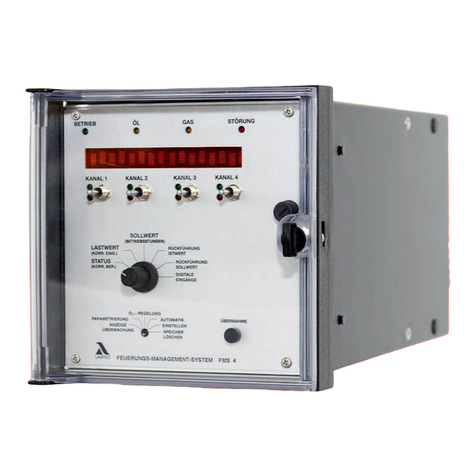
Lamtec
Lamtec FMS 4 quick reference

A to Z Rubber Stamps
A to Z Rubber Stamps RAPIDPRINT A Series manual

Central Machinery
Central Machinery 5907 Owner's manual & safety instructions
