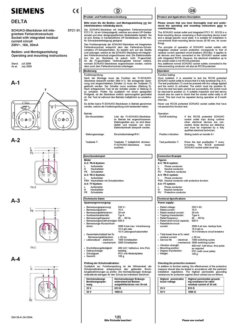
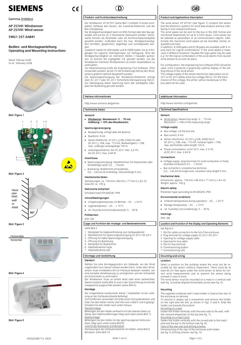
manuals.online logo
Brands
  1. Home
  2. •
  3. Brands
  4. •
  5. Siemens
  6. •
  7. Accessories
  8. •
  9. Siemens AP261 User manual

Siemens AP261 User manual

instabus rf
Technical Product Information
January 2005
Binary Input wave AP 261 5WG3 261-3AB11
Siemens AG wave AP 261, 4 pages Technical Manual
Automation and Drives Group
Electrical Installation Technology Siemens AG 2005 Update: http://www.siemens.de/gamma
P.O. Box 10 09 53, D-93009 Regensburg Subject to change without prior notice
2.20.3.2/1
Product and Applications Description
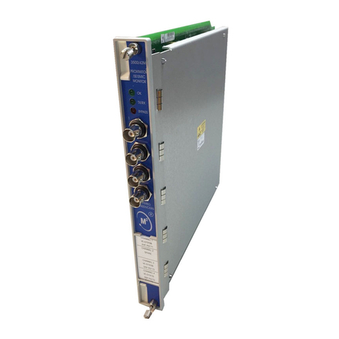
The binary input wave AP 261 (Diagram A) is a surface-
mounted radio-controlled sensor. Besides the integrated
reed contact it is also possible to connect and monitor an
external contact. The difference between the binary input
wave AP 261 and the door/window contact wave AP 260
is that the binary input transmits ON/OFF switching
commands instead of Door/Window Open/Closed mes-
sages as the door/window contact does. With these
switching commands all switchable radio-controlled ac-
tuators can be controlled such as switch inserts sys or
universal dimmer inserts sys in connection with push
buttons wave UP 210 as well as the transmitter actuator
230V wave UP 560. Thus the opening and closing of a
door can be used e.g. for lighting control.
The binary input sends a switching command OFF when
the internal or external contact becomes closed and a
switching command ON when the contacts become
opened. The internal contact is closed if the distance be-
tween the sensor (A3) and the magnet (A4) is < 10 mm.
Diagram A
The binary input is supplied with power from a lithium
battery (1/2 AA 3.6V) which is provided with the device.
This battery is rated so that it is only necessary to replace
it approx. every 5 years, even with up to 50 changes in
the switching state per day. If the battery has to be re-
placed, this is indicated by the LED (A1) flashing every
10 s. The battery must then be replaced within a month.
The commissioning of the binary input is carried out
without any additional tools via a push button located at
the front of the device (A2).
The binary input wave AP 261 has two different opera-
tion modes:
Normal function
• Transmitting switching commands via radio
• Reporting the battery status every 24 hours
Special function
• Establishing connections with other radio- controlled
components
• Deleting connections with other radio-controlled compo-
nents
Operation
Once the binary input wave has been installed and
commissioned, a switching telegram is sent each time
the integrated contact or a connected external contact is
opened and closed. Each switching telegram is sent
twice with an interval of one second in order to increase
the reliability of the transmission. To indicate the sending
of a radio telegram, the LED (A1) lights up briefly.
Technical Specifications
Frequency band
868 MHz (transmission is not susceptible to interference;
frequency band reserved for system and security appli-
cations)
Range of radio control
approx. 100 m (In free field applications)
Power supply
lithium battery 1/2 AA 3.6V (e.g. Sonnenschein, type SL-
750), battery operation time approx. 5 years
Connections
4 plug-in terminals for wire ranges between 0.14 and 0.5
mm2, single-core or finely-stranded; for setting whether
an external contact is to be connected as well as for the
connection of an external contact.
Mechanical specifications
• Housing: plastic
• Dimensions (L x W x H): sensor: 87x36x27 mm
magnet: 40x10x10 mm
• Weight of sensor: approx. 65g (with battery)
• Fire load: approx. 800kJ
• Mounting: fixed with adhesive or screws
A
1
A
2
A
4
A
3
instabus rf
Technical Product Information
January 2005
Binary Input wave AP 261 5WG3 261-3AB11
Technical Manual wave AP 261, 4 pages Siemens AG
Automation and Drives Group
Update: http://www.siemens.de/gamma Siemens AG 2005 Electrical Installation Technology
Subject to change without prior notice P.O. Box 10 09 53, D-93009 Regensburg
2.20.3.2/2
Electrical safety
• Pollution degree (according to IEC 60664-1): 2
• Protection (according to EN 60529): IP 20
• Overvoltage category (according to IEC 60664-1): III
• Device complies with EN 60669-2-1 and IEC 60664-1
Electromagnetic compatibility
complies withEN 301489, EN 300220
Environmental specifications
• Climatic conditions: EN 50090-2-2
• Ambient operating temperature: - 5 ... + 45°C
• Storage temperature: - 25 ... + 70°C
• Relative humidity (non-condensing): 5% to 93%
Certification
complies with - standard
- radio frequency rf
- easy mode push button EP
CE norm
complies with the EMC regulations (residential build-
ings),
low voltage regulations and R&TTE regulations:
The CE declaration can be inspected at:
SIEMENS AG
Siemensstraße 10
93055 Regensburg
Installation Instructions
Caution:
• The device may be used for interior installations and in
dry rooms only.
• The device may not be opened for warranty reasons.
• Occasionally the transmission range may be influ-
enced by structural conditions (e.g. reinforced con-
crete) or electric / electronic sources of interference.
• Aminimum distance of 1 m must be maintained be-
tween the binary input wave and the relevant receivers.
• Although the radio transmission is carried out in the
safe 868 MHz range, disruptions to the radio transmis-
sion cannot be excluded.
• This product is not suitable for security applications in
professional alarm systems.
Mounting
It is advisable to attach the radio-controlled sensor to the
fixed door/window frame and to attach the magnet to the
movable door or window. The mounting plate (B2) of the
binary input (B1) as well as the magnet (B3) can be fixed
using the supplied adhesive strips or with screws if nec-
essary. When using the adhesive strips the ground must
be clean and non-greasy. It should be ensured that the
SIEMENS markings on the mounting plate and magnet
lie on top of each other as much as possible (Diagram B)
and that the distance (gap) between the mounting plate
and the magnet is at least 3 mm but does not exceed
10 mm. With the magnet at this distance from the binary
input, the internal reed contact is closed.
Diagram B
Before clipping the radio-controlled sensor onto the
mounting plate, the insulating strip (C4) that is inserted in
the battery compartment (C1) on the back of the sensor
must be removed and if necessary an external contact
should be connected.
Diagram C
B1
B2
B3
min. 3mm
max. 10mm
C2
C3
C1
C4
C5
instabus rf
Technical Product Information
January 2005
Binary Input wave AP 261 5WG3 261-3AB11
Siemens AG wave AP 261, 4 pages Technical Manual
Automation and Drives Group
Electrical Installation Technology Siemens AG 2005 Update: http://www.siemens.de/gamma
P.O. Box 10 09 53, D-93009 Regensburg Subject to change without prior notice
2.20.3.2/3
First the radio-controlled sensor (D1), as shown in Diagram
D, must be placed onto the mounting plate (D2). You
should then slide it in the direction of the arrow until the
clamps (D3) click into place.
Diagram D
Dimension Diagram
Dimensions in mm
27
32
36
87 72
Connection of an External Contact
An external contact can be connected to the binary input
wave via plug-in terminals (C3) on the rear of the radio-
controlled sensor. The external contact can be con-
nected electrically in series with the reed contact in the
radio-controlled sensor or can be used on its own.
Note: Due to the low voltage and low current levels that
are used for the contact surveillance (to ensure a long
battery life time), only encapsulated contacts as those of
reed relays or measuring relays should be used.
Use internal contact only
Diagram E1 indicates the plug-in terminals of the binary
input in the supplied state. It has been set via the wire
jumper between terminals 3 and 4 that only the internal
contact is used.
Use external contact only
Diagram E2 indicates the terminal assignment when only
an external contact should be used. The internal contact
has been deactivated via the wire jumper between ter-
minals 1 and 2.
Use internal and external contact
Diagram E3 indicates the terminal assignment if the in-
ternal and an external contact should be used together.
The wire jumper is omitted in this case.
Diagram E1 Diagram E2 Diagram E3
Strain relief
The cable can be fixed to the external contact via the
supplied clamping plate (C5). The maximum permitted
diameter of the connecting cable is 5 mm.
Note: The binary input sends a switching command OFF
when the internal contact or an external contact is closed
and an ON switching command when they are opened.
Location and Function of the Display and
Operating Elements
Diagram A
A1 LED for displaying the sending of a radio tele-
gram, the link with other radio-controlled compo-
nents and a low battery
A2 Push button for linking the binary input with other
radio-controlled components
Diagram C
C1 Battery compartment
C2 Battery
C3 Plug-in terminals for setting whether an external
contact should be used as well as for the connec-
tion of an external contact
Commissioning
Note
When commissioning a binary input wave, it must be
linked via “learning telegrams” to the KNX radio-
controlled devices which should process its radio tele-
grams. Only those radio-controlled devices which are
able to process a switching command (ON/OFF) can be
connected to a binary input. These devices are e.g. a
universal dimmer insert sys or a switch insert sys in con-
1 2 3412
3 4 1 2 34
D1
D2
D3
2.
1.
instabus rf
Technical Product Information
January 2005
Binary Input wave AP 261 5WG3 261-3AB11
Technical Manual wave AP 261, 4 pages Siemens AG
Automation and Drives Group
Update: http://www.siemens.de/gamma Siemens AG 2005 Electrical Installation Technology
Subject to change without prior notice P.O. Box 10 09 53, D-93009 Regensburg
2.20.3.2/4
nection with a push button wave, the transmitter actuator
230V wave and the Touch-Manager wave.
Connection via radio
To link (teach in) a binary input wave (F1) to an actuator
such as a universal dimmer insert sys in connection with
a push button wave (F2) or a Touch-Manager wave
(G3), the actuator must first be switched to the special
function “learning mode” (refer to the commissioning in-
structions of the device).
Diagram F
The push button (A2) on the binary input must then be
pressed for approx. 1 s. The LED (A1) flashes for
approx. 3 s if the learning telegrams have been sent.
It can now be tested by opening and closing the internal
contact with the magnet or by operating the external
contact whether the binary input sends a radio telegram
each time (LED A1 lights up briefly) and whether the ra-
dio telegrams have been received and processed cor-
rectly by the devices that are linked via radio.
Deleting a link
If a taught-in device should no longer react to this binary
input, the radio connection should be deleted i.e. re-
taught. When deleting a link, the same process is fol-
lowed as for the connection.
Replacing the Battery
The LED (A1) indicates that the battery needs to be re-
placed by flashing briefly every 10 s. In order to be able
to replace the battery, the radio-controlled sensor must
be removed from its mounting plate. To do so, the lug
(G3) must be pressed down with a tool (e.g. a small
screwdriver (G4)) in the gap between the radio-
controlled sensor (G1) and the mounting plate (G2). You
should then slide the radio-controlled sensor (G1) to the
left over the lug and out of its clamps (G5).
The battery compartment (C1) is located on the under-
side of the radio-controlled sensor. Its housing does not
need to be opened to replace the battery. The correct
polarity should be observed when replacing the battery.
Once the battery has been replaced, the radio-controlled
sensor must be placed onto the mounting plate again, as
shown in Diagram G.
Finally, it should be tested by opening and closing the in-
ternal contact with the magnet or by operating the exter-
nal contact whether the binary input sends a radio tele-
grams each time (LED A1 lights up briefly) and whether
the radio telegrams have been received and processed
correctly by the devices linked via radio. The LED (A1)
should also have stopped flashing at cyclic intervals to
indicate that the battery is low.
Diagram G
General Notes
• The operating instructions should be handed over to
the customer.
• Any faulty devices should be returned to the local
SIEMENS office.
• Should you have any further queries about this prod-
uct, please contact our Technical Support Department:
℡+49 (0) 180 50 50-222
"+49 (0) 180 50 50-223
!adsupport@siemens.com
hwww.siemens.de/automation/support-request
F1
F2
F3
1.
G1
G5
G4
G3 G2
2.
The used battery must be disposed of in
accordance with the applicable regulations.

This manual suits for next models

1

Other Siemens Accessories manuals

Siemens 6DR4004-6NN Series User manual

Siemens

Siemens 6DR4004-6NN Series User manual

Siemens Milltronics TASS User manual

Siemens

Siemens Milltronics TASS User manual

Siemens TA1Q300 User manual

Siemens

Siemens TA1Q300 User manual

Siemens milltronics WEIGHFEEDER 1200 Series User manual

Siemens

Siemens milltronics WEIGHFEEDER 1200 Series User manual

Siemens QMX3.P35H Series User manual

Siemens

Siemens QMX3.P35H Series User manual

Siemens QFM2100 Service manual

Siemens

Siemens QFM2100 Service manual

Siemens Milltronics RBSS User manual

Siemens

Siemens Milltronics RBSS User manual

Siemens RUGGEDCOM WIN7025 User manual

Siemens

Siemens RUGGEDCOM WIN7025 User manual

Siemens Symaro QAA2890/WI User manual

Siemens

Siemens Symaro QAA2890/WI User manual

Siemens SITRANS LR 400 User manual

Siemens

Siemens SITRANS LR 400 User manual

Siemens SITRANS AS100 User manual

Siemens

Siemens SITRANS AS100 User manual

Siemens SIMATIC RF300 User guide

Siemens

Siemens SIMATIC RF300 User guide

Siemens RUGGEDCOM WIN7018 User manual

Siemens

Siemens RUGGEDCOM WIN7018 User manual

Siemens SITRANS LG240 User manual

Siemens

Siemens SITRANS LG240 User manual

Siemens QFA3100 Service manual

Siemens

Siemens QFA3100 Service manual

Siemens jpQO User manual

Siemens

Siemens jpQO User manual

Siemens Brodersen MC55 Setup guide

Siemens

Siemens Brodersen MC55 Setup guide

Siemens SITRANS FSS200 User manual

Siemens

Siemens SITRANS FSS200 User manual

Siemens QNA2 D Series Guide

Siemens

Siemens QNA2 D Series Guide

Siemens SITRANS LG270 User manual

Siemens

Siemens SITRANS LG270 User manual

Siemens SITRANS FC430 Quick start guide

Siemens

Siemens SITRANS FC430 Quick start guide

Siemens SITRANS F User manual

Siemens

Siemens SITRANS F User manual

Siemens QVM62.1 Owner's manual

Siemens

Siemens QVM62.1 Owner's manual

Siemens QPM11 Series User manual

Siemens

Siemens QPM11 Series User manual

Popular Accessories manuals by other brands

Summit Solo Deluxe manual

Summit

Summit Solo Deluxe manual

SEVERIN EM 3965 Dimensions

SEVERIN

SEVERIN EM 3965 Dimensions

Panlux H-228/M user manual

Panlux

Panlux H-228/M user manual

turck FCS-G1/4A4-NAEX/D100 manual

turck

turck FCS-G1/4A4-NAEX/D100 manual

Kaiser Baas Pocket Charge 6K quick start

Kaiser Baas

Kaiser Baas Pocket Charge 6K quick start

fontastic Loru user manual

fontastic

fontastic Loru user manual

esera automation 20002 user guide

esera automation

esera automation 20002 user guide

Aromasound LILYCHERRY operating instructions

Aromasound

Aromasound LILYCHERRY operating instructions

Evolveo WiFi WATER manual

Evolveo

Evolveo WiFi WATER manual

Elko Inels RFDSC-71 manual

Elko

Elko Inels RFDSC-71 manual

Omron E3X-NL - datasheet

Omron

Omron E3X-NL - datasheet

Hytronik HC018V user manual

Hytronik

Hytronik HC018V user manual

WAC Lighting MS-120 Installation instruction

WAC Lighting

WAC Lighting MS-120 Installation instruction

EDLUND KSR-5000 Operation instructions

EDLUND

EDLUND KSR-5000 Operation instructions

X4-Life Video Ski Goggles HD1 user manual

X4-Life

X4-Life Video Ski Goggles HD1 user manual

Hornbach 6145082 Installation and user manual

Hornbach

Hornbach 6145082 Installation and user manual

schmersal CSS 30S operating instructions

schmersal

schmersal CSS 30S operating instructions

MERCATOR ikuu SDC8G quick start guide

MERCATOR

MERCATOR ikuu SDC8G quick start guide

manuals.online logo
manuals.online logoBrands
  • About & Mission
  • Contact us
  • Privacy Policy
  • Terms and Conditions

Copyright 2025 Manuals.Online. All Rights Reserved.