Siemens S2588 User manual

Information and Communication Products
Mobile Phones
Service Manual S25 / S2588 V 1.1 ICP CD ST
R. Fleuren
Sm_S25_lvl2_v11 Page 1of 35 02/00
Service Manual
for
S25 / S2588
V 1.1

Information and Communication Products
Mobile Phones
Service Manual S25 / S2588 V 1.1 ICP CD ST
R. Fleuren
Sm_S25_lvl2_v11 Page 2of 35 02/00
1 Introduction
The S25 is the first dualband handset (GSM-900 and GSM-1800) in the S-class.
The S2588 is a special version for the asian market . It carries a different software which supports
presentation of chinese character set in the phones display.
This manual is intended to help you carry out repairs up to level 2 on the mobile telephones -S25 and
S2588.
For information on level 2.5 repairs or on the testequipment, please refer to the available
documentation.
The repairs for S25 and S2588 are identical unless otherwise noted, and therefore in the text only S25
is mentioned.
Attention:
It must be noted that all repairs have to be carried out in an environment set up according to the ESD
(Electrostatic Discharge Sensitive Devices) regulations defined in international standards.
If you have any questions or comments regarding repair procedures or this service manual, please do
not hesitate to contact the technical support team in Kamp-Lintfort, Germany:
!: +49 2842 95 4666
": +49 2842 95 4302

Information and Communication Products
Mobile Phones
Service Manual S25 / S2588 V 1.0 ICP CD ST
R. Fleuren
Sm_S25_lvl2_v11 Page 3of 35 06/99
2 Table of Contents
1 INTRODUCTION..........................................................................................................................................2
2 TABLE OF CONTENTS...............................................................................................................................3
2 TECHNICAL DATA.....................................................................................................................................5
3 GENERAL INFORMATION .......................................................................................................................6
4 MECHANICAL CONCEPT.........................................................................................................................6
4.1 MECHANICAL DRAWING............................................................................................................................8
4.2 NECESSARY TOOLS ...................................................................................................................................9
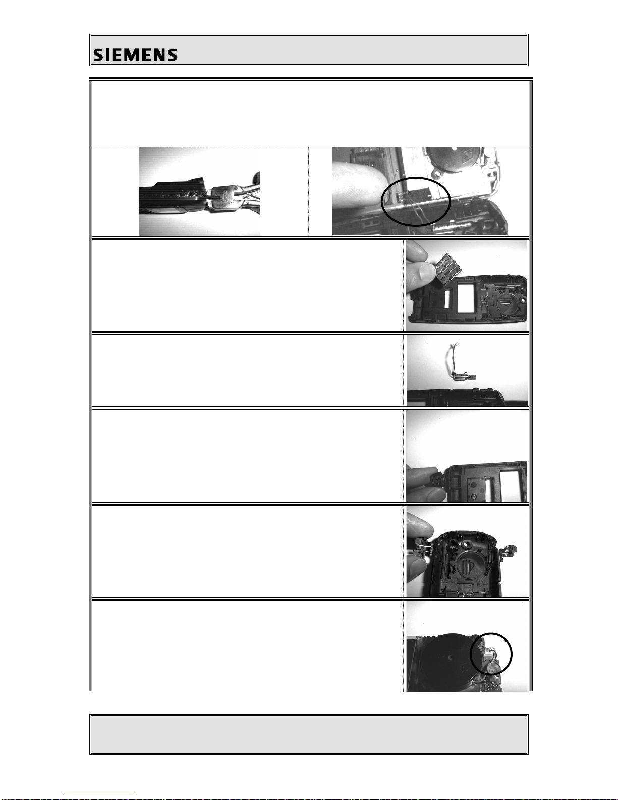
4.3 DISASSEMBLING THE S25..........................................................................................................................9
4.4 ASSEMBLING THE S25.............................................................................................................................13
4.5 HANDSET DATECODES............................................................................................................................17
5 HARDWARE CONCEPT...........................................................................................................................18
5.1 BLOCK DIAGRAM....................................................................................................................................18
5.2 HARDWARE DESCRIPTION.......................................................................................................................19
5.3 POWER SUPPLY CONCEPT .......................................................................................................................21
5.4 OVERVOLTAGE CONDITIONS...................................................................................................................21
6 SOFTWARE PROGRAMMING................................................................................................................22
6.1 HARDWARE OVERVIEW FOR SOFTWARE UPDATE....................................................................................23
6.2 DESCRIPTION OF SOFTWARE BOOTING.....................................................................................................23
6.2 LANGUAGE GROUPS................................................................................................................................24
6.3 CUSTOMER SPECIFIC INITIALISATIONS....................................................................................................24
7 BATTERY ....................................................................................................................................................25
7.1 SPECIFICATION........................................................................................................................................25
7.2 CHARGING ..............................................................................................................................................25
7.3 SCHEMATIC OF THE BATTERY..................................................................................................................26
7.3 SHORT CIRCUIT PROTECTION..................................................................................................................27
7.4 BATTERY DATECODES ............................................................................................................................27
7.5 DEEP DISCHARGE....................................................................................................................................28
8 UNBLOCKING............................................................................................................................................29
8.1 SIEMENS HOTLINE ..................................................................................................................................29
8.2 INTERNET SOLUTION ...............................................................................................................................29
9 ACCESSORIES............................................................................................................................................30
9.1 RAPID CHARGER (INCLUDED IN PACKAGE) .............................................................................................30
9.2 BATTERY (INCLUDED IN PACKAGE).........................................................................................................30
9.3 EXTENDED BATTERY ..............................................................................................................................31
9.4 RAPID CHARGER.....................................................................................................................................31
9.5 TRAVEL CHARGER..................................................................................................................................31
9.6 DESK TOP CHARGER...............................................................................................................................31
9.7 CAR CHARGER........................................................................................................................................32
9.8 ANTENNA CRADLE ..................................................................................................................................32
9.9 CAR KIT PORTABLE ................................................................................................................................32
9.10 CAR KIT COMFORT ................................................................................................................................32
9.11 CAR HANDSET ........................................................................................................................................33
9.12 CAR KIT PROFESSIONAL VOICE ..............................................................................................................33
9.13 PHONE ADAPTER PROFESSIONAL............................................................................................................33

Information and Communication Products
Mobile Phones
Service Manual S25 / S2588 V 1.0 ICP CD ST
R. Fleuren
Sm_S25_lvl2_v11 Page 4of 35 06/99
9.14 ADAPTER KIT PROFESSIONAL .................................................................................................................33
9.15 DATA CABLE PROFESSIONAL..................................................................................................................34
9.16 SOFT DATA LINK PRO.............................................................................................................................34
9.17 DATA CABLE ..........................................................................................................................................34
9.18 HEADSET.................................................................................................................................................34
9.19 BELT CLIP...............................................................................................................................................35
9.20 LEATHER CASE .......................................................................................................................................35

Information and Communication Products
Mobile Phones
Service Manual S25 / S2588 V 1.0 ICP CD ST
R. Fleuren
Sm_S25_lvl2_v11 Page 5of 35 06/99
2 Technical Data
Length: 117 mm (w/o antenna)
137 mm (with antenna)
Width: 47 mm
Thickness: 23,5 mm
Volume: 110 cm³ (approx.)
Weight: 125 g (approx.)
Standards: GSM Phase 2
Performance: GSM 900, Class 4 (2 Watt)
GSM 1800, Class 1 (1 Watt)
Battery: Li-Ion, 3.6V, 650mAh
Standby time: Up to 200 hours (Standard battery)
Up to 400 hours (Extended battery)
Talk time: Up to 5 hours (Standard battery)
Up to 10 hours (Extended battery)
Display: Graphical colour display, 97*54 pixels
SIM Card Type: Plug-In, 3V and 5V types supported
Antenna: Non-retractable, Lambda/2 helix type, Plug-In
Accessories: a) Standard:
Rapid Charger, Standard Battery (3.6V, 650mAh)
b) Optional:
Extended Battery, Travel Charger, Desk Top Charger,
Car Charger, Antenna Cradle, Car Kit Portable, Car Kit Comfort,
Car Handset, Car Kit Professional Voice,
DataCable,Phone Adapter Professional, Adapter Kit Professional,
Data Cable Professional, Soft Data Link Pro, Headset, Belt Clip,
Leather Case

Information and Communication Products
Mobile Phones
Service Manual S25 / S2588 V 1.0 ICP CD ST
R. Fleuren
Sm_S25_lvl2_v11 Page 6of 35 06/99
3 General Information
With the S25/S2588 is the first dual band, E-GSM and triple rate telephone of the
S-class of Siemens mobiles. The target consumer group of this class is the High-End
customer who requires an attractive telephone capable of high operating times and
equipped with an advanced set of features.
This telephone is a so called Dual band telephone, meaning it is capable of
operating in GSM 900 networks as well as in GSM 1800 ones.
The S2588 is a special version of S25, which is designed for the asian market. The
only difference between S25 and S2588 except the name is the different software
inside.
The software of S2588 supports presentation of
chinese characters on the display, the S25 software
does not.
The mobile offers professional features to the customer, of which some are available
for the very first time in a Siemens phone. Specific features are not available in every
model of S25. The decision is taken by the relevant customer (network operator,
service provider), and the phones he buys are programmed by Siemens in an
appropriate way. This has also an effect on the repair process. Please refer to the
chapter „Customer Specific Initialisations“ in this manual.
4 Mechanical Concept
Note: All part numbers refer to mechanical drawing in section 4.1!
The mechanical concept of the S25 differs in various points from the one of the other Siemens
mobile telephones.
The first thing you will experience is how the housing is locked. The housing concept is
similar to the one of C25, meaning that in S25 no screws are used to keep the housing closed.
Also inside the telephone no screws are used anymore. To open the housing, which is kept
closed by catches only, the same opening tool as for C25 can be used. For details on
disassembly please refer to the relevant chapter in this manual.
In opposite to C25, in S25 the battery is part of the housing of the phone, so there no separate
battery cover is necessary.
Inside the housing the S25 consists of two separate boards, the MMI module (1010) and the
RF/Control module (1000). The boards are interconnected not by a plug or an interconnector
as known e.g. in S6 phones, but by a flexible cable (1030). This cable not soldered to the

Information and Communication Products
Mobile Phones
Service Manual S25 / S2588 V 1.0 ICP CD ST
R. Fleuren
Sm_S25_lvl2_v11 Page 7of 35 06/99
boards, but plugged into two connectors. Therefore it can be exchanged easily in case of being
damaged.
The ringer (1120) of the phone is mechanically fixed on the RF/Control board by a special
clip (1190) and electrically connected to the board by means of a cable and a plug. In the
same way the vibra alert unit (1160) is connected, so both components can be exchanged
without doing soldering work. In S25 the vibra alert unit is not a part of the battery but of the
phone itself.
Dust protection frame (1200), cover for IR-interface (1280) and loudspeaker (1140) including
spacer (1250) are mounted to th upper housing (1060). The lower housing (1070) carries
antenna (1150), battery contacts (1170), microphone (1130), vibra alert unit (1160) and the
buttons for voice memo (1350) and side keys (1340).
The antenna (1150) is of a plug-in type, as it is used in Siemens mobiles since C10/C11.
Attention:
The antenna of C10, C11, C25 and S25 are of different types. Be carefull not to mix them up.
S25 carries the same type of external connector as it was introduced with C25. This new
„Lumberg“-connector does not feature connecting an external antenna, and therefore there is a
separate connector for external antenna located at the back side of the upper end of the
mobile, close to the internal antenna (1150). This connector contains the mechanical antenna
switch inside. The switch is operated by inserting the appropriate plug e.g. of a car kit
comfort.
To perform measurements on the S25 and for software updates the same adapter cable
between bootadapter and mobile can be used as it was for C25. For further information on the
testequipment please refer to the appropriate documentation or contact the technical support
department.

Information and Communication Products
Mobile Phones
Service Manual S25 / S2588 V 1.0 ICP CD ST
R. Fleuren
Sm_S25_lvl2_v11 Page 8of 35 06/99
4.1 Mechanical drawing
Note:
The numbers shown above are NO ordering numbers.
For ordering please use the partnumbers supplied by your service manager!

Information and Communication Products
Mobile Phones
Service Manual S25 / S2588 V 1.0 ICP CD ST
R. Fleuren
Sm_S25_lvl2_v11 Page 9of 35 06/99
4.2 Necessary tools
For disassembling the S25 the following Case Opener is
mandatory:
Ordering number of Case Opener: F30032-P46-A1
4.3 Disassembling the S25
Attention: ESD regulations have to be followed!
1. First you remove the battery.
2. Now remove the SIM card:
First you open the lock of the card holder by moving it as
shown in the figure beside.
Then you lift the holder and take out the SIM card.
3. Then you pull the antenna out.

Information and Communication Products
Mobile Phones
Service Manual S25 / S2588 V 1.0 ICP CD ST
R. Fleuren
Sm_S25_lvl2_v11 Page 10 of 35 06/99
4. Open the housing with the opening tool and carefully pull the lower housing section off.
Warning!
The silent alarm unit is mounted in the lower housing section. Be careful not to damage
the cable while pulling the lower housing section off. Disconnect the silent alarm plug-in
connector afterwards.
5. Now remove the battery contacts from the lower housing
section.
6. Remove the silent alarm from the lower housing section.
Warning!
When disassembling, do not pull the silent alarm cable.
7. Remove the microphone from the lower housing section.
8. Remove the buttons for volume and voice memo from the
lower housing section.
9. After that you disconnect the ringer plug-in connector.

Information and Communication Products
Mobile Phones
Service Manual S25 / S2588 V 1.0 ICP CD ST
R. Fleuren
Sm_S25_lvl2_v11 Page 11 of 35 06/99
10. You then remove the ringer from the lower RF-screen.
11. Remove the clip from the lower RF-screen.
12. Remove the operating module and the radio and control
module simultaneously from the upper housing section.
Warning!
The two modules are connected by means of a flexible cable.
Be careful not to damage it during handling.
13. Then carefully remove the retaining clips of the plug-in connector on the operating
module and pull the connector cable out.
14. If necessary, also remove the retaining clip of the connector
on the radio and control module and pull the flexible cable
out.

Information and Communication Products
Mobile Phones
Service Manual S25 / S2588 V 1.0 ICP CD ST
R. Fleuren
Sm_S25_lvl2_v11 Page 12 of 35 06/99
15. Now remove the keypad mat and the dust protection frame
from the upper housing section.
16. Finally, remove the IR interface window and the loudspeaker
from the upper housing section.

Information and Communication Products
Mobile Phones
Service Manual S25 / S2588 V 1.0 ICP CD ST
R. Fleuren
Sm_S25_lvl2_v11 Page 13 of 35 06/99
4.4 Assembling the S25
Attention: ESD regulations have to be followed!
1. First place the IR interface window and the loudspeaker in
the upper housing section.
WARNING!
If there is no spacer on the loudspeaker, please glue one on
beforehand.
2. Now place the dust protection frame in the upper housing
section.
Warning!
The copper side of the dust protection frame must face the
upper housing section. The dust protection frame clip must be
bent so that it is lying on the receiver casing spacer.
3. Place the keypad mat in the upper housing section.
4. If necessary, open the plug-in connector on the radio and control module, insert the
flexible cable and close the plug-in connector again (see figures below).
Warning!
The flexible cable must be inserted parallel in the connector right up to the stopper. The
connector must snap into place at the stopper.

Information and Communication Products
Mobile Phones
Service Manual S25 / S2588 V 1.0 ICP CD ST
R. Fleuren
Sm_S25_lvl2_v11 Page 14 of 35 06/99
5. Place the operating module on the radio and control module, open the connector, and
insert the flexible cable. Then close the connector again. See figures below.
Warning! The flexible cable must be inserted parallel in the connector right up to the
stopper. The connector must snap into place at the stopper.
6. Now place the connected modules simultaneously in the
upper housing section.
7. Place the clip on the lower RF-screen lid. The projection on
the clip must be fitted into the corresponding hole in the
screen lid.
8. Place the ringer on the clip. The retaining projections on the
clip must be fitted exactly into the holes in the ringer.
Warning!
If there is no spacer on the clip, please glue one on
beforehand.
9. Connect the ringer plug-in connector.
Warning!
The cable must be introduced between screen frame and the
RF socket. Otherwise it could be damaged during assembling
the housing of the phone.

Information and Communication Products
Mobile Phones
Service Manual S25 / S2588 V 1.0 ICP CD ST
R. Fleuren
Sm_S25_lvl2_v11 Page 15 of 35 06/99
10. Now you place the keys for the volume and voice memo in
the lower housing section.
11. Now place the microphone, the silent alarm unit and the
battery contacts in the lower housing section.
Warning!
The contacts of the components must not be bent, damaged
or dirty.
12. Insert the silent alarm cable in the connector on the radio and
control module.
Warning!
The silent alarm cable must not be pinched when the device
is closed.
13. Close the device by putting on the lower housing section.
Warning!
All catches must engage completely.
14. Now push the antenna in.
15. Now you insert the SIM card into the holder, and close the
holder by moving it into the shown direction until it locks up.

Information and Communication Products
Mobile Phones
Service Manual S25 / S2588 V 1.0 ICP CD ST
R. Fleuren
Sm_S25_lvl2_v11 Page 16 of 35 06/99
16. Finally you close the telephone by inserting the battery in the
shown manner.

Information and Communication Products
Mobile Phones
Service Manual S25 / S2588 V 1.0 ICP CD ST
R. Fleuren
Sm_S25_lvl2_v11 Page 17 of 35 06/99
4.5 Handset Datecodes
Siemens is using the industrial standard DIN EN 60062 to indicate the production / service
dates. The code is printed on the IMEI sticker located in the battery compartment.
YY = Datecode
•The first character of the datecode indicates the year of production:
F = 1995
H = 1996
J = 1997
K = 1998
L = 1999
•The second character indicates the month of production:
1-9 = january to september
O = october
N = november
D = december
Example: “L5” means that the set was produced in may of 1999.

Information and Communication Products
Mobile Phones
Service Manual S25 / S2588 V 1.0 ICP CD ST
R. Fleuren
Sm_S25_lvl2_v11 Page 18 of 35 06/99
5 Hardware Concept
5.1 Block Diagram

Information and Communication Products
Mobile Phones
Service Manual S25 / S2588 V 1.0 ICP CD ST
R. Fleuren
Sm_S25_lvl2_v11 Page 19 of 35 06/99
5.2 Hardware Description
The handset consists of the following major integrated circuits:
1) HiGOLD (PMB 2800)
This IC is a combination of microprocessor and signalprocessor.
The microprocessor part of this component is responsible for controlling the keyboard, SIM-
Card, Flash and RAM. Furthermore it controls the power up/power down of the RF module
and sets the amplification of the PA.
The signal processor part of PMB 2800 is responsible for processing the Rx I/Q signals
(filtering, equalizing, speech and channel decoding).
Furthermore it does the speech and channel encoding and the GSMK modulation of the Tx
I/Q signals.
2) GOLD-SX (PMB 2709)
The coprocessor PMB 2709 is used to realize advanced features regarding coding of the
speech signal. These are:
•Halfrate-Encoding
•Halfrate-Decoding
•Enhanced Fullrate Encoding
•Enhanced Fullrate Decoding
•Voice Activity Detection
•Comfort Noise
3) GAIM (PMB 2905)
The GAIM (GAIM = GSM Analog Interfacing Module) provides the interface between the
analogue signals (I/Q, voiceband, PA-control, charging control signals) and its digital
representation.
4) Receiver Circuit (PMB 2411)
This circuit provides the following main functionalities:
•Low Noise Amplifier (LNA) with a fixed amplification of +20dB to amplify the input
RF signal.
•Mixer to mix down the RF signal to the Intermediate Frequency (IF)
•Programmable IF amplifier with a dynamic range of 60dB ( -10dB ... +50dB in steps of
2dB).

Information and Communication Products
Mobile Phones
Service Manual S25 / S2588 V 1.0 ICP CD ST
R. Fleuren
Sm_S25_lvl2_v11 Page 20 of 35 06/99
•Mixer to mix down the IF signal to the baseband, generating and inphase (I) and a
quadrature (Q) signal.
•Offset compensation for the I/Q signals.
5) Transmitter Circuit PMB 2255
This circuit provides the IF synthesizer, the I/Q modulator, prescalers to regulate the RF
synthesizer and a buffer stage to feed the PA.
The antenna switch is mechanical, located in the connector for the external antenna.
This manual suits for next models
1
Table of contents
Other Siemens Cell Phone manuals

Siemens
Siemens A62 Setup guide

Siemens
Siemens S55 User manual

Siemens
Siemens S6 GSM User manual

Siemens
Siemens S65 User manual

Siemens
Siemens Be inspired M55 User manual

Siemens
Siemens M65 User manual

Siemens
Siemens Gigaset 4000i Micro User manual

Siemens
Siemens SXG75 User manual

Siemens
Siemens A70 User manual

Siemens
Siemens C60 User manual

Siemens
Siemens SL45 User manual

Siemens
Siemens AX75 User manual

Siemens
Siemens Gigaset M56 User manual

Siemens
Siemens A65 User manual

Siemens
Siemens S65 User manual

Siemens
Siemens M35 User manual

Siemens
Siemens SK65 User manual

Siemens
Siemens MC60 User manual

Siemens
Siemens CX75 User manual

Siemens
Siemens MC60 User manual