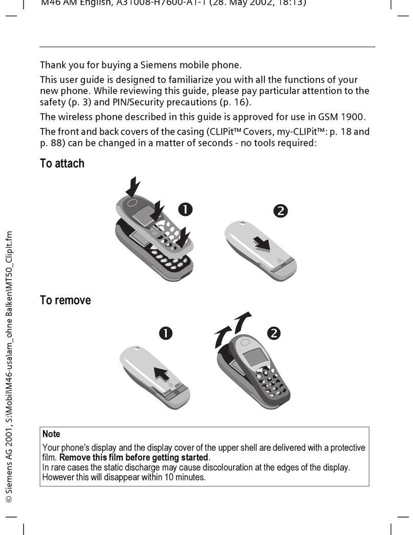
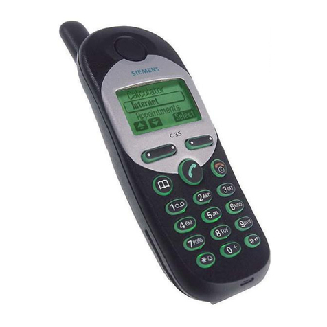
Siemens S35i User manual

V1.0
Local Service Organization Service Manual
S I E M E N S I N F O R M A T I O N A N D C O M M U N I C A T I O N M O B I L E

V1.0 i
Table of Contents

V1.0 1
C H A P T E R 1
Level 2 Service Gui e
Intro uction 1
S35i Series Technical Information 2
Accessories 4
General Information 5
S35i Series Explo e Diagram 7
Mechanical Concept 8
Har ware Concept – Block iagram 9
Har ware Description 10
Power Supply Concept 11
Over voltage Con ition 11
Battery – Charging 12
Short Circuit Protection 12
Charging 13
S35i Mobile Phone Spare Parts Level 2 15
Disassembling/Assembling the S35i 16
Mobile Software Programming 22
Mobile Software Up ating 22
Language Groups 23
Customer Specific Initialization 25
International Mobile Equipment I entity 25
Phone Unblocking 26
Disclaimer 28

V1.0 1
Level 2 Service Gui e
Introduction
The ocument is inten e to help you carry out repair up to Level 2 on the S35i series mobile
phone.
The repair for international version an Asian variants are i entical unless otherwise note ,
therefore the escription herein is confine to S35i only.
The S35i electrical esign is similar to the C35 mobile phone – they use same PCB an
electronics component for majority of the circuit. For testing an the accessories for the S35i
please refer to the C35 service manual.
All repairs have to be carried out in an environment set up
according to ESD regulations defined in international standards.
ESD procedure is available from your Service Manager. Ask for
ASC/T001/ 8
Chapter
Chapter

V1.0 2
S35 i Technical Information
System GSM Phase 2/Phase 2+, Dual Ban
EGSM 900, Class 4(2 Watt)
GSM 1800, Class 1(1 Watt)
Operating Voltage 3.6V
Size(LxWxH) 118 x 46 x 21 mm(without antenna)
Volume 89cm3 inclu ing battery (approx)
Weight 105g inclu ing battery (approx)
Battery(Stan ar ) Li-Ion, 600mAH (Stan ar )
Stan by time1 60-220 hours (stan ar battery)
Talk time1 100-360 minutes (stan ar battery)
Charging Time 2 hours
SIM support Plug in car 1.8 V or 3V
Antenna Integrate
Speech co ec Triple rate Enhance Full Rate
Full Rate
Half Rate
Display 101 x 80 pixel graphical isplay with up to 6 lines
12 x 12 font size for Chinese
Keypa 12 numeric keys(10 numeric, #, *)
4 function keys(Sen , En -ON/OFF, Menu, Phonebook)
2 multifunctional softkeys
Key Soun Click/DTMF/None
Key Lock Activation an Deactivation by #-key or
Automatic.
1 Actual time epen ent on the network.

V1.0 3
Dialing 10 re ial numbers,
Last 10 incoming with ate stamp
Last 10 outgoing calls
Last 10 misse calls with ate stamp
Ringer On/Beep/Off
Up to 42 melo ies an 5 volume settings
Melo y Composer
Volume A justable in 5 levels uring call via softkey
Silent Alert Built-in vibrator
Phone Book Storage epen s on the SIM car capacity
Storage of up to 100 list in the phone (VIP)
SMS Support MT, MO, CB
Pre ictive Text Input, Tegic T9.
Supplementary Call Forwar ing, Call Hol , Call Wait,
Services Multiparty Conference, CLIP, CLIR, AoCC
AoCI, FDN, LND USSD an SAT.
Ciphering A5/1 an A5/2 supporte
PIN control PIN 1 & 2 Co e Control
Phone co e 4 to 8 igit co e
Network function Automatic an manual network selection
Chipset Siemens E – GOLD V 1.2
WAP Browswer1 Version 1.1 (SMS &CSD)
Other Features Clock / Alarm
Alarm List2
Built-in mo em3
Calculator4
Currency Converter
4 Games
Voice memo 20 sec
Voice ialing 20
1 Only for Mo el S35i.
2 Not available in S35 International version.
3 Not available in S35 International version.
4 Not available in S35 International version.

V1.0 4
Tegic T9 Yes
Accessories:
1. Stan ar Battery L36880-N4001-A100
2. Optional Battery L36880-N4001-A101
3. Stan ar Charger L36280-Z4-CXXX (Country Variant)
4. Travel Charger L36880-N4001-A103 (EU) / A104 (UK)
Similar to stan ar charger with an universal input voltage from 90 ~ 240V
4. Desk Top Charger L36880-N4001-A102
5. Belt Clip L36880-N4001-A113
6. Hea set L36880-N4001-A123
7. Antenna Cra le L36880-N4001-A110
8. Car Charger Cable L36880-N4001-A108
9. Car Kit Portable1 L36880-N3015-A117
10. Car Kit Comfort L36880-N4001-A111
11. Car Han set2 L36880-N3015-A123
12. Designer Cases L36880-N4001-A119
13. SoftDataLink 3.0 L36880-N4001-A122
14. Data Cable3 L36880-N3101-A102
15. Car Kit Professional Voice L36880-N4001-A124
16. Data Cable Professional4 L36880-N3101-A112
1 Same as C25(88)
2 Same as C25(88)
3 Same as C25(88)
4 Same as C25(88)

V1.0 5
General Information
Due to ifferent requirements of the markets, the S35i has ifferent variants, which broa ly
classifie un er International version an Asian version. Marketing name for international version
is S35i, whereas Asian version is name 3568i.
The ifferent for ASIAN version is only mobile software.
The 3568i is equippe with a graphic isplay which enable the telephone to isplay CHINESE
characters, either in Tra itional font or Simplifie font, besi e the stan ar English.
Wireless Application Protocol, WAP.
Wireless Application Protocol takes a client-server approach that uses the in-built micro-browser
to make a request, in wireless markup language (WML), for information or service. The request is
passe to a WAP Gateway which then retrieves the information from a Internet server, in HTML
format, an translate it into WML. The requeste information is then sent to from the WAP
Gateway to WAP client (mobile) using the available an most appropriate mobile network bearer
services.
Wireless Protocol Stack.
Wireless Application Environment (WAE)
Wireless Session Protocol (WSP)
Wireless Transaction Protocol (WTP)
Wireless Transport Layer Security (WTLS)
Wireless Datagram Protocol (WDP)
Bearers e.g. Data, SMS, USSD
TABLE 1..1 WAP PROTOCOL STACK
1. Wireless Application Environment
Defines the user interface on the phone. WAE contains the WML,WML script an the
wireless telephony application (WTA).
2. Wireless Session Protocol
Link the WAE to two session services – one connection oriente operating above the WTP
an a connectionless service operating above WDP.
3. Wireless Transaction Protocol
Runs on top of the atagram service an part of the stan ar suite of TCP/IP protocols, to
provi e a simplifie protocol suitable for low ban wi th mobile station.
4. Wireless Transport Layer Security
WTLS incorporates security features that are base upon the establishe Transport layer
Security (TLS) protocol stan ar , that inclu e ata integrity checks, privacy on the WAP
Gateway to client leg an authentication.
V1.0 6
5. Wireless Datagram Protocol
Allows WAP to be bearer in epen ent by a apting the transport layer of the un erlaying
bearer. WDP presents a consistent ata format to the higher layer of the WAP stack.

V1.0 7
S35 Series Mechanical iagram
FIGURE 2.1 S35I MECHANICAL DIAGRAM.
Please take note that the number(s) use here IS NOT the part number,
DO NOT use it in your spare parts purchase or er.
A l w a y s r e f e r t o t h e S E R V I C E P A R T P R I C E L I S T
f o r y o u r s p a r e p a r t o r d e r .

V1.0 8
Mechanical Concept
Note: All numbers refer to mechanical drawing in Figure 2.1.
The mechanical concept of the S35i iffers in various points from the one of the other Siemens
mobile telephones.
The first thing you will experience is how the housing is locke . In S35i no screws are use to
keep the housing close . Also insi e the telephone no screws are use anymore. To open the
housing, which is kept close by catches only, a special opening tool has been efine . Once the
phone is open the catches will be amage an a new housing nee to be use . For details on
disassembly tool please refer to Photo 2.3 in this chapter.
Insi e, the S35i consists of just one boar (1010) which carries isplay mo ule(1170), control
part an RF section of the mobile.
The isplay mo ule (1170) is connecte to the boar by a flexible cable which is inserte into a
plug. In case the isplay is efective electrically or mechanically it can be exchange very easily.
S35i oes have an external connector of a new type. Since S6 a so calle “Molex”-connector
was use , which also offere the possibility to connect an external antenna to it. The new
“Lumberg”-connector which is use in S35i oes not feature such a connection, because the
connector for external antenna is locate at the back si e of the upper en of the mobile, close to
the internal antenna (1130). As a consequence of this there is no nee anymore for a RF cable
mounte to the boar nor for a RF plug on it to connect this cable. This improves RF-properties
of the mobile an lowers pro uction costs.
To be able to o measurements on an software up ate of the telephone, an a apter cable
between Molex an Lumberg connector will be available. See photos in Additional Tools of
Chapter 3.
S35i antenna (1130) is a integral part of the lower case shell (1030). The antenna can only be
change by open up the S35i phone an replace the housing.
The S35i is a dual-band mobile operating on GSM 00 and GSM1800,
the antenna is an integral part of the lower housing.
The keypa (1150), the microphone (1110) an the lou speaker (1120) are mounte into the
upper case shell (1020). Make sure that the microphone an the earphone contact springs are
not irty or amage uring repair process.

V1.0 9
Hardware Concept – Block iagram
FIGURE 2.2 S35 I BLOCK DIAGRAM.

V1.0 10
Hardware escription
The han set consists of the following major integrate circuits:
1) E-GOLD (PMB 2850)
This IC is a combination of microprocessor an signal processor.
The microprocessor part of this component is responsible for controlling the keyboar , SIM-
Car , Flash an RAM. Furthermore it controls the power up/power own of the RF mo ule
an sets the amplification of the PA.
The signal processor part of PMB 2800 is responsible for processing the Rx I/Q signals
(filtering, equalizing, speech an channel eco ing).
Furthermore it oes the speech an channel enco ing an the GSMK mo ulation of the Tx
I/Q signals.
The coprocessor PMB 2805 is use to realize a vance features regar ing co ing of the
speech signal. These are:
• Halfrate-Enco ing
• Halfrate-Deco ing
• Enhance Fullrate Enco ing
• Enhance Fullrate Deco ing
• Voice Activity Detection
• Comfort Noise
3) GAIM (PMB 2906)
The GAIM (GAIM = GSM Analog Interfacing Mo ule) provi es the interface between the
analogue signals (I/Q, voiceban , PA-control, charging control signals) an its igital
representation.
4) Transceiver Circui (Brigh II HD155124F)
This circuit provi es the following main functionalities:
• Low Noise Amplifier (LNA) with a fixe amplification of +20 B to amplify the input RF
signal.
• Mixer to mix own the RF signal to the Interme iate Frequency (IF)
• Programmable IF amplifier with a ynamic range of 60 B ( -10 B ~+50 B in steps of
2 B).
• Mixer to mix own the IF signal to the baseban , generating an inphase (I) an a
qua rature (Q) signal.
• Offset compensation for the I/Q signals.
This circuit provi es the IF synthesizer, the I/Q mo ulator, prescalers to regulate the RF
synthesizer an a buffer stage to fee the PA.
The antenna switch is mechanical, locate in the connector for the external antenna.
Power Supply Concept

V1.0 11
The S35i has two main power inputs:
1. Battery voltage(3.6V) connecte at the battery contact
2. Charging voltage(6.5V) elivere by the ifferent charger type(see Accessory List) via the
Lumberg connector at the bottom of the telephone.
Since the battery voltage is supplying the power supply ASIC, it is always nee e to operate the
phone. You canno swi ch on he handse if he ba ery vol age is no presen .
From the battery voltage, all other supply voltages are erive an controlle by the power
supply ASIC.
The RF power amplifier is irectly connect to the battery, a ba battery with high internal
resistance can cause malfunction of the S35i phone.
The Logic mo ule uses 1.92V, 2.65V & 2.9V generate by voltage regulators insi e the ASIC.
Furthermore, the ASIC generates the supply voltage for the SIM car an the RESET signal for
the logic evices.
The ASIC also checks the presence of the watch og signal from the microprocessor an
provi es the switching on functionality (ON_OFF button or Ignition signal).
Wrong polarity or battery voltage setting that exceed the +6.5V
could damage the phone.
Over-voltage Condition
• Battery voltage
If the supply voltage rises above 6.2V, the phone will switch off an it cannot be switche on
again before the voltage is lower than 6.2V.
If the supply voltage rises above 7V, the phone can be amage .
• Charging Current
The charging current must not rise above 1A or a track fuse in the phone will blow. As a
result charging the battery will no longer by possible.

V1.0 12
Be careful with NON-original SIEMENS accessories or chargers.
Make sure that the charging current is limited to value below 1A.
Battery – Charging
S35i series uses a Lithium Ion 600mAH battery pack as stan ar battery. It also support the
Nickel Metal Hyri e (NiMH) 500mAH battery pack (For C35 phone).
PHOTO 2.3 S35i SERIES INSERTING BATTERY.
For S35i, BATT+ has a voltage level from +3.0V to 5.5V, an a BATT_TEMP contact is use for
etecting abnormal increase in temperature of the battery.
If the temperature is too high or too low, there is a high probability
that the battery is not charged. To enable the charging process again,
battery and phone needs to cools down or warm up. Battery
replacement is not required.
A v o i d s h o r t i n g t h e b a t t e r y t e r m i n a l s .
Short Circuit Protection
For the Nickel Metal Hy ri e battery, a polyswitch in the battery pack protecting the battery from
short circuit an it shoul reset by itself after some time removing the short circuit.
For the Lithium Ion battery, it is short-circuit protecte by an electronics fuse. The fuse will be
activate in case a too high current is rawn. This fuse will no rese automatically.
The resetting of the battery fuse can be one with either of the following proce ures:
1. Insert the battery into the S35i an then connect the rapi charger to the phone. Wait for
approximately 10 secon , then the mobile can be turne on again.
2. Plug the battery separately into the esktop charger. The fuse is reset imme iately or,

V1.0 13
3. Insert the battery into the S35i an put the phone into the esktop charger. Wait for
approximately 10 secon , then the mobile can be switche on.
Charging
The battery can be charge when it is inserte into the phone. The charging process is
completely controlle by the mobile. Charging can be one with any of the following accessory:
1. Rapi charger
2. Travel charger
3. Car charger
4. Desktop charger
PHOTO 2.4 INSERT CHARGER
Photo 2.4 shows the correct way of inserting an removing the charger plug.
eep ischarge Battery
In case of a eeply ischarge battery, the voltage of the battery is too low to operate the
charging circuit an the isplay controller, the phone can not be turne on an the normal
charging process can not be starte . No charging symbol is visible in the isplay.
In this case, charging the battery is ivi e into two ifferent steps, which have to be run
subsequently:
a) Trickle charge for S35i Phone
Trickle charge mo e is automatically starte if the battery voltage is below 3.0V when the
charger is connecte to the mobile. The charging current in Trickle mo e is appr. 10mA.
Trickle charge mo e has to last minimum until the battery voltage has excee e 3.2V,
then the phone will switch on an the charging icon appear. During trickle charge the
charging symbol will not be visible an the telephone can not be turne on. This is
because the battery voltage is too low to operate the telephone.
Ac ion:
Insert battery into han set an connect travel charger to the telephone. If within 4 hours
the battery voltage is high enough again, the charging symbol will come up.
If the battery is ischarge very eeply, the symbol may not come up an the trickle
charge time possibly has to be exten e up to 24 hours.

V1.0 14
b) Normal charge
When the battery voltage is above the a.m. value (e.g. by trickle charge) the mobile will
start the normal charging mo e an show a charging symbol in the isplay. * Always
normal charge a new battery or a eep ischarge battery for more then 12 hours before
first use.
Ac ion:
Connect charger to the telephone (see section on Char in ).
The charging symbol will come up as an in ication that the normal charging process has
been starte by the mobile.

V1.0 15
Mobile Phone S35i Spare Parts Level 2
L36880-A34-A.... see Spare Part List
Battery Cover
L36158-A34-B..
Batterie Li-Ion
L36145-K1310-X127
Lower Case Shell
L36158-A34-B20
Vibra-Alert Unit
L36453-Z5-C77
Battery Contact
Spring
L36334-Z97-C113
SIM Car Rea er
with
Car Hol er
L36334-Z97-C111
SIM-Car Hol er
L36334-Z97-C112
Microphone
L36254-Z6-C82
Button Wipp Voice
Memo
L36158-A34-C192
Button Voice Memo
L36158-A34-C191
Cover IRDA-Interface
L36158-A34-C140
Button Wipp Volume
L36158—A34-C182
Button Volume
L36158-A34-C181
RF Control Boar
L36880-Q4100-B206
Buzzer Sealing
L36158-A33-C260
Display mo ule
L36851-Z1508-A50
Cushion
L36158-A34-C103
Earphone
L36212-Z3-C34
Upper Case Shell
L36158-A34-A...
Keypa
L36158-A34-B..

V1.0 16
isassemble the S35i
A case opener is nee e to isengage the latch of the S35i casing.
PHOTO 2.5 C35/S35i CASE OPENER
The part number for this mandatory tool is F30032-P46-A1
Refer to ANNEX B of Chapter 3 for Service Equipment List.
STEP 1 & 2:
Remove the battery cover then the battery as shown in PHOTO 2.6 . Open the housing with the
opening tool an carefully pull the lower housing section off as illustrate in PHOTO 2.7 .
PHOTO 2.6 DISASSEMBLE S35i – STEP 1 PHOTO 2.7 DISASSEMBLE S35i – STEP 2
STEP 3:

V1.0 17
Use the Case Opener carefully isengage the catches of the Lower housing an Upper
housing to separate the housing an the Control Boar Assembly as in PHOTO 2.8
PHOTO 2.8 DISASSEMBLE S35i – STEP 3
isassemble/Assemble of the Lower Housing Assembly
STEP 1:
Open the housing with the opening tool an carefully pull the lower housing section off as
illustrate in PHOTO 2.9
PHOTO 2.9 Lower Housing Assy – STEP 1 PHOTO 2.10 Disassembly Lower Housing – STEP 2
STEP 2:
Remove in sequence by han the SIM Car Hol er, SIM Car Rea er, Battery Contact Spring,
Vibra-Alert Unit, left & right si e button an the Infrare Cover as illustrate in PHOTO 2.10
For the assembly of the Lower Housing just reverse the sequence for the isassembly.
is-assemble/Assemble the Control Board Assembly
STEP 1:
Other manuals for S35i
2
Table of contents
Other Siemens Cell Phone manuals

Siemens
Siemens CX75 User manual

Siemens
Siemens M35i User manual

Siemens
Siemens CL75 Setup guide

Siemens
Siemens C70 User manual

Siemens
Siemens Gigaset 4010 User manual

Siemens
Siemens SL65 Setup guide

Siemens
Siemens C65 User manual

Siemens
Siemens C75 User manual

Siemens
Siemens HiPath C10 User manual

Siemens
Siemens CX70 User manual

Siemens
Siemens AX75 User manual

Siemens
Siemens ST55 User manual

Siemens
Siemens Mobile CF62T User manual

Siemens
Siemens C25 User manual

Siemens
Siemens SL10 Operator's manual

Siemens
Siemens C30 User manual

Siemens
Siemens AL21A User manual

Siemens
Siemens C81 User manual

Siemens
Siemens S55 User manual

Siemens
Siemens PEGASUS-DTC AX72 User manual