Siemens CX75 User manual

Local Service Organization Service Manual
BE INSPIRED
C
C
CX
X
X7
7
75
5
5
V 1.0
Version Date Department Notes to change
R 1.0 06.06.2005 COM D CCQ APAC New Document
Our innovation shapes the future

CX75 Level 2 Service Manual
Copyright © Siemens Pte Ltd. Siemens Technical Support Centre
All Rights Reserved
COM D CCQ APAC SLI Page 2 of 42 Internal Use Only
Table of Contents
1 GPRS (GENERAL PACKET RADIO SERVICE)……………………..….3
2 K JAVA APPLICATION……………………………………………………………….4
3 KEY FEATURES……………………………………………………………………….5
4 COMPARISON WITH PERVIOUS PRODUCT...……………………………………7
5 ACCESSORIES……………………………………………………………………......8
6 UNIT DESCRIPTION CX75..………..……………………………………………….10
7 DISASSEMBLY OF CX75......……………………………………………………….12
8 REASSEMBLY OF CX75..…..………………………………………………………19
9 ASSEMBLING AND DISASSEMBLING OF CAMERA MODULE………………21
10 MOBILE SOFTWARE PROGRAMMING…………………………………………..23
11 SIEMENS SERVICE EQUIPMENT USER MANUAL……………………………..26
12 JPICS INTERNET.……………………………………………………………………27
13 INTERNATIONAL MOBILE EQUIPMENT IDENTITY, IMEI…….………………..33
14 GENERAL TESTING INFORMATION……………………………….……………..34
Annex 1……………………………………………………………………………….……….39
Annex 2…………………………………………………………………………….………….40

CX75 Level 2 Service Manual
Copyright © Siemens Pte Ltd. Siemens Technical Support Centre
All Rights Reserved
COM D CCQ APAC SLI Page 3 of 42 Internal Use Only
1 GPRS (General Packet Radio Service)
GPRS is a new non-voice value added services that allows information to be sent
and received across a GSM mobile telephone network. It supplements today’s Circuit
Switched Data (CSD) and Short Message Services (SMS). GPRS involves overlaying
a packet based air interface on the existing circuit switched GSM network. This gives
the option to use a packet-based data service. The information is split into separated
but related “packets” before being transmitted and reassembled at the receiving end.
Theoretically, maximum speeds of up to 171.2 kilobits per second (kbps) are
achievable with GPRS using all eight timeslots at the same time. This is about 3
times as fast as the data transmission speed possible over today’s fixed
telecommunications networks and 10 times as fast as current Circuit Switched Data
services on GSM networks.
Example: Cell with 1 Frequency channel:
1 physical channel for signaling, 4 physical channels for Circuit switched and 3 physical
channels for Packet switched.

CX75 Level 2 Service Manual
Copyright © Siemens Pte Ltd. Siemens Technical Support Centre
All Rights Reserved
COM D CCQ APAC SLI Page 4 of 42 Internal Use Only
2 K-Java Application
Java-based game system
Java Application Manager
(JAM)
Application launcher and
download manager.
Supports HTTP-based OTA
download of applications over
GPRS and CSD.
yes
RAM for Java applications Available RAM for Java
applications (i.e. Program code
and data) during application
runtime:
Minimum 100 Kbytes (Has to be
taken as working assumption
for application development).
Goal: 145 Kbytes as SL45i (not
committed)
yes
MIDP 1.0, CLDC 1.0 As SL45i, including
performance optimizations from
SL45i-Infusio.
yes
‘OEM extensions’ Proprietary API extension as
SL45i. Including ‘Siemens
Game API’
yes
HTTP API over GPRS Sl45i: only CSD yes

CX75 Level 2 Service Manual
Copyright © Siemens Pte Ltd. Siemens Technical Support Centre
All Rights Reserved
COM D CCQ APAC SLI Page 5 of 42 Internal Use Only
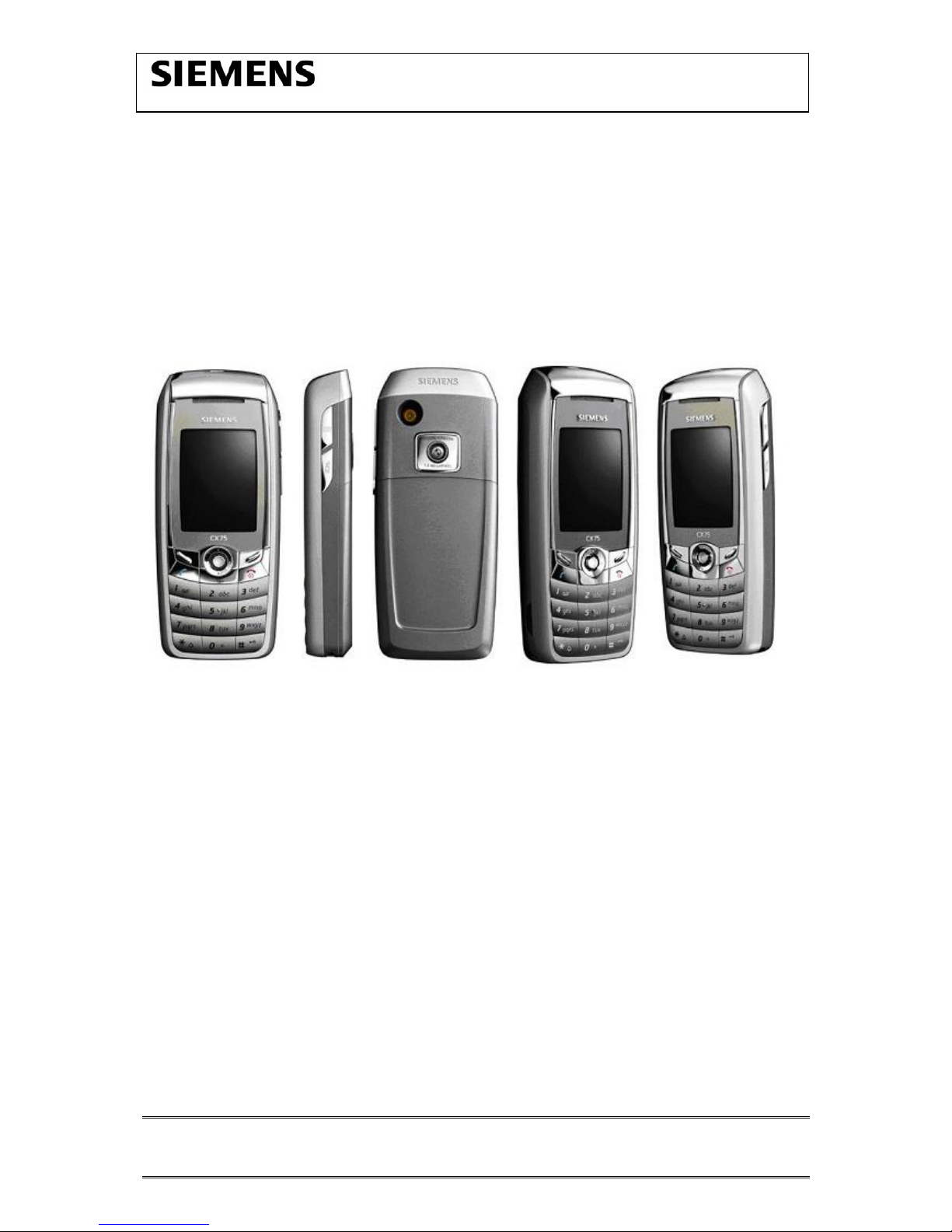
3 Key Features
Bands • Triple Band E-GSM 900 / GSM 1800 / GSM 1900
• GPRS Multi Class 10
Battery • Li-Ion Battery Pack
• Nominal Voltage : 3.7V
• Nominal Capacity : 780 mAh
• GSM Capacity : 750 mAh
• Power Input : 2.0A (0.6 ms) / 0.25A (4 ms)
• Cut-off Threshold : 3.2V
Stand-by Time ≥Approx. 250 h (Best Case)
Talk Time ≥5 hrs (Best Case)
SIM Card
• Small (”Plug In”) 1.8 or 3V SIM card (Phase II)
• To insert the SIM card, the battery pack must be
removed.
Speech Codec
• Triple Rate (HR/FR/EFR) and Adaptive Multi Rate are
available as standard
Temperature
Range
• -100C to +550C (Normal operation)
• -200C to +650C (External Power Source)
• -400C to +850C (Storage capability)
Display • Type: Full Graphic
• Resolution: 132 x 176 Pixel
• Color depth: 262K
• Technology: TFT
• Active area / mm: 27.7 x 37.0
• Illumination: White LED (6 LEDs integrated)
• Frame rate: maximum 15 frames/seconds
• Pixel size per mm: 0.21mm x 0.21mm ( 1 pixel consist
of 3 sub pixels in red, green and blue)
Keypad •Plating function key + IMF number key
• 12-key-block (0-9, #, *)
• two function keys (SEND, END)
• ON/OFF key combined with the END key; the symbol (I
inside O) is used as a symbol for ON/OFF.
• 5 way-joystick with design-cap (soft material), phonebook
symbol required on navikey (Siemens standard)
• 2 soft-keys for different SW-enabled functions
• 1 dedicated hardkey (provider key), target to only have a
specific hardkey only for Vodafone and TMO
• white as illumination colour
• tactile finder on key “5“
• 6 white LEDs for keypad
Side keys • one for Pat (Push and Talk) control, one for camera activation

CX75 Level 2 Service Manual
Copyright © Siemens Pte Ltd. Siemens Technical Support Centre
All Rights Reserved
COM D CCQ APAC SLI Page 6 of 42 Internal Use Only
Acoustics
• Three-in-one-earpiece for handset, handsfree and ringing
tones
• uni-directional microphone
• Loud signal emitter (soundringer) (>100dB(A) SPL @5cm,
'Hongkong-Spec.') only for rectangular sound signals (NOT
POSSIBLE for all Soundringer melodies)
• Polyphonic ringer tones (parallel to GPRS: 16 voices; all
other Use Cases: 40 voices)
• Hands free mode
• different selectable volume levels for handsfree, handset
and ringer mode (for the amount see SW product
description)
Memory • Approx 14MB, Slot RS-MMC, Bundled with 32MB card
Connectivity • USB
• Bluetooth®
• Infrared
Ring tones • Polyphonic 40 voices
• AAC& AAC+ Melodies and MP3
Multimedia • Video recording / encoding
• AAC, AAC+ and MP3 music support
Camera • Integrated 1.3 Mega pixel (attachable Flash accessory)

CX75 Level 2 Service Manual
Copyright © Siemens Pte Ltd. Siemens Technical Support Centre
All Rights Reserved
COM D CCQ APAC SLI Page 7 of 42 Internal Use Only
4 Comparison with Previous Product
Feature S65 CX75 Delta
Supported Systems Triple Band
EGSM 900/GSM1800/
GSM1900 (EMEA,
APAC)
Triple Band
EGSM 900/GSM1800/
GSM1900 (EMEA,
APAC)
No GSM 850
Stand-by Time ≥250h
(approx. 3mA quiescent
current)
≥250h
(approx. 3mA quiescent
current)
Talk Time ≥5 h
(approx. 150mA
average current for
lowest TX-power level)
≥5 h
(approx. 150mA
average current for
lowest TX-power level)
Battery Technology
Battery Capacity
Li-Ion Battery Pack
NOMINAL CAP.: 780
MAH
Li-Ion Battery Pack
NOMINAL CAP.: 780
MAH
Weight Approx. 102 g approx. 102 g
Volume approx. 90.3 cm3
Length 108.9mm 111.7 mm
Width 48 mm 48 mm
Thickness 20.5 mm 19.5 mm
SIM Plug-In 1.8V/3V Plug-In 1.8V/3V
Antenna Integrated Integrated
Antenna Performance
in comparison
~28 dBm @ 900 MHz
~24,5 dBm @ 1800 MHz
~23,5 dBm @ 1900 MHz
(2,7-Band-Antenna)
~27 dBm @ 900 MHz
~24 dBm @ 1800 MHz
~23,5 dBm @ 1900 MHz
(2,7-Band-Antenna)
-1db @ 900 MHz
-0,5db @ 1800 MHz
+/-0db @ 1900 MHz
Half Rate Yes Yes
Enhanced Full Rate Yes Yes
AMR Yes Yes
Fax/Data Yes Yes
GPRS Class 10 Class 10
Keypad Illumination White LED White LED
DISPLAY /
DISPLAY
ILLUMINATION
TFT/TFD
132 x 176 Pixel
65k colour
TFT
132 x 176 Pixel
262k colour
Increased number of
colors
EXCHANGEABLE
MEMORY
Yes
(RS-MULTI-MEDIA
CARD)
Yes
(RS-MULTI-MEDIA
CARD)
CAMERA Mega pixel camera
(integrated)
Mega pixel camera
(integrated)
Improved optical
performance, socket
concept
IRDA SIR (slow Infrared) SIR
BLUETOOTH supported SUPPORTED
AAC/AAC+ Not supported Supported
Ringer volume level Min. 95 dB(A) @ 5cm
Typ. ≥98dB(A) @ 5cm
(for dedicated Siemens-
standard melodies)
Min. 100dB(A) @ 5cm
(only for rectangular
sound signals)
Min. 95 dB(A) @ 5cm
Typ. ≥98dB(A) @ 5cm
(for dedicated Siemens-
standard melodies)
Min. 100dB(A) @ 5cm
(only for rectangular
sound signals)

CX75 Level 2 Service Manual
Copyright © Siemens Pte Ltd. Siemens Technical Support Centre
All Rights Reserved
COM D CCQ APAC SLI Page 8 of 42 Internal Use Only
5 Accessories
For CX75, the following accessories will be available.
Description Part number
Tour Case FCT-700 TBC
Belt Case FCL-710 TBC
Li-Ion Battery 750mAh EBA-660 L36880-N7101-A111
Travel Charger ETC-500 L36880-N5601-A104
Travel Charger ETC-510 L36880-N5601-A105
Car Charger Plus ECC-600 L36880-N7101-A109
Car Charger ECC-500 TBC
Headset Bluetooth® HHB-600 L36880-N7401-A100
Headset Bluetooth® HHB-610 L36880-N7401-A101
Headset Purestyle HHS-610 L36880-N7101-A500
Headset HHS-510 L36880-N5601-A108
Headset Stereo HHS-700 L36880-N7431-A101
Charger Adapter ECA-500 (for Headset Bluetooth®) L36880-N7401-A104
Car Kit Bluetooth® Portable HKW-700 TBC
Car Kit Bluetooth® HKW-600 L36880-N6551-A100
Car Kit Comfort Basic HKC-700 TBC
Car Kit Easy HKP-700 L36880-N7431-A100
Car Kit Portable HKP-500 L36880-N5601-A109
Mobile Holder Antenna HMH-700 TBC
Car Kit Upgrade HKO-700 (for Car Kit Easy) L36880-N7431-A103
Car Data Adapter HKO-690 (for Car Kit Comfort HKC-700) L36880-N7101-A800
Car Kit Upgrade HKO-650 (for Car Kit Bluetooth®) L36880-N7401-A120
Mobile Music Set IMS-700 L36880-N7431-A110
Flash IFL-600 L36880-N7101-A400
Data Cable DCA-500 L36880-N5601-A110
Data Cable USB – serial DCA-510 L36880-N5601-A111
Data Cable USB – USB DCA-540 L36880-N6501-A102
Note: Visit the Communication Market for updated accessories:
https://communication-market.siemens.de/

CX75 Level 2 Service Manual
Copyright © Siemens Pte Ltd. Siemens Technical Support Centre
All Rights Reserved
COM D CCQ APAC SLI Page 9 of 42 Internal Use Only
5.1 CX75 Interface to Accessories
The phone has got a full compatible interface to accessories. The I/O-Connector
(Lumberg-(slim)-connector) and RF-Connector is in the same position as in the S65
Penelope. Necklace can be attached in similar way as Penelope. Interfaces for Belt-
Clip will not be necessary.
All shown interfaces are for car-cradle.
Accessory-
Interfaces
Accessory-
Interfaces

CX75 Level 2 Service Manual
Copyright © Siemens Pte Ltd. Siemens Technical Support Centre
All Rights Reserved
COM D CCQ APAC SLI Page 10 of 42 Internal Use Only
6 Unit Description of CX75
The CX75 is designed as a two-PCB phone with removable battery cover. The upper
case, mounting frame/lower case, logo cover, antenna cover and battery cover are
plastic-parts (1-shot-molding; 1 colour), with IMD display lens, IMD UC decoration cap
and IMD camera plate and mirror.
The upper case, mounting frame/lower case, logo cover, antenna cover and battery
cover are lacquered.

CX75 Level 2 Service Manual
Copyright © Siemens Pte Ltd. Siemens Technical Support Centre
All Rights Reserved
COM D CCQ APAC SLI Page 11 of 42 Internal Use Only
6.1 Exploded View of CX75
Upper Case Shell
Display
module
Joystick cap
Keypa
d
Swapboar
d
Earphone
Camera module Vibramotor
Microphon
e
Lower Case
Shell
MMI
Board
Screws 1.6 x 6.8
Rear cove
r
Battery Li-Ion 750mAh
Battery cove
r

CX75 Level 2 Service Manual
Copyright © Siemens Pte Ltd. Siemens Technical Support Centre
All Rights Reserved
COM D CCQ APAC SLI Page 12 of 42 Internal Use Only
7Disassembly of CX75
Note: ESD concept; the internal circuits will be more susceptible to ESD because of
the use of exchangeable housing. The construction of the internal block must be/is
designed, in the best possible way, to protect the circuit against sparks.
The keypad must be completely closed to prevent any occurrence of an ESD
disruptive discharge.
The SIM contacts may be open, thus reachable for ESD contact discharge. This
could lead to damage or destruction of the S-Goldlite pins.
It is a requirement for the service personnel to observe ESD protection rules while
performing servicing the CX75.
Step 1
Front view of the CX75
Step 2
Back View of the CX75
Step 3
Remove Battery cover.

CX75 Level 2 Service Manual
Copyright © Siemens Pte Ltd. Siemens Technical Support Centre
All Rights Reserved
COM D CCQ APAC SLI Page 13 of 42 Internal Use Only
Step 4
Remove Battery.
Step 5
Remove SIM card.

CX75 Level 2 Service Manual
Copyright © Siemens Pte Ltd. Siemens Technical Support Centre
All Rights Reserved
COM D CCQ APAC SLI Page 14 of 42 Internal Use Only
Step 6
Remove Rear Cover using the Rear Cover Opening Tool F30032-P385-A1
Step 7
Unscrew the 6 T5 plus screws using a Torque screw driver.
For details see chapter 7.1

CX75 Level 2 Service Manual
Copyright © Siemens Pte Ltd. Siemens Technical Support Centre
All Rights Reserved
COM D CCQ APAC SLI Page 15 of 42 Internal Use Only
Step 8
Remove Lower Mounting Frame.
Step 9
Remove Vibramotor.
Step 10
Remove Microphone.

CX75 Level 2 Service Manual
Copyright © Siemens Pte Ltd. Siemens Technical Support Centre
All Rights Reserved
COM D CCQ APAC SLI Page 16 of 42 Internal Use Only
Step 11
Remove Main Board.
Step 12
Remove Display Module – Place protective foil over on the Display Module.
Step 13
Remove Joystick Cap.

CX75 Level 2 Service Manual
Copyright © Siemens Pte Ltd. Siemens Technical Support Centre
All Rights Reserved
COM D CCQ APAC SLI Page 17 of 42 Internal Use Only
Step 14
Remove Camera module – Refer to Chapter 9 for Camera Module assembling and disassembling instructions.
Step 15
Remove Earphone.
Step 16
Remove MMI and Keypad.

CX75 Level 2 Service Manual
Copyright © Siemens Pte Ltd. Siemens Technical Support Centre
All Rights Reserved
COM D CCQ APAC SLI Page 18 of 42 Internal Use Only
Fully disassembled CX75 - upper parts (top) and lower parts (bottom).
Upper
Earphone
Camera
Keypad
MMI Board
Joystick
Display Module with
protective foil
Main Board
Lower Mounting Frame
Vibramotor Microphone
Rear Cover
Battery Battery Li-
Screws (6x)

CX75 Level 2 Service Manual
Copyright © Siemens Pte Ltd. Siemens Technical Support Centre
All Rights Reserved
COM D CCQ APAC SLI Page 19 of 42 Internal Use Only
7.1 Rear Cover Removal
1. Step
The rear cover of the CX75 has 6 hooks (see picture step 5). Start to release the
first 2 of them. Use the “removal tool” and press it down.
Rear cover removal Tool
F30032-P385-A1
Hook
2. Step
To release the next 2 hooks in the upper middle part, push rear cover with the
thumb angular ahead until you hear a “click” as a sign of release.
Attention: Do not lift up the rear cover to much!!
First on the right
hand side…
…then on the
left hand side

CX75 Level 2 Service Manual
Copyright © Siemens Pte Ltd. Siemens Technical Support Centre
All Rights Reserved
COM D CCQ APAC SLI Page 20 of 42 Internal Use Only
3. & 4. Step
Finally release the last 2 hooks, thereto lift the rear cover a little bit up and repeat
step 2.
5. Step
Check the hooks carefully. If you see any damage, do not use the cover again.
Please keep in mind that damages cause by unprofessional opening are not
reimbursed by Siemens
Other manuals for CX75
4
Table of contents
Other Siemens Cell Phone manuals

Siemens
Siemens CF110 User manual

Siemens
Siemens Gigaset 4000i Micro User manual

Siemens
Siemens PEGASUS-DTC AX72 User manual

Siemens
Siemens MC60 User manual

Siemens
Siemens CFX65 Setup guide

Siemens
Siemens CX75 Setup guide

Siemens
Siemens CF62 User manual

Siemens
Siemens Gigaset SL75 WLAN User manual

Siemens
Siemens S75 User manual

Siemens
Siemens C55/2128 User manual

Siemens
Siemens SXG75 User manual

Siemens
Siemens S25 User manual

Siemens
Siemens Gigaset S56 User manual

Siemens
Siemens C25 User manual

Siemens
Siemens Controller User manual

Siemens
Siemens S65 User manual

Siemens
Siemens COM060 User manual

Siemens
Siemens CX75 User manual

Siemens
Siemens C60 User manual

Siemens
Siemens A70 User manual