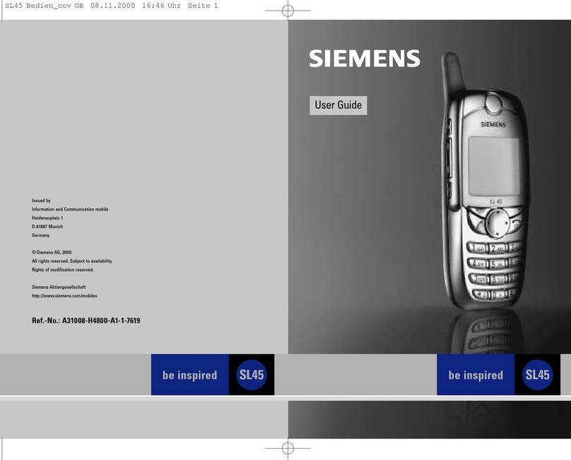
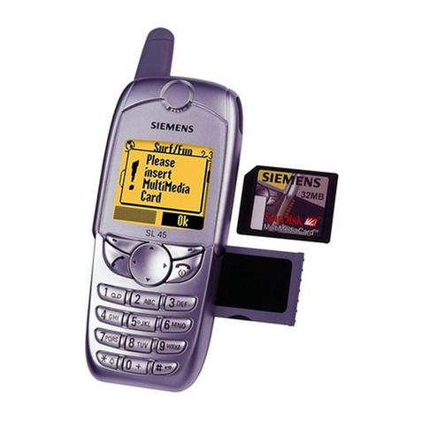
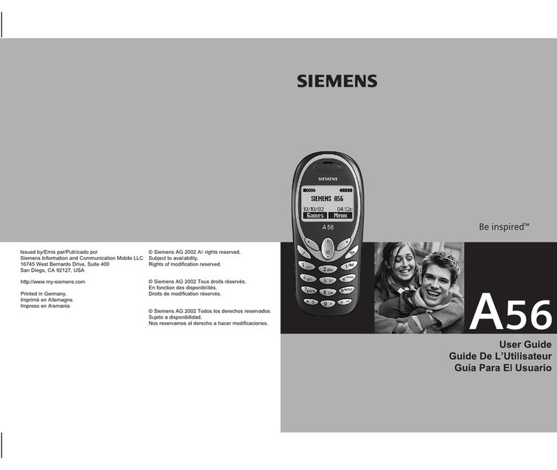
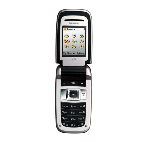
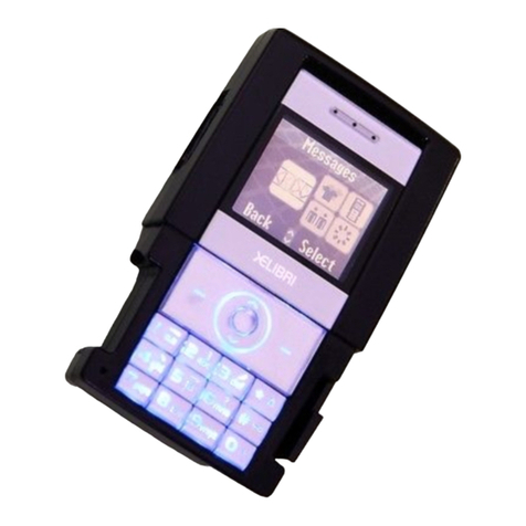
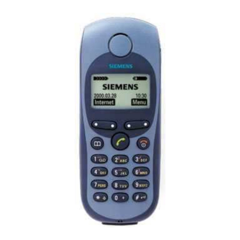
Siemens Gigaset SL55 Operator's manual

Customer Care
V 1.0 Page 1of 52 ICM MP CCQ GRM
SL55 Company Confidential © Copyright Siemens AG 06/03
SL55
Level 2.5e
Repair Documentation
V 1.0
Version Date Department Notes to change
V 1.00 June 2003 ICM MP CCQ GRM New document

Customer Care
V 1.0 Page 2of 52 ICM MP CCQ GRM
SL55 Company Confidential © Copyright Siemens AG 06/03
Table of Contents:
1LIST OF AVAILABLE LEVEL 2,5E PARTS SL55 .............................................. 4
2REQUIRED EQUIPMENT FOR LEVEL 2,5E...................................................... 5
3REQUIRED SOFTWARE FOR LEVEL 2,5E SL55 ............................................. 5
4RADIO PART ...................................................................................................... 6
4.1 Power Supply RF-Part .................................................................................... 7
4.2 Frequency generation .................................................................................... 7
4.2.1 Synthesizer: The discrete VCXO (26MHz) ...........................................................................7
4.2.2 Synthesizer: LO1 ..................................................................................................................8
4.3 Frontendmodul (Electrical Antenna Switch) .............................................. 10
4.4 Receiver......................................................................................................... 11
4.4.1 Receiver: EGSM900/GSM1800/GSM1900 –Filter to Demodulator....................................11
4.4.2 IC Overview ........................................................................................................................13
4.5 Transmitter.................................................................................................... 15
4.5.1 Transmitter: Modulator and Limited Amplifier.....................................................................15
4.5.2 Transmitter: and Power Amplifier .......................................................................................17
5LOGIC / CONTROL........................................................................................... 18
5.1 Overview of Hardware Structure ................................................................. 18
5.1.1 Logic Block Diagram...........................................................................................................18
5.1.2 Block Diagram SL55 Control Part.......................................................................................19
5.1.3 EGOLD+ .............................................................................................................................21
5.1.4 SRAM .................................................................................................................................25
5.1.5 FLASH ................................................................................................................................25
5.1.6 SIM .....................................................................................................................................25
5.1.7 Vibration Motor ...................................................................................................................26
5.1.8 Hall sensor + magnet..........................................................................................................26
6POWER SUPPLY.............................................................................................. 27
6.1 Power Supply ASIC ...................................................................................... 27
6.1.1 Pinout diagram ...................................................................................................................28
6.1.2 Power Supply Diagram .......................................................................................................29
6.1.3 Power Supply Operating mode:..........................................................................................30
6.1.4 Power Supply Functions: ....................................................................................................31
6.2 Battery ........................................................................................................... 33
6.3 Charging Concept......................................................................................... 33
7INTERFACES.................................................................................................... 38
Customer Care
V 1.0 Page 3of 52 ICM MP CCQ GRM
SL55 Company Confidential © Copyright Siemens AG 06/03
7.1 Vibra............................................................................................................... 38
7.2 Earpiece......................................................................................................... 38
7.3 Microphone ................................................................................................... 40
7.4 Battery ........................................................................................................... 40
7.5 IO Connector with ESD protection.............................................................. 41
7.5.1 IO Connector – New Slim Lumberg....................................................................................41
7.5.2 ESD Protection with EMI filter.............................................................................................43
7.6 SIM ................................................................................................................. 44
7.7 MMI Connector.............................................................................................. 45
8ACOUSTIC ........................................................................................................ 47
8.1 Microphone ................................................................................................... 47
8.1.1 Mechanical..........................................................................................................................47
8.1.2 Electrical .............................................................................................................................47
8.2 Soundchip ..................................................................................................... 48
8.3 Earpiece/Loudspeaker ................................................................................. 49
8.3.1 Mechanical..........................................................................................................................49
8.3.2 Electrical .............................................................................................................................49
9DISPLAY AND ILLUMINATION ........................................................................ 50
9.1 Display........................................................................................................... 50
9.2 Illumination ................................................................................................... 50
10 KEYBOARD ................................................................................................... 51
11 IRDA............................................................................................................... 52

Customer Care
V 1.0 Page 4of 52 ICM MP CCQ GRM
SL55 Company Confidential © Copyright Siemens AG 06/03
1 List of available level 2,5e parts SL55
ID-No Type Name, Location Part-No.
D171 IC EGOLD+ V3.1 F M42 V39197-F5019-F415
V151 Diode Diode_KB7 V20840-D5062-D670
Z172 Quarz Quarz EGOLD+ V30145-F102-Y10
R212 Varistor Varistor IO connector V39197-F5015-F351
R213 Varistor Varistor IO connector V39197-F5015-F351
R215 Varistor Varistor IO connector V39197-F5015-F351
R140 Resistor Resistor Sound/Clock V24852-C -X
R160 Resistor Resistor PaRamp V24852-C -X
R172 Resistor Resistor Quarz EGOLD+ V24852-C -X
R216 Resistor Resistor Audio V24852-C -X
R217 Resistor Resistor Audio V24852-C -X
R630 Resistor Resistor PA V24852-C -X
R659 Resistor Resistor RX V24852-C -X
R662 Resistor Resistor RX V24852-C -X
R707 Resistor Resistor AFC V24852-C -X
R728 Resistor Resistor VREGRF2 V24852-C -X
Z211 Filter Logic/IO_Interface V39197-F5000-F116
D400 IC Application_Processor V20820-L6117-D670
V190 Diode Diode_SIM Interface V20840-D53-D670
V191 Diode Diode_SIM Interface V20840-D53-D670
V320 Diode Diode_Akku/Vibra V20840-D53-D670
N281 IC Volt.Regulator_Light V20810-C6106-D670
N282 IC Volt.Regulator_Light V20810-C6098-D670
V212 Transistor Transistor _Light V20830-C1112-D670
V213 Transistor Transistor _Vibra V20830-C1112-D670
V361 Transistor Transistor_Charger V20830-C1110-D670
N361 IC Vol.Regulator V20810-C6105-D670
D361 IC ASIC_Salzburg light V30145-J4682-Y47
R192 Resistor Resistor_ SIM Interface V24842-C -X
R376 Resistor Resistor_ASIC V24842-C -X
R608 Resistor Resistor_PA switch V24842-C -X
R730 Resistor Resistor VREGRF1 V24842-C -X
Z600 IC Power_Amplifier V39197-F5005-F487
D650 IC Ant_Switch_Diplexer V39197-F5006-F936
R700 Resistor Temp_Resistor V39120-F4223-H
Z700 Quartz Oszillator_26MHz V39197-F5007-F381
V700 Diode Capa_Diode V20840-D68-D670
D720 IC Tranceiver V39197-F5014-F603
Z680 Filter RX Filter V39197-F5005-F917

Customer Care
V 1.0 Page 5of 52 ICM MP CCQ GRM
SL55 Company Confidential © Copyright Siemens AG 06/03
D750 VCO TX VCO V20820-L6109-D670
Z750 Filter TX Filter V30145-K280-Y242
S851 Switch Magnetic switch RF V39197-F5008-F63
S852 Switch Magnetic switch Logic V39197-F5008-F63
2 Required Equipment for Level 2,5e
- GSM-Tester (CMU200 or 4400S incl. Options)
- PC-incl. Monitor, Keyboard and Mouse
- Bootadapter 2000/2002 (L36880-N9241-A200)
- Adapter cable for Bootadapter due to new Lumberg connector (F30032-P226-A1)
- Troubleshooting Frame SL55 (F30032-P260-A1)
- Power Supply
- Spectrum Analyser min. 4GHz
- Active RF-Probe incl. Power Supply
- Oscilloscope incl. Probe
- RF-Connector (N<>SMA(f))
- Power Supply Cables
- Dongle (F30032-P28-A1) if USB-Dongle is used a special driver for NT is required
- BGA Soldering equipment
Reference: Equipment recommendation V1.2
(downloadable from the technical support page)
3 Required Software for Level 2,5e SL55
- Windows NT Version4
- Winsui version1.42 or higher
- Software for GSM-Tester ( Cats(Acterna/Wiltek) or CMU-GO(Rohde&Schwarz) )
- Software for reference oscillator adjustment
- Internet unblocking solution
- Dongle driver for USB-Dongle if used with WIN NT4
Information: All software is downloadable from the technical support page

Customer Care
V 1.0 Page 6of 52 ICM MP CCQ GRM
SL55 Company Confidential © Copyright Siemens AG 06/03
4 Radio Part
The radio part is designed for Tripple Band operation, covering EGSM900, GSM1800 as
well as GSM 1900 frequencies, and can be divided into 4 Blocks.
o RF power amplifier (RF9340) and PA Buffer/Limiter (Infineon PMB2256)
o Frontend Module (Epcos M002)
o 26 MHZ reference VCO
o Tranceiver (Infineon Smarti DC PMB 6259 for 900/1800/1900)
The functionality of the DC SMARTI are:
- All VCOs and PLLs are build in
- Direct Modulator
- Direct Demodulator
- Including the active part of the reference oscillator.
The RF-Part has it´s own power supply realised by a voltage regulator which is located
inside the ASIC. The voltages for the logic part are generated by the Power-Supply ASIC
too.
The transmitter part converts the I/Q base band signals supplied by the logic (EGOLD+)
into RF-signals with characteristics as defined in the GSM recommendation
(www.etsi.org). After amplification by a power amplifier the signal is radiated via the
internal antenna.
The receiver part converts the received GMSK signal supplied by the antenna into IQ
base band signals which are further processed by the logic (EGOLD+).
The synthesizer generates the required frequencies for the transmitter and receiver. A
26MHz oscillator is acting as a reference frequency.
Restrictions:
The mobile phone can never transmit and receive in both bands simultaneously. Only the
monitor time slot can be selected independently of the frequency band. Transmitter and
receiver can of course never operated simultaneously.

Customer Care
V 1.0 Page 7of 52 ICM MP CCQ GRM
SL55 Company Confidential © Copyright Siemens AG 06/03
4.1 Power Supply RF-Part
The voltage regulator for the RF-part is located inside the ASIC D361.(see chapter 5.2).It
generates the required 2,85V “RF-Voltages” named VREGRF1 and VREGRF2.
The following components are supplied by:
VREGRF1
· 26 MHz reference oscillator
· VCO
· PLL
VREGRF2
· Modulators
· RX mixers
· Limiter amplifier
The voltage regulator RFREG 1 is controlled by 1.8V (RF_EN (RF REG G2)),RFREG2 is
controlled by SLEEP1_N (on/off Control H1) and SLEEP2_N (on/off Control F1). IF one of these
signals is high the regulator is enable. SLEEP1_N is connected to the signal VCXOEN
(Miscellaneous R6) provided by the EGOLD+. RF_EN and SLEEP2_N is connected to 1.8 V
provided by the ASIC (REG2 A7) The temporary deactivation is used to extend the stand by
time.
Circuit diagram
4.2 Frequency generation
4.2.1 Synthesizer: The discrete VCXO (26MHz)
The SL55 mobile phone is using a reference frequency of 26 MHz signal that is created by
a partly integrated VCXO. ON/OFF signal (VCXOEN (Miscellaneous R6)) comes from the
EGOLD+. A Colpitts-oscillator is used with a post connected buffer stage integrated in the
Smarti. For temperature measurements of the VCXO a temperature resistance (R700) is
used. The resistor is placed near the VCXO. The measurement result TVCXO is reported
to the EGOLD+ (Analog Interface P3) via R138 as the signal TENV.
The frequency of the reference oscillator can be adjusted by the EGOLD+ via a PNM-
modulated AFC-signal.
The signal leaves the SMARTI as BB_SIN26M at pin 4 to be further used from the
EGOLD+ (D171 (functional T3)).
The required voltage VREGRF1 is provided by the ASCI D361
V
REGRF1
V
REGRF2

Customer Care
V 1.0 Page 8of 52 ICM MP CCQ GRM
SL55 Company Confidential © Copyright Siemens AG 06/03
Circuit diagram
4.2.2 Synthesizer: LO1
The local oscillator (LO1) consists of a PLL inside the Smarti DC (D720), an external loop
filter. The VCO is build in.
The first local oscillator is needed to generate frequencies which enables the transceiver
IC to demodulate the receiver signal and to perform the channel selection in the TX part.
The LO1/PLL part is switched on with PLLON (pin 5) from the EGOLD+ (D171 (GSM TDMA
Timer F16)). The PLL settings are programmed by the 3 wire bus RFCLK (pin 1), RFDATA
(pin2) and RFSTR (pin3). The LO frequency is 4 times the RX/TX frequency for EGSM 900
and 2 times for GSM1800/1900.
This LO1 frequency range
The required voltage VRREGRF1 is provided by the ASIC D361
from EGOLD
to EGOLD+
AFC

Customer Care
V 1.0 Page 9of 52 ICM MP CCQ GRM
SL55 Company Confidential © Copyright Siemens AG 06/03
Block diagram
Circuit diagram
External
loopfilter
External
loopfilter

Customer Care
V 1.0 Page 10of 52 ICM MP CCQ GRM
SL55 Company Confidential © Copyright Siemens AG 06/03
4.3 Frontendmodul (Electrical Antenna Switch)
EGSM900/GSM1800/GSM1900 <> Receiver/Transmitter
The frontend has two functions.
- to select the different GSM bands
- to switch between RX and TX mode
Inside the frontendmodul SAW filters are integrated in the RX paths.
Mode Selection FEM 1 / VC1 FEM 2 / VC2 FEM 3 / VC3
EGSM900 RX LOW LOW LOW
EGSM900 RX HIGH LOW LOW
GSM1800 RX LOW LOW LOW
GSM1800 TX LOW HIGH LOW
GSM1900 RX LOW LOW HIGH
GSM1900 TX LOW HIGH LOW
to
Demodulator
to Antenna
from
P
A
Control Signals
from Smarti

Customer Care
V 1.0 Page 11of 52 ICM MP CCQ GRM
SL55 Company Confidential © Copyright Siemens AG 06/03
D650
Top View
4.4 Receiver
4.4.1 Receiver: EGSM900/GSM1800/GSM1900 –Filter to Demodulator
From the antenna switch, up to the demodulator the received signal passes the following
blocks to get the demodulated baseband signals for the EGOLD+:
Inside Z650 Smarti Smarti Smarti
Filter: The EGSM900, GSM1800 and GSM 1900 filters are located inside the frontend
module. The Filter are centred to a frequency of 942,5MHz for EGSM900, 1847,5MHz for
GSM1800 and 1960MHZ for GSM1900.
LNA: The LNA´s (EGSM900/GSM1800/GSM1900) are located inside the Smarti. The
LNA can be switched in HIGH (On) and LOW (Off) mode and is controlled by the Smarti
depending on EGOLD+ information.
Demodulator: The Smarti DC consists of a direct conversion receiver for GSM
900/1800/1900. The amplified RF signal is converted by a quadrature demodulator to the
final outputsignals at baseband frequency. The LO signals are generated by a divider by 4
for the GSM900 band and by a divider by 2 for GSM1800 and GSM1900 band.
The resulting in-phase and quadratursignals are fed into two baseband low pass filters
and the PGC amplifier chain. The baseband filter provide a suppression of inband-
blocking and adjacent channel interferers.
PGC: After baseband filtering the signal is fed into a PGC amplifier chain. The baseband
amplifier offers 78 dB programmable gain with 2 dB steps. Due to the high baseband gain
(58 dB), DC offsets can corrupt the signal at the baseband outputs. Differential offset
voltages are reduced by an internal offset compensation circuit. The control is realised
through the EGOLD+ signals (RFDATA; RFCLK; RFSTR.(RF Control J15, J16, J17).
The required voltages VREGRF1 and VREGRF2 are provided by the ASIC D361
Filter LNA PGC
Demodulator

Customer Care
V 1.0 Page 12of 52 ICM MP CCQ GRM
SL55 Company Confidential © Copyright Siemens AG 06/03
Circuit diagram
Top view
to EGOLD+
progr. signals from
antenna

Customer Care
V 1.0 Page 13of 52 ICM MP CCQ GRM
SL55 Company Confidential © Copyright Siemens AG 06/03
4.4.2 IC Overview
IC Overview
Smarti
RX Path
TX Path
RX/TX Path

Customer Care
V 1.0 Page 14of 52 ICM MP CCQ GRM
SL55 Company Confidential © Copyright Siemens AG 06/03

Customer Care
V 1.0 Page 15of 52 ICM MP CCQ GRM
SL55 Company Confidential © Copyright Siemens AG 06/03
4.5 Transmitter
4.5.1 Transmitter: Modulator and Limited Amplifier
The GMSK modulated signal is generated in the direct modulator. That means, that the
modulators are working directly on the final output frequency. The LO frequency is divided
by 2 or 4, depending on the GSM band. There are two modulators, one for the two higher
bands and the other for the two lower bands..
The required voltages VREGRF1 and VREGRF2 are provided by the ASIC D361
The actual signal is fed into a limiting amplifier with 3 dB amplification which also provides
a signal path for the high band and one for the low band.
Mode Selection Pin9 / EN (TXON1/D171_J14)) Pin10 / BS (OSW1/D720_25)
EGSM900 limiter enable HIGH LOW
GSM1800 limiter enable HIGH HIGH
TopView ICOverview
The next stage in the low band line-up is a TX saw filter.
to P
A
from EGOLD+

Customer Care
V 1.0 Page 16of 52 ICM MP CCQ GRM
SL55 Company Confidential © Copyright Siemens AG 06/03
In the high band no SAW filter is required.

Customer Care
V 1.0 Page 17of 52 ICM MP CCQ GRM
SL55 Company Confidential © Copyright Siemens AG 06/03
4.5.2 Transmitter: and Power Amplifier
The output signals (CS_PA_IN , and GSM_PA_IN) from the limited amplifier are led to the
power amplifier (Z600) passing a matching circuit. contains two separate 3-stage amplifier
chains for GSM 850/900 and GSM 1800/1900. The control of the output power is handled
via one Vapc port. The power control circuit itself is integrated in the PA module. The
EGOLD generates the power control signal PA-RAMP. The band selection switching is
done via OSW1 from the Smarti IC.
The required voltage BATT+ is provided by the battery.
The required voltage VREGRF2 for the power control circuit is provided by the ASIC D361.
Blockdiagram of R 340 (PA)
to Ant.
connector
from limitter
amplfier

Customer Care
V 1.0 Page 18of 52 ICM MP CCQ GRM
SL55 Company Confidential © Copyright Siemens AG 06/03
5 Logic / Control
5.1 Overview of Hardware Structure
5.1.1 Logic Block Diagram
RF Control
RF-
Part

Customer Care
V 1.0 Page 19of 52 ICM MP CCQ GRM
SL55 Company Confidential © Copyright Siemens AG 06/03
5.1.2 Block Diagram SL55 Control Part

Customer Care
V 1.0 Page 20of 52 ICM MP CCQ GRM
SL55 Company Confidential © Copyright Siemens AG 06/03
Other manuals for Gigaset SL55
4
Table of contents
Other Siemens Cell Phone manuals

Siemens
Siemens CX65 User manual

Siemens
Siemens A35 User manual

Siemens
Siemens S25 User manual

Siemens
Siemens MC60 User manual

Siemens
Siemens C62 User manual

Siemens
Siemens S2588 User manual

Siemens
Siemens Mobile User manual

Siemens
Siemens CX65 User manual

Siemens
Siemens A75 User manual

Siemens
Siemens S35i User manual

Siemens
Siemens RUGGEDCOM i802 User manual

Siemens
Siemens CX70 User manual

Siemens
Siemens M65 User manual

Siemens
Siemens SIMATIC S7 CP340 Operating instructions

Siemens
Siemens ST60 User manual

Siemens
Siemens CF62 User manual

Siemens
Siemens A70 User manual

Siemens
Siemens C65 User manual

Siemens
Siemens CX75 User manual

Siemens
Siemens U15 User manual