Siemens CCWC1335-LP User manual

Fire Safety & Security Products
Siemens Building Technologies
1/3 inch High-Res Extended
Dynamic Day/Night Camera
CCWC1335-LP
CCWC1335-MP
Instruction Manual

Data and design subject to change without notice. / Supply subject to availability.
© 2005 Copyright by
Siemens Building Technologies AG
We reserve all rights in this document and in the subject thereof. By acceptance of the document the recipient acknowledges these rights
and undertakes not to publish the document nor the subject thereof in full or in part, nor to make them available to any third party without our
prior express written authorization, nor to use it for any purpose other than for which it was delivered to him.
Dear Customer
By selecting this SIEMENS product, you have chosen a professional device that
guarantees the highest possible quality and reliability. We would like to thank you
very much for your confidence in our products and kindly ask you to read the
following instructions carefully before installing and using the product, in order to
take full advantage of all quality features included in this product line.
WARNING
To reduce the risk of fire or electrical shock, do not expose this product to rain or
moisture. It should be installed by a qualified service person and should conform to
all local codes. Please connect the equipment to a 12 V DC or 24 V AC Class 2
power supply if the LP camera model is to be installed.

3
Siemens Building Technologies
Fire Safety & Security Products 03.2005
Contents
1General Information ................................................................................5
1.1 General Safety Precautions ......................................................................5
1.2 Electromagnetic Compatibility (EMC) .......................................................5
1.3 Manufacturer's Declaration of Conformity.................................................6
2Ordering Data ..........................................................................................6
3Package contents....................................................................................6
4General Guidelines .................................................................................8
4.1 Operation & Storage .................................................................................8
4.2 Cleaning ....................................................................................................8
4.3 Transportation ...........................................................................................8
4.4 CCD Characteristics..................................................................................8
5Technical Specifications ........................................................................9
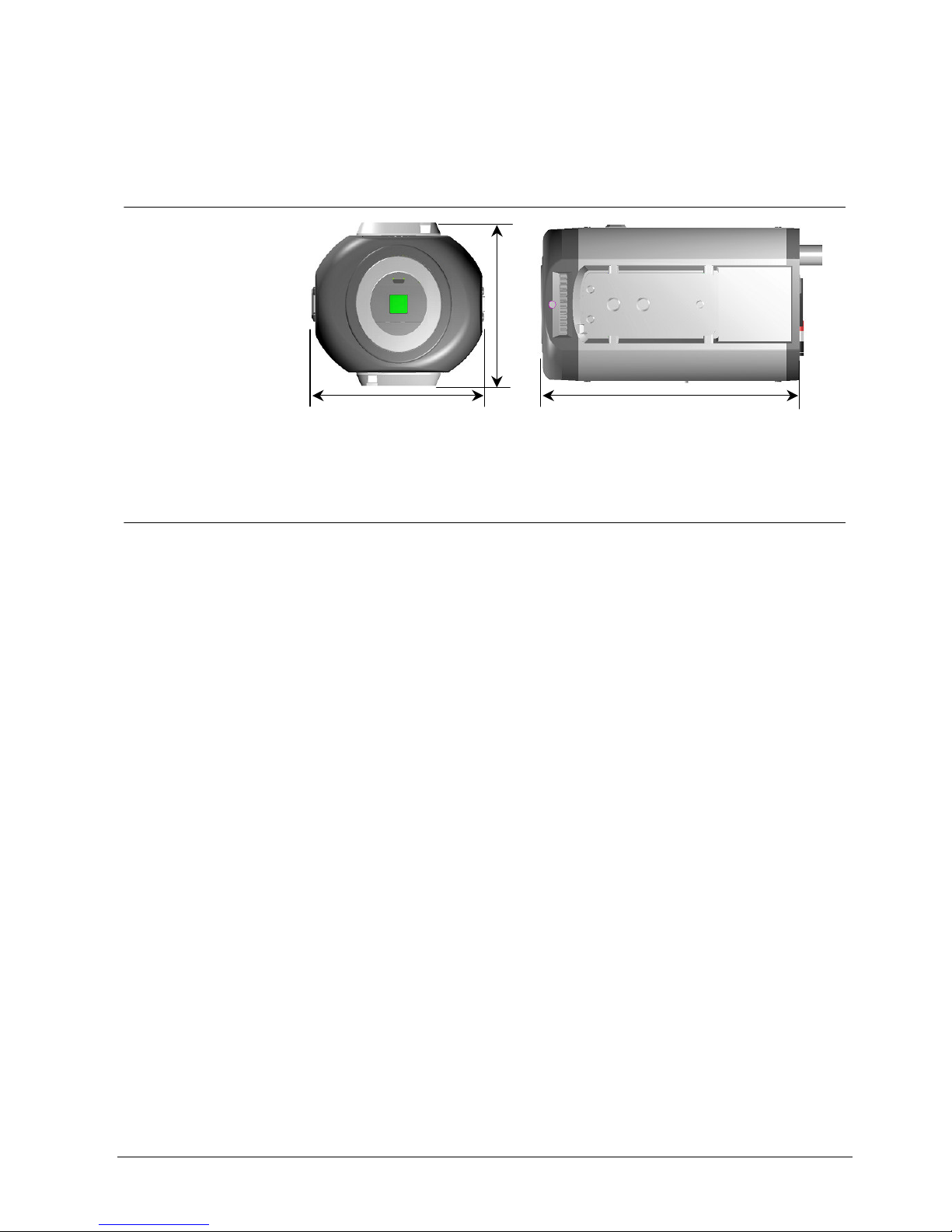
5.1 Dimensions ...............................................................................................9
5.2 Product Specifications ..............................................................................9
6Camera Parts & Connections ..............................................................11
6.1 Camera Parts ..........................................................................................11
6.2 Connector Pin Definition .........................................................................12
6.3 OSD Setting Hierarchy............................................................................13
7Installing the Camera............................................................................14
7.1 Installation ...............................................................................................14
7.2 Function Settings ....................................................................................14
7.2.1 D/N MODE ..............................................................................................15
7.2.2 D/N LEVEL..............................................................................................16
7.2.3 D/N DELAY .............................................................................................16
7.2.4 EXPOSURE ............................................................................................17
7.2.5 SHUTTER ...............................................................................................18
7.2.6 SENS UP ................................................................................................18
7.2.7 GAIN .......................................................................................................18
7.2.8 SYNC ......................................................................................................19
7.2.9 BLC .........................................................................................................19
7.2.10 WHITE BAL............................................................................................20
7.2.11 GAMMA...................................................................................................21
7.2.12 APERTURE.............................................................................................21
7.2.13 EZOOM ...................................................................................................21
7.2.14 MIRROR..................................................................................................22
7.2.15 PRIVACY ZONE .....................................................................................22
7.2.16 OPTION ..................................................................................................23
7.2.16.1 BLEMISH DET .......................................................................................23
7.2.16.2 BACK FOCUS........................................................................................23
7.2.16.3 ALARM FUNC........................................................................................24
7.2.16.4 ALARM OUT ..........................................................................................24
7.2.16.5 ALARM DELAY......................................................................................24
7.2.16.6 ALARM TEXT.........................................................................................24
7.2.16.7 CHROMA ...............................................................................................24
7.2.16.8 CAMERA TEXT......................................................................................24
7.2.17 REMOTE.................................................................................................25
7.2.17.1 MODEL ..................................................................................................25
7.2.17.2 ADDRESS..............................................................................................25
7.2.17.3 BAUD RATE...........................................................................................25
7.2.17.4 PROTOCOL...........................................................................................26

4
Siemens Building Technologies
Fire Safety & Security Products 03.2005
7.2.17.5 SOFT VER .............................................................................................26
7.2.17.6 Pattern....................................................................................................26
7.2.18 NEXT/ BACK...........................................................................................26
7.2.19 EXIT ........................................................................................................26
7.2.20 CANCEL..................................................................................................26
7.2.21 DEFAULT................................................................................................26
8Index .......................................................................................................27

General Information
5
Siemens Building Technologies
Fire Safety & Security Products 03.2005
1 General Information
1.1 General Safety Precautions
Read these instructions carefully before connecting the camera in order to avoid
damage caused by improper installation or use.
Installation may be done only by authorized personnel according to the local
safety regulations.
Operate the camera only with the designated voltage.
Follow the safety instructions for the camera.
Never use the camera for purposes other than those designated.
Repairs and adjustments to the camera may be done only by authorized
personnel.
If liquids or objects get into the housing, disconnect the camera from the power
supply and have it checked by your authorized dealer before using it again.
(Danger of electric shock!)
This equipment has been tested and found to comply with the limits for a Class
B digital device. These limits are designed to provide reasonable protection
against harmful interference in a residential installation.
This equipment may generate, uses and can radiate radio frequency energy
and, if not installed and used according to instructions, may cause harmful
interference with radio communications.
Be aware that any modifications not explicitly approved in this manual may void
your equipment warranty.
The shielded interface cable recommended in this manual must be used with
this equipment in order to comply with the limits for a digital output device.
1.2 Electromagnetic Compatibility (EMC)
This product has been designed for use in general-purpose CCTV applications in a
residential, business or industrial environment. Please contact the supplier of this
product before you install it in medical and/or intrinsically safe applications or in an
industrial EMC environment.
To ensure normal operation and to avoid EMC problems, the product must be
installed according to the currently valid EMC installation guidelines.
To meet the CE norms, enclosed EMI-cores should be applied to the Y/C and
power cable (see chapter 7.1).

Ordering Data
6
Siemens Building Technologies
Fire Safety & Security Products 03.2005
1.3 Manufacturer's Declaration of Conformity
EU Directive
The following applies to the equipment described in this instruction manual:
The product fulfils the requirements of EU directive 89/336/EEC with regard to
“electromagnetic compatibility“ and EU directive 73/23/EEC, the ”low-voltage
directive“, according to EN 60065.
Area of Use Requirements for
Emitted Interference Noise Protection
Industry and residential EN 55022:1998 Class B
EN 61000-3-2 A2: 1998
EN 61000-3-3: 1995
EN 50130-4:1998
The EU certificate of conformity is available for official inspection and is held at:
Siemens Building Technologies
SBT FSP DE
Siemensallee 84
76187 Karlsruhe, Germany
2 Ordering Data
Designation Order No. Approx. Weight
(kg)
CCWC1335-LP
1/3” High-Resolution Extended Dynamic Day/Night
Camera 12 V DC/24 V AC
2GF1183-8FC 0.55
CCWC1335-MP
1/3” High-Resolution Extended Dynamic Day/Night
Camera 90 ~ 260 V AC
2GF1183-8FB 0.55
Accessories, not included in delivery!
PSU230-12
Power supply unit for 12 V DC cameras
2GF1800-8BE 0.12
CAPA2410-P
Power supply unit for 24 V AC cameras
2GF1800-8BJ 0.30
3 Package contents
CCD camera
C/CS-mounting adapter
EMI core (-LP: 1pcs, -MP: 2pcs)
CD containing remote control software and a detailed operating manual

Package contents
7
Siemens Building Technologies
Fire Safety & Security Products 03.2005
Quickstart manual

General Guidelines
8
Siemens Building Technologies
Fire Safety & Security Products 03.2005
4 General Guidelines
4.1 Operation & Storage
Avoid filming very bright objects (such as lighting fixtures) for an extended
period.
Do not operate or store the unit in the following locations:
– Extremely hot or cold places.
– Close to sources of strong magnetic fields.
– Close to sources of powerful electromagnetic radiation, such as radios or TV
transmitters.
– In humid or excessively dusty places.
– Where exposed to mechanical vibrations.
– Close to fluorescent lamps or objects reflecting light.
– Under unstable or flickering light sources.
Do not attempt to service this unit yourself unless you are authorized to do so.
Opening the camera may expose you to dangerous voltages or other hazards.
Refer all servicing to qualified personnel only.
4.2 Cleaning
Do not touch the imaging surface of sensor. Use a soft cloth moistened with
alcohol to clean the surface if it is touched accidentally.
4.3 Transportation
Use the original packing material or materials of equal quality.
4.4 CCD Characteristics
The following conditions may be observed when using a CCD camera. These are
inherent in the design and do not stem from any fault in the camera itself.
Vertical smear This phenomenon occurs when viewing a very bright object.
Patterned noise This is a fixed pattern, which may appear over the entire
monitor screen when the camera is operated at a high
temperature.
Jagged picture When viewing stripes, straight lines, or similar patterns, the
image on the screen may appear jagged.

Technical Specifications
9
Siemens Building Technologies
Fire Safety & Security Products 03.2005
5 Technical Specifications
5.1 Dimensions
5.2 Product Specifications
Image area 4.9 x 3.7 mm
Pickup elements 752 (H) x 582 (V) pixels 1/3” WD CCD
Scanning system 2:1 interlace PAL V: 50 Hz, H: 15,625 Hz
Sync system Internal/ line lock selectable (AC only)
Video output BNC composite, Y/C output
Lens mount CS mount
Resolution > 480 TV lines (Horizontal)
Gamma correction 0.45, 1.0 selectable
CL: 0.4 lux @F=1.4 (AGC 30dB , 50IRE video output)Minimum illumination
BW :0.08 lux @ F=1.4 (AGC 30dB , 50IRE Video
Output)
S/N ratio > 50 dB
12 V DC ±10% regulated power supply
24 V AC ±10%, 50 Hz
Power source
100~240 V AC ±10%, 50 Hz
Power consumption 8 VA (max) as DN filter moving
Ambient conditions -10 ~ 50 °C/ 95% max relative humidity, no condensation
Dimensions in mm 122 (L) x 72 (W) x 63 (H)
Weight 550 g (max.)
Shutter control Auto: 1/50 to 1/50,000 Sec.
Manual: 1/50, 1/120, 1/250, 1/500, 1/1K, 1/2K, 1/5K,
1/10K, 1/20K, 1/50K
Slow shutter 2X, 5X, 10X, 20X, 40X, 80X, 160X, 320X
Wide dynamic OFF/ON (X 128)
Gain control Selectable (OFF, Normal, Turbo); gain (up to 30 dB)
Backlight compensation 6 area selectable: Center 1, Center 2,Up Half, Low Half,
Middle Low, Middle High
72 122
63

Technical Specifications
10
Siemens Building Technologies
Fire Safety & Security Products 03.2005
Privacy zone 8 blocks (max)
D/N mechanical Dual moving OLPF/glass
D/N mode AUTO, MAUNAL, COLOR, MONO
D/N level HIGH, MID, LOW
D/N DLY 0, 5, 10, 15, 20 selectable
Digital zoom X 2.6
Aperture correction HIGH, MID, LOW
White balance ATW1:2600°K~6000°K
ATW2: 2500°K~10,000°K
Manual: 32 steps by push button for R and B
Iris control Video / DC iris for galvanometer lens
Camera text 16 characters
OSD control 5 control keys on the side-panel of camera
Default settings Default setting restored by pushing the DEFAULT button
Remote control RS-485
Alarm IN 1CH
Alarm OUT NC or NO selectable

Camera Parts & Connections
11
Siemens Building Technologies
Fire Safety & Security Products 03.2005
6 Camera Parts & Connections
6.1 Camera Parts
1. Back focus adjustment ring ①
2. Back focus lock screw ②
3. Tripod mount hole ③
4. IRIS connector ④
5. Power indicator ⑤
6. Video output ⑥
7. Power cord (or power terminal) ⑦

Camera Parts & Connections
12
Siemens Building Technologies
Fire Safety & Security Products 03.2005
8. External control terminal: (From right to left) ⑧
Pin Pin Definition Description
1 Data +
2 Data –
RS485 signal
3 Alarm IN
4 GND
If the alarm IN & GND are shorted, the alarm function will be active.
(Please set ALARM FUNC to ON in OSD menu.)
5 Alarm OUT
6 COM
Alarm output circuit.
7 B/W
8 C/L
9 GND
If D/N MODE is set in manual mode, this function will be enabled. If
B/W & GND are shorted, the video signal is monochrome. If C/L &
GND are shorted, the video signal is color.
9. Y/C terminal ⑨
10. Video/ DC lens selection ⑩
11. OSD control button ⑪
12. PC connection port: For factory testing only, the user is not recommended to
use this function. ⑫
6.2 Connector Pin Definition
IRIS pin assignment
Video Lens DC Lens
1. +12V 1. Damp-
2. NC 2. Damp+
3. VIDEO 3. Drive +
4. GND 4. Drive-
Y/ C terminal
1 GND
2 GND
3 Y (luminance, 1 Vpp, 75 Ω)
4 C (chrominance, 0.3 Vpp (burst), 75 Ω)

Camera Parts & Connections
13
Siemens Building Technologies
Fire Safety & Security Products 03.2005
6.3 OSD Setting Hierarchy
OSD SETTING
(P1)
(P2)

Installing the Camera
14
Siemens Building Technologies
Fire Safety & Security Products 03.2005
7 Installing the Camera
7.1 Installation
1. Connect the BNC cable to the video output ⑥
2. Connect the power source to the power terminal
Caution:
If using a DC supply, make sure the polarity is correct. Incorrect connection may cause malfunction
and/or damage to the camera.
3. To reduce radiation sufficiently, please wind one turn around the core, see figure
below.
Location Core illustration for what camera
Power cable
LP
Y/C cable
LP / MP
EIM-0050751G
4. Adjust the backfocus
For backfocus adjustment, please loosen screw ②, set the camera to AES mode
(see section 7.2.16.2: BACK FOCUS), then the rotate backfocus wheel ①until a
sharp image appears. Tighten screw ②.
7.2 Function Settings
Select ENTER on the OSD; the menu will appear on the display and will disappear
after 30 seconds if no action occurs. The shaded setting area means an item is
selected and it keeps blinking.

Installing the Camera
15
Siemens Building Technologies
Fire Safety & Security Products 03.2005
7.2.1 D/N MODE
Fig. 1 D/N MODE
This function sets the Day/Night mode to automatic, color, B/W or external control
of setting to B/W or color.
Move the cursor to the position shown in Fig. 1.
Use the LEFT/ RIGHT button to select AUTO, MONO, COLOR or MANUAL mode.
AUTO When set to this mode, the camera will change to COLOR mode or B/W mode
automatically depending on a subject’s brightness. (When GAIN sets OFF, auto
function can’t be selected).
MONO When set to this mode, the camera remains in B/W mode
COLOR When set to this mode, the camera will remain in color mode.
MANUAL When set to this mode, the camera will be switched to color or B/W mode manually
according to a signal received at a terminal on the rear panel.
D/N MODE AUTO
D/N LEVEL HIGH
D/N DELAY 15 sec
EXPOSURE <ALC>
SHUTTER 1/50
SENS UP OFF
GAIN NORMAL
SYNC LL:000
BLC OFF
NEXT EXIT CANCEL DEFAULT

Installing the Camera
16
Siemens Building Technologies
Fire Safety & Security Products 03.2005
7.2.2 D/N LEVEL
Fig. 2 D/N LEVEL
This function sets the filter switchover point to high, low or medium.
Configure a switchover point from COLOR mode to B/W mode. Move the cursor to
the position shown in Fig. 2. Use the LEFT/ RIGHT button to select HIGH, LOW or
MID. This setting is only relevant if the D/N mode is set to AUTO.
LOW The brightness for switchover from COLOR to B/W mode is approx. 1 lux.
MID The brightness for switchover from COLOR to B/W mode is approx. 2 lux.
HIGH The brightness for switchover from COLOR to B/W mode is approx. 4 lux.
7.2.3 D/N DELAY
Fig. 3 D/N DELAY
This function sets the DELAY time for the D/ N function
Move the cursor to the position shown in Fig. 3.
Use the LEFT/ RIGHT button to select 0, 5, 10, 15 or 20 sec for delay of DN filter
moving timing. This setting is only relevant if the D/N mode is set to AUTO.
Info:
If using the camera together with infrared illumination, we recommend using video lenses with
special IR coating to prevent a physically based focus-shift between daylight and IR illumination.
We recommend using the D/N mode “MANUAL” when the camera is used with discrete IR
illumination in order to prevent the continual switching between color and B/W mode that might occur
with the D/N mode “AUTO”.
D/N MODE AUTO
D/N LEVEL HIGH
D/N DELAY 15 sec
EXPOSURE <ALC>
SHUTTER 1/50
SENS UP OFF
GAIN NORMAL
SYNC LL:000
BLC OFF
NEXT EXIT CANCEL DEFAULT
D/N MODE AUTO
D/N LEVEL HIGH
D/N DELAY 15 sec
EXPOSURE <ALC>
SHUTTER 1/50
SENS UP OFF
GAIN NORMAL
SYNC LL:000
BLC OFF
NEXT EXIT CANCEL DEFAULT

Installing the Camera
17
Siemens Building Technologies
Fire Safety & Security Products 03.2005
7.2.4 EXPOSURE
Fig. 4 EXPOSURE
This function sets ALC for Auto IRIS lens control or ELC for auto electronic shutter.
Move the cursor to the position shown in Fig. 4.
The exposure level can be adjusted by moving the LEVEL cursor on the menu
accordingly.
ALC:
ELC: Auto electronic shutter mode.
WD:
WD „On“ activates the WD-mode that expands the dynamic range of the camera
x128.
NOTE:
ELC-mode is for usage with fixed iris lenses!
When activating WD-mode under extreme light-conditions, the video-output might look “artificial”; but
the picture contents are much better visible.
ALC MENU
LENS TYPE DC
LENS LEVEL ----------*-----
BACK
ELC MENU
LENS LEVEL ----------*-----
BACK
D/N MODE AUTO
D/N LEVEL HIGH
D/N DELAY 15 sec
EXPOSURE <ALC>
SHUTTER 1/50
SENS UP OFF
GAIN NORMAL
SYNC LL:000
BLC OFF
NEXT EXIT CANCEL DEFAULT
WD MENU
WD ON/ OFF
LENS DC
LEVEL ----*-----
BACK

Installing the Camera
18
Siemens Building Technologies
Fire Safety & Security Products 03.2005
7.2.5 SHUTTER
Fig. 5 SHUTTER
This function sets the high-speed electronic shutter (AUTO to 1/100K sec).
Move the cursor to the position shown in Fig. 5.
Using the LEFT/ RIGHT button, select a shutter speed from 1/50 to 1/100K.
7.2.6 SENS UP
Fig. 6 SENS UP
Select slow shutter mode (OFF to AUTO X320).
Move the cursor to the position shown in Fig. 6.
Using the LEFT/ RIGHT button, select a slow shutter speed from X2 to X320, or
OFF.
7.2.7 GAIN
Fig. 7 GAIN
Selection of GAIN: (NORMAL / TURBO / OFF)
Move the cursor to the position shown in Fig. 7.
D/N MODE AUTO
D/N LEVEL HIGH
D/N DELAY 15 sec
EXPOSURE <ALC>
SHUTTER 1/50
SENS UP OFF
GAIN NORMAL
SYNC LL:000
BLC OFF
NEXT EXIT CANCEL DEFAULT
D/N MODE AUTO
D/N LEVEL HIGH
D/N DELAY 15 sec
EXPOSURE <ALC>
SHUTTER 1/50
SENS UP OFF
GAIN NORMAL
SYNC LL:000
BLC OFF
NEXT EXIT CANCEL DEFAULT
D/N MODE AUTO
D/N LEVEL HIGH
D/N DELAY 15 sec
EXPOSURE <ALC>
SHUTTER 1/50
SENS UP OFF
GAIN NORMAL
SYNC LL:000
BLC OFF
NEXT EXIT CANCEL DEFAULT

Installing the Camera
19
Siemens Building Technologies
Fire Safety & Security Products 03.2005
Using the LEFT/ RIGHT button, set the gain to NORMAL, TURBO or OFF.
NORMAL Standard position, GAIN=24dB.
TURBO High-sensitivity position, GAIN=30dB.
OFF Minimum gain. If this is selected, D/N mode (AUTO) is disabled.
7.2.8 SYNC
Fig. 8 SYNC
Move the cursor to the position shown in Fig. 8.
Use the LEFT/ RIGHT button to choose INT or LL. The LL function is available only
for camera models supplied with AC power.
INT The camera is in the internal SYNC mode.
LL The camera is in the line lock mode; you can adjust the phase angle from 0 ~ 300°
accordingly. The default is 0°.
NOTE:
For DC power models, the SYNC will be set automatically to INT mode.
7.2.9 BLC
Fig. 9 BLC
This function is for selecting the backlight mode (OFF, BLC1, BLC2, BLC3, BLC4,
BLC5, BLC6)
Move the cursor to the position shown in Fig. 9.
D/N MODE AUTO
D/N LEVEL HIGH
D/N DELAY 15 sec
EXPOSURE <ALC>
SHUTTER 1/50
SENS UP OFF
GAIN NORMAL
SYNC LL:000
BLC OFF
NEXT EXIT CANCEL DEFAULT
D/N MODE AUTO
D/N LEVEL HIGH
D/N DELAY 15 sec
EXPOSURE <ALC>
SHUTTER 1/50
SENS UP OFF
GAIN NORMAL
SYNC LL:000
BLC OFF
NEXT EXIT CANCEL DEFAULT

Installing the Camera
20
Siemens Building Technologies
Fire Safety & Security Products 03.2005
BLC5
BLC1
BLC6
BLC 4
Using the LEFT/ RIGHT button to choose OFF, BLC1, BLC2, BLC3, BLC4, BLC5
or BLC6.
OFF The BLC function is off.
BLC1 Backlight compensation window:
(Center 1 window, smaller)
BLC2 Backlight compensation window:
(Center 2 Window, larger)
BLC3 Backlight compensation window:
(Top half of the window)
BLC4 Backlight compensation window:
(Bottom half of the window)
BLC5 Backlight compensation window:
(Center portion of the upper half)
BLC6 Backlight compensation window:
(Center portion of the lower half)
7.2.10 WHITE BAL
Fig. 10 WHITE BAL
This function is for setting the white balance mode (ATW1, ATW2, and manual
mode).
Move the cursor to the position shown in Fig. 10.
Use the LEFT/ RIGHT button to choose between ATW1, ATW2, and manual mode.
ATW1
The TTL auto trace white balance algorithm is designed for perfect color
reproduction. The color temperature range is 2600°K-6000°K.
ATW2
The TTL auto trace white balance algorithm is designed for perfect color
reproduction. The color temperature range is 2500°K-10000°K.
Manual mode
Press the ENTER button to enter manual mode. To obtain correct manual white
balance, adjust the R and B (red and blue) values using the UP/ DOWN button.
To exit, use the LEFT/ RIGHT to move the cursor between R and B, and press
ENTER.
BLC2
BLC 3
WHITE BAL ATW2
GAMMA 0.45
APERTURE MID
EZOOM <SET>
MIRROR OFF
PRIVACY ZONE <OFF>
OPTION <SET>
REMODE <SET>
NEXT EXIT CANCEL DEFAULT
This manual suits for next models
1
Table of contents