Siemens SITRANS LR 400 User manual

Instruction Manual January 2003
LR 400
sitrans

© Siemens MilltronicsProcessInstruments Inc. 2003
Safety Guidelines
Warning notices must be observed to ensure personal safety as well as that of others, and to
protect the product and the connected equipment. These warning notices are accompanied
by a clarification of the level of caution to be observed.
Qualified Personnel
This device/system may only be set up and operated in conjunction with this manual.
Qualified personnel are only authorized to install and operate this equipment in accordance
with established safety practices and standards.
Warning: This product can only function properly and safely if it is correctly transported,
stored, installed, set up, operated, and maintained.
Note: Always use product in accordance with specifications.
Copyright Siemens Milltronics Process
Instruments Inc.2003.AllRights ReservedDisclaimer of Liability
This document is available in bound version and in
electronic version. We encourage users to
purchase authorized bound manuals, or to view
electronic versions as designed and authored by
Siemens Milltronics Process Instruments Inc.
Siemens Milltronics Process Instruments Inc. will
not be responsible for the contents of partial or
whole reproductions of either bound or electronic
versions.
While we have verified the contents of
this manual for agreement with the
instrumentation described, variations
remain possible. Thus we cannot
guarantee full agreement. The
contents of this manual are regularly
reviewed and corrections are included
in subsequent editions. We welcome
all suggestions for improvement.
Technical data subject to change.
MILLTRONICS®is a registered trademark of Siemens Milltronics Process Instruments Inc.
Contact SMPI Technical Publications at the following address:
Technical Publications
Siemens Milltronics Process Instruments Inc.
1954 Technology Drive, P.O. Box 4225
Peterborough, Ontario, Canada, K9J 7B1
Email: techpubs@siemens-milltronics.com
For the libraryof SMPI instruction manuals, visitour Web site: www.siemens-milltronics.com

i
Table of Contents
General Information ...........................................................................................................1
The Manual ...............................................................................................................................................1
SITRANS LR 400 ......................................................................................................................................3
Structure ....................................................................................................................................................3
Specifications ......................................................................................................................4
Dimensions ...............................................................................................................................................9
Installation .........................................................................................................................16
Mounting Location ................................................................................................................................16
Electrical Connection ...........................................................................................................................18
Start Up ...............................................................................................................................20
Self-test ....................................................................................................................................................20
Multi-display ...........................................................................................................................................20
Local Programming ...............................................................................................................................20
Auto-Setup ..............................................................................................................................................20
Operation ............................................................................................................................21
General Information ..............................................................................................................................21
Measuring Principle .............................................................................................................................21
Operating the SITRANS LR 400 .........................................................................................................24
Changing a Parameter Value ..............................................................................................................25
Disabling and Enabling Programming ..............................................................................................27
Operating Examples ..............................................................................................................................28
Parameters (HART) ...........................................................................................................30
Required Parameters ............................................................................................................................30
Additional Parameters .........................................................................................................................32
Parameters (Profibus-PA) ................................................................................................58
Troubleshooting .................................................................................................................66
Classification of Faults .........................................................................................................................66
Self-test ....................................................................................................................................................66
Symptoms, Causes and Their Remedy ............................................................................................66
Fault Messages .....................................................................................................................................67
Maintenance ......................................................................................................................69
Disconnecting the Electronics ...........................................................................................................69
Cleaning the Antenna ..........................................................................................................................69
Certificates .........................................................................................................................70
Glossary ..............................................................................................................................71

ii
Appendix I ..........................................................................................................................72
Alphabetical Parameter List ...............................................................................................................72
Appendix II .........................................................................................................................75
Programming Chart ...............................................................................................................................75
....................................................................................................................................................................77
Appendix III ........................................................................................................................78
Ambient/Operating Temperature Specification .............................................................................78
Appendix IV ........................................................................................................................79
Process Pressure/Temperature De-rating ......................................................................................79
Appendix V .........................................................................................................................81
HART Communications for the SITRANS LR 400 ..........................................................................81
Appendix VI ........................................................................................................................86
Profibus-PA Communications for the SITRANS LR 400 ...............................................................86

7ML19985FH03 SITRANS LR 400 – INSTRUCTION MANUAL Page 1
mmmmm
General Information
General Information
The Manual
Refer to this manual for proper installation, operation and maintenance of the SITRANS
LR 400 Radar Level Instrument.
Special attention must be paid to warnings and notices highlighted from the rest of the
text by grey boxes.
• These instructions do not claim to cover all details or variations in equipment, or to
provide for every possible contingency that may arise during installation, operation,
or maintenance.
• For further information or to resolve issues not covered in the manual, consult your
Siemens Milltronics representative.
• The contents of the manual shall not become part of or modify any prior or existing
agreement, commitment or relationship. The Sales Contract contains the entire
obligation of Siemens Milltronics. The warranty contained in the contract between
the parties is the sole warranty of Siemens Milltronics.
WARNING means that failure to observe the necessary precautions can result in
death, serious injury, and/or considerable material damage.
Notemeans important information about the actual product or that part of the
operating manual.
Note:This equipment has been tested and found to comply with the limits for a Class
A digital device, pursuant to Part 15 of the FCC Rules. These limits are designed to
provide reasonable protection against harmful interference when the equipment is
operated in a commercial environment. This equipment generates, uses, and can
radiate radio frequency energy and, if not installed and used in accordance with the
instruction manual, may cause harmful interference to radio communications.
Operation of this equipment in a residential area is likely to cause harmful
interference in which case the user will be required to correct the interference at his
own expense.
WARNINGS:
• Changes or modifications not expressly approved by Siemens Milltronics
could void the user’s authority to operate the equipment.
• This equipment is intended to be used only in fully enclosed metal and
concrete containers.
IMPORTANT: All specifications are subject to change without notice.
Please ensure that any safety-related information is confirmed with a
qualified Siemens Milltronics representative.

Page 2 SITRANS LR 400 –INSTRUCTION MANUAL 7ML19985FH03
mmmmm
General Information
Qualified personnel
Qualified personnel are familiar with the installation, commissioning, and operation of
this equipment. In addition the person must be:
• trained and authorized to operate and service equipment/systems in accordance
with established safety procedures relating to electrical circuits, high pressures and
aggressive media.
• trained in the proper care and use of protective equipment in accordance with
established safety practices.
• trained in rendering first aid.
WARNINGS:
• Installation shall only be performed by qualified personnel and in
accordance with local governing regulations.
• The SITRANS LR 400 is to be used only in the manner outlined in this
manual, otherwise protection provided by equipment may be impaired.
IMPORTANT: The information in Appendix IV of this manual is not
applicableto theflangesmarkedwithserialnumbersfrom 020102-001 to
020102-128. These flanges are intended for non-pressure applications in
North America only.

7ML19985FH03 SITRANS LR 400 – INSTRUCTION MANUAL Page 3
mmmmm
General Information
SITRANS LR 400
The SITRANS LR 400 Radar Level Instrument is designed for medium to long range level-
measuring of solids and liquids in storage vessels. SITRANS LR 400 uses a high
microwave frequency and operates reliably even with poorly reflecting measuring media.
The narrow antenna beam results in a sharp radiation cone, which makes the SITRANS
LR 400 quite insensitive to vessel interferences.
Structure
The terminals for the power cable and the signal cable are behind the connection cover
on the left side of the housing. The signal cable must be fed in from the right through the
cable glands.
The device can be separated into electronic and mechanical sections at the threaded ring.
An optional temperature extension is positioned between the threaded ring and the
process flange.
The end of the antenna must reach inside the vessel through the vessel nozzle (see
page 17).
After servicing, return the orientation of the housing to its previous position with
reference to the flange, to ensure similar performance.
housing
connection
cover
intermediate
flange
horn antenna
process flange
threaded ring
optical control
elements
operating and
monitoring module
electronics cover
cable gland
device tag

Page 4 SITRANS LR 400 – INSTRUCTION MANUAL 7ML19985FH03
mmmmm
Specifications
Specifications
SITRANS LR 400
Power
• Power Supply 120 to 230 Vac, ±15%, 50/60 Hz, 6W (12VA) or
24 Vdc, +25/-20%, 6W
Power failure: bridge of at least 1 mains period (> 20 ms)
Fuse
• Fuse (both ac and dc versions)
SI1 Fast acting ceramic, 4 x 20 mm, 1A, 250 Vac
SI2 Slow-Blow, 4 x 20 mm, 0.63 A, 250 Vac
Interface
• Analog output (Not applicable to Profibus-PA option)
Signal range 4 to 20 mA
Upper Limit 20 to 22.5 mA adjustable
Fail signal 3.6 mA; 22 mA; 24 mA or last value
Load Max. 600 Ω, for HART communication min. 230 Ω
• Digital Output
Function Configurable as a device status or limit value
(level, volume)
Signal type Relay, either NCC or NOC function
max. 50 Vdc, max. 200 mA, rating max. 5 W.
Self-resetting fuse, Ri= 9 Ω
• Electrical Isolation Outputs electrically isolated from the power supply and
from each other
• Display LCD, two lines of 16 characters each,
configurable for the following displays:
level, volume, amplitude, digital output,
temperature, validity, signal-to-noise ratio
Multi–display: 2 freely selectable measured values are
displayed simultaneously
• Operation 4 optical control elements, touch activated, menu-guided
Note: Siemens Milltronics makes every attempt to ensure the accuracy of these
specifications, but reserves the right to change them at any time. Please ensure
these are the most recent specifications. Contact your representative, or check our
web site at www. siemens-milltronics.com for the most up-to-date information.

7ML19985FH03 SITRANS LR 400 – INSTRUCTION MANUAL Page 5
mmmmm
Specifications
Performance
Measured value error (under reference conditions)
• Measuring error ≤±15 mm at 0.26 to 2 m distance
≤±5 mm at 2 to 10 m distance
≤±15 mm at 10 to 45 m distance
(see next page)
• Dead zone 0-260 mm from bottom edge of flange
• Additional contribution of ≤0.1% of the measured value
analog output ≤0.05% of full scale
• Influence of pressure ≤0.3% to 10 bar without pressure correction
(air, 20°C) ≤2 % at 10 to 64 bar without pressure correction
• Long-term stability ≤±1 mm/year
• Repetitive accuracy ≤±1 mm at 0 to 45 m, damping ≥1 s
Absolute Measuring Error
Mechanical
Flange
• Process Connection Flange DIN 2527, ANSI B16.5, or JIS B2238 equivalent bolt
pattern
• Materials of the wetted Stainless steel1flange and CF8M horn, PTFE
parts – in contact with emitter (or glass/PTFE, Zone 0 and Zone 20 devices)
the process
• Pressure (vessel) Pressure rating of flange is dependent on temperature.
Refer to Appendix IV for charts, or obtain the reference
drawing listed on the flange device tag.
1. Flange material may be either 316/316L or 1.4571 at the discretion of Siemens
Milltronics Process Instruments Inc. Actual flange material will be noted on the
side of the flange.
5
10
15
20
Absolute measuring error [mm]
10 20 30 40
Distance from flange [m]
452
-20
-15
-10
-5
0

Page 6 SITRANS LR 400 – INSTRUCTION MANUAL 7ML19985FH03
mmmmm
Specifications
Weight
• Weight of instrument and flange
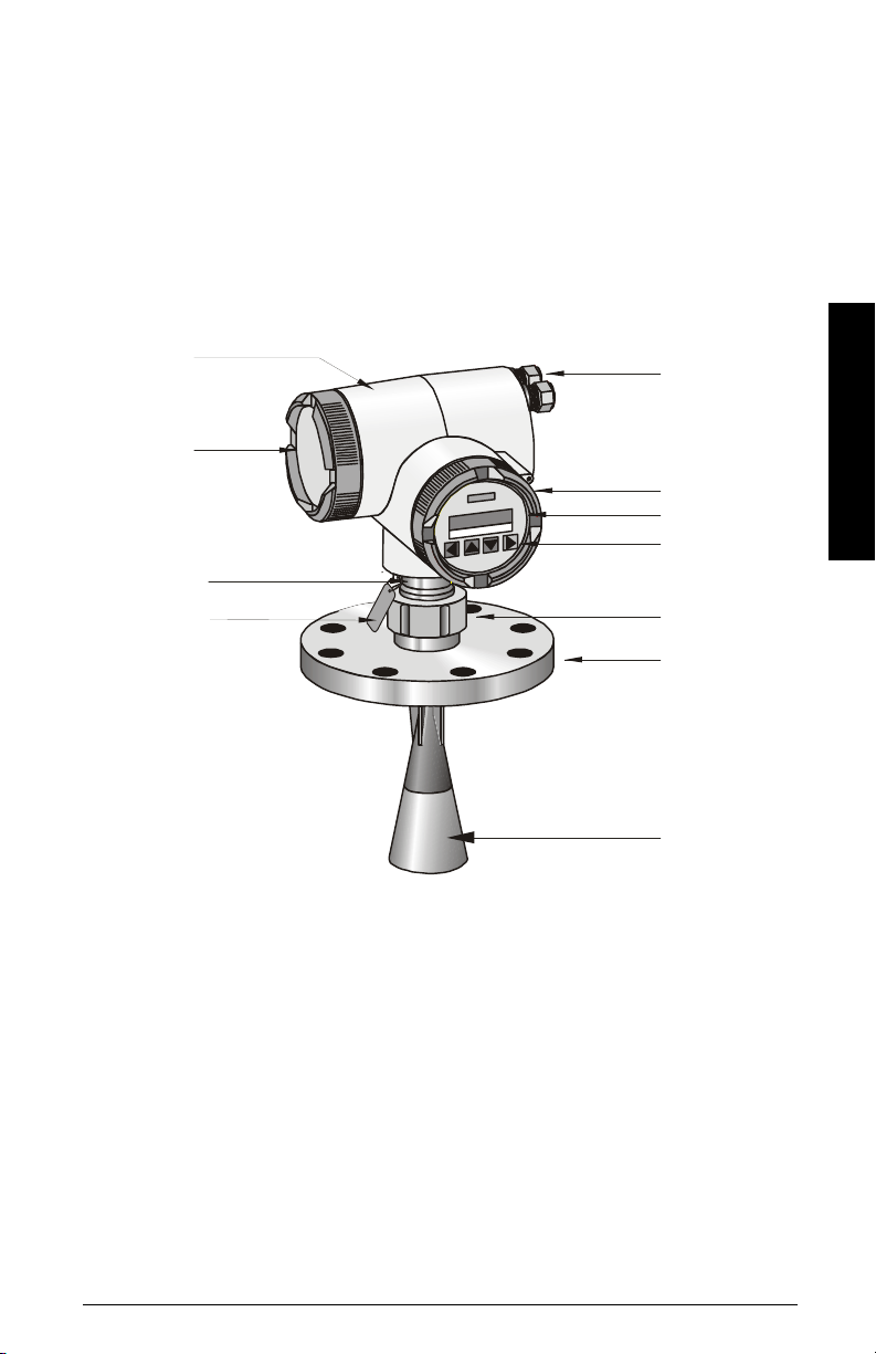
Enclosure
• construction Die-cast aluminum, painted
• conduit 2 x M20
or 2 x ½” NPT
• ingress protection Type 4X/NEMA 4X, Type 6/NEMA 6, IP 671
Environmental2
location: indoor/outdoor
altitude: 2000 m max
ambient temperature: -40 to 65°C (-40 to 149°F)
relative humidity: suitable for outdoor (Type / NEMA 4X, 6/ IP67)
installation category II
pollution degree 4
• Process Temperature -40 to 200°C (-40 to 392°F),optional -40 to 250°C
(-40 to 482°F)
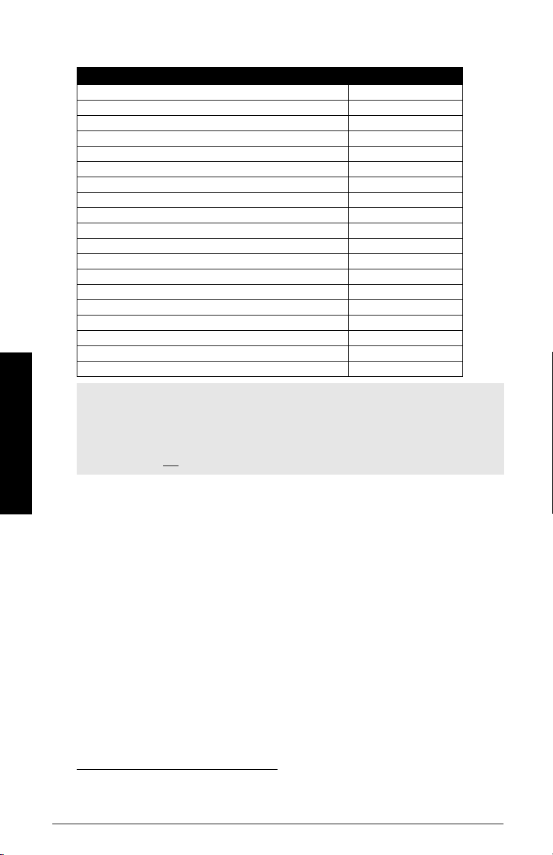
Process Connection Weight
Universal, 3" / 80 mm, flat faced, 0.5 bar maximum 10.9 kg (24 lbs)
Universal, 4" / 100 mm, flat faced, 0.5 bar maximum 12.7 kg (28 lbs)
Universal, 6" / 150 mm, flat faced, 0.5 bar maximum 15.0 kg (33 lbs)
DN80 PN16, flat faced 11.9 kg (26.1 lbs)
DN80 PN40, flat faced 12.9 kg (28.4 lbs)
DN100 PN16, flat faced 13.2 kg (28.9 lbs)
DN100 PN40, flat faced 15.5 kg (34.1 lbs)
DN150 PN16, flat faced 19.2 kg (42.1 lbs)
DN150 PN40, flat faced 24.1 kg (43.1 lbs)
3", 150 lb class, raised faced 12.2 kg (26.8 lbs)
3", 300 lb class, raised faced 14.3 kg (31.5 lbs)
4", 150 lb class, raised faced 14.8 kg (32.5 lbs)
4", 300 lb class, raised faced 20.2 kg (44.4 lbs)
6", 150 lb class, raised faced 20.1 kg (44.2 lbs)
6", 300 lb class, raised faced 31.8 kg (69.9 lbs)
JIS DN80 10K, flat faced 11.9 kg (26.1 lbs)
JIS DN100 10K, flat faced 13.2 kg (28.9 lbs)
JIS DN150 10K, flat faced 19.2 kg (42.1 lbs)
Easy Aimer 11.8 kg (26 lbs)
Note:Please ensure these are the most recent specifications. Contact your Siemens
Milltronics representative, or check our web site at www.siemens-milltronics.com for
the most up-to-date information.
WARNING: This product is designated as a Pressure Accessory per Directive
97/23/EC and is not intended for use as a safety device.
1. Use only approved, suitable sized hubs for watertight applications.
2. See Process/Ambient de-rating curves in Appendix III.

7ML19985FH03 SITRANS LR 400 – INSTRUCTION MANUAL Page 7
mmmmm
Specifications
• Electromagnetic compatibility
Spurious emission according to EN 50 081
Interference strength according to EN 50 082 and NAMUR
• Perm. ambient -40 to 65°C (-40 to 149°F) (non-hazardous version)
temperature -20 to 65°C (-4 to 149°F) (hazardous version)
LCD: -10 to 55 °C (14 to 131°F)
Observe the temperature classes in hazardous areas!
• Perm. storage -30 to 80°C (-22 to 176°F),
temperature
Communication
• Communication: HART
Load 230 to 600 Ω, 230 to 500 Ω when connecting a coupling
module
Line two-wire shielded: ≤3 km
multi-wire shielded: ≤1.5 km
Protocol HART, Version 5.1
Communication: Profibus-PA
Protocol Layer 1 and 2 Profibus-PA,
technology: IEC 61158-2, slave-functionality
Device Class A
Device Profile 3.0
• PC/Laptop requirements IBM-compatible
RAM ≥64 Mbytes
Hard disk ≥100 Mbytes
RS 232-C interface
VGA graphic card (≥640 x 480)
• Software for PC/Laptop Windows 95/98/2000 or NT 4.0
SIMATIC PDM
WARNING: Materials of construction are chosen based on their chemical
compatibility (or inertness) for general purposes. For exposure to specific
environments, check with chemical compatibility charts before installing.

Page 8 SITRANS LR 400 – INSTRUCTION MANUAL 7ML19985FH03
mmmmm
Specifications
Approvals (verify against device nameplate)
• Explosion Protection Certificate No. PTB 00 ATEX 1024
*Refer to device II 1/2G EEx d IIC T6II 2G EEx d IIC T6
nameplate II 1/2G EEx dem IIC T6II 2G EEx dem IIC T6
II 1/2G EEx dem [ib] IIC T6II 2G EEx dem [ib] IIC T6
II 1/2G EEx dem [ia] IIC T6II 2G EEx dem [ia] IIC T6
FM/CSA1Class I, Div. 1, Groups B, C, D; Class II/III, Div. 1,
Groups E, F, G
Certificate No. DMT 01 ATEX E 038
II 1/2 D IP 65 (dust zone 20, zone 21 approval)
• General CSAus/c, FM
• Radio FCC, Industry Canada, European Radio
1. CSA Hazardous approval is pending. See www.siemens-milltronics.com for
current listing.
WARNING: This product is designated as a Pressure Accessory per directive
97/23/EC and is not intended for use as a safety device.
Note:Please ensure these are the most recent specifications. Contact your Siemens
Milltronics representative, or check our web site at www.siemens-milltronics.com for
the most up-to-date information.

7ML19985FH03 SITRANS LR 400 – INSTRUCTION MANUAL Page 9
mmmmm
Specifications
Dimensions
SITRANS LR 400 (without Temperature Extension)
*Flange acc. to DIN 2527 / ANSI B16.5 / JIS B2238 bolt hole pattern
**A purging system installed between the flange and the horn antenna is an option for the
SITRANS LR 400. The system provides an inlet on the flange where cooling air or cleaning
fluid passes through the flange and exits the inside of the horn to clean it. The customer
will supply the purging medium by manual or automatic valve system. This option is only
available with universal flanges.
SITRANS LR
Note:Process temperature and pressure capabilities are dependent upon
information on the process device tag. See Appendix IV (Process Pressure/
Temperature de-Rating). Reference drawing listed on the tag is available upon
request.
WARNING: The user is responsible for the selection of bolting and gasket
materials which will fall within the limits of the flange and its intended use and
which are suitable for the service conditions.
204mm
(8.0")
281mm
(11.1")**
191mm
(7.5") 238mm
(9.4")
74 mm
(2.9")
93mm
(3.7")
horn
process
flange*
threaded
ring
intermediate
flange
electronics
cover
connection
cover
earth
terminal

Page 10 SITRANS LR 400 – INSTRUCTION MANUAL 7ML19985FH03
mmmmm
Specifications
SITRANS LR 400 with optional Temperature Extension
SITR AN S LR
process
flange*
*Flange acc. to DIN 2527 / ANSI B16.5 / JIS B2238 bolt hole pattern
Note: Process temperature and pressure capabilities are dependent upon
information on the process device tag. See Appendix IV (Process Pressure/
Temperature de-Rating). Reference drawing listed on the tag is available upon
request.
WARNING: The user is responsible for the selection of bolting and gasket
materials which will fall within the limits of the flange and its intended use and
which are suitable for the service conditions.
204mm
(8.0")
384mm
(15.1")
191 mm
(7.5")
238mm
(9.4")
74 mm
(2.9")
93mm
(3.7")
horn
threaded
ring
electronics
cover
connection
cover
intermediate
flange

7ML19985FH03 SITRANS LR 400 – INSTRUCTION MANUAL Page 11
mmmmm
Specifications
SITRANS LR 400 with optional Easy Aimer LR connection
WARNING: The user is responsible for the selection of bolting and gasket
materials which will fall within the limits of the flange and its intended use and
which are suitable for the service conditions.
SITRAN S LR
204mm
(8.0")
285 mm (11.2")
412 mm (16.2") with
temperature extension
threaded
ring
electronics
cover
connection
cover
Easy Aimer
Flange
horn
74 mm
(2.9")
93mm
(3.7")
188.2 mm
(7.4")
9.6 mm
(0.38")
intermediate
flange
235.2mm
(9.3")

Page 12 SITRANS LR 400 – INSTRUCTION MANUAL 7ML19985FH03
mmmmm
Specifications
DIN / JIS Flat Face Flange Diagram
Flange according to DIN 2527 (see Flange Diagram above)
Flange according to JIS B 2238
Pipe Size Flange
Size Flange
O.D. Thickness
(s) Bolt Hole
Circle Ø Bolt Hole
ØNumber of
Bolts
80 mm PN 16 200 mm 20.0 mm 160 mm 18.0 mm 8
100 mm PN16 220 mm 20.0 mm 180 mm 18.0 mm 8
150 mm PN 16 285 mm 22.0 mm 240 mm 22.0 mm 8
80 mm PN 40 200 mm 24.0 mm 160 mm 18.0 mm 8
100 mm PN 40 235 mm 24.0 mm 190 mm 22.0 mm 8
150 mm PN 40 300 mm 28.0 mm 250 mm 26.0 mm 8
Pipe Size Flange
Size Flange
O.D. Thickness
(s) Bolt Hole
Circle Ø Bolt Hole Ø Number of
Bolts
80 mm 10 K 185 mm 20.0 mm 150 mm 19.0 mm 8
100 mm 10 K 210 mm 22.0 mm 175 mm 19.0 mm 8
150 mm 10 k 280 mm 24.0 mm 240 mm 23.0 mm 8
Note: Process temperature and pressure capabilities are dependent upon
information on the process device tag. See Appendix IV (Process Pressure/
Temperature de-Rating). Reference drawing listed on the tag is available upon
request.
WARNING: The user is responsible for the selection of bolting and gasket
materials which will fall within the limits of the flange and its intended use and
which are suitable for the service conditions.
bolt hole
Ø
thickness (s)
flange O.D.
bolt hole circle Ø
horn mounting holes

7ML19985FH03 SITRANS LR 400 – INSTRUCTION MANUAL Page 13
mmmmm
Specifications
ANSI Raised Face Flange Diagram
Flange according to ANSI B 16.5 (see Flange Diagram above)
Pipe
Size Flange
Size Flange
O.D. Thickness
(s) Face
O.D. Bolt Hole
Circle Ø Bolt
Hole Ø Number
of Bolts
3" 150 # 7.50" 0.941" 5.0" 6.00" 0.75" 4
4" 150 # 9.00" 0.941" 6.19" 7.50" 075" 8
6" 150 # 11.00" 1.00" 8.5" 9.50" 0.88" 8
3" 300 # 8.25" 1.12" 5.0" 6.62 0.88" 8
4" 300 # 10.00" 1.25" 6.19" 7.88" 0.88" 8
6" 300 # 12.51" 1.44" 8.5" 10.62" 0.88" 12
Note: Process temperature and pressure capabilities are dependent upon
information on the process device tag. See Appendix IV (Process Pressure/
Temperature de-Rating). Reference drawing listed on the tag is available upon
request.
WARNING: The user is responsible for the selection of bolting and gasket
materials which will fall within the limits of the flange and its intended use and
which are suitable for the service conditions.
thickness (s)
raised face thickness
0.063" (mm)
bolt hole Ø
horn mounting holes
flange O.D.
bolt hole circle Ø
face O.D.

Page 14 SITRANS LR 400 – INSTRUCTION MANUAL 7ML19985FH03
mmmmm
Specifications
Universal Slotted Flange Diagram
Flangeaccording to Universal Slotted Flange (see Flange Diagram above)
Pipe
Size Flange
O.D. Thick-
ness (s) Bolt Hole
Circle Max Ø Bolt Hole
Circle Min Ø BoltHole
radius Number of
Slotted Holes
3" or 80 mm 7.87" 0.40" 6.30" 5.90" 0.38" 8
4" or 100 mm 9.00" 0.40" 7.50" 6.89" 0.38" 8
6" or 150 mm 11.22" 0.40" 9.50" 9.44" 0.45" 8
8" or 200 mm 13.5" 0.40" 11.75" 11.4" 0.45" 12
WARNING: The user is responsible for the selection of bolting and gasket
materials which will fall within the limits of the flange and its intended use and
which are suitable for the service conditions.
45°
flange O.D.
section A-A
thickness
only available on pipe
size 8" (200 mm)
number of
slotted bolt
holes
Bolt hole
circle min Ø
Bolt hole
circle max Ø
AA

7ML19985FH03 SITRANS LR 400 – INSTRUCTION MANUAL Page 15
mmmmm
Specifications
Easy Aimer LR Flange Connection
clamping screw - 3 places
mounting hole - 3 places, to
suit M8 or 3/8" bolt holes,
120° apart, ø 7/16" (11 mm)
on ø 6.2" (157 mm)
ø 177.8 mm (7")

Page 16 SITRANS LR 400 – INSTRUCTION MANUAL 7ML19985FH03
mmmmm
Installation
Installation
Mounting Location
• Do not mount in direct sunlight without the use of a sun shield. Refer to Appendix III
(Ambient/Operating Temperature Specification) on page 78.
• Mount the unit more than 1 m away from the vessel walls, pipes and other
assemblies as well as the filling stream, because all these influences will become
noticeable as reflective interference. Align the antenna so that the radar cone
intersects the surface of the measuring medium as vertically as possible
• When mounting the SITRANS LR 400 in outdoor applications, always set Parameter
5.2 Customer Code to prevent unwanted resetting of parameters.
Notes:
• The SITRANS LR 400 is rated for Type 4X/NEMA 4X, Type 6/NEMA 6, IP
67. Follow all installation and operating instructions to meet the
requirements of this type of protection. Use only approved, suitable
sized hubs for watertight applications.
• Observe all maximum permissible ambient and process temperatures.
Refer to Appendix III (Ambient/Operating Temperature Specification).
Provide a warning sign and/or touch guard if the surface of the measuring
instrument can become hotter than 70°C in use.
WARNINGS:
• This product is designated as a Pressure Accessory per directive
97/23/EC and is not intended for use as a safety device.
• Improper installation may result in loss of process pressure.
WARNING: Forvessels withconical orparabolic tops,avoidmounting
the unit at the center. The concavity of the top can focus echoes into the
centre, giving false readings.
Flat
P a ra b o lic
Parabolic or Conical Flat
is preferred
location
is acceptable
location
Easy Aimer
Other manuals for SITRANS LR 400
6
Table of contents
Other Siemens Laser Level manuals