Siemens VIS3I-328 User manual

Building Technologies
Fire Safety & Security Products
VIS3I-328
Visilynx 3
Integrated System Unit
Installation Manual

Data and design subject to change without notice. / Supply subject to availability.
© 2008 Copyright by Siemens Building Technologies
We reserve all rights in this document and in the subject thereof. By acceptance of the document the recipient acknowledges these rights
and undertakes not to publish the document nor the subject thereof in full or in part, nor to make them available to any third party without our
prior express written authorisation, nor to use it for any purpose other than for which it was delivered to him.

3
Siemens Building Technologies
Fire Safety & Security Products 10.2008
Contents
1Safety .......................................................................................................5
1.1 Target group..............................................................................................5
1.2 General safety precautions .......................................................................5
1.3 Meaning of the signal words .....................................................................6
1.4 Meaning of the hazard symbols ................................................................6
2Standards and guidelines ......................................................................6
3Technical data .........................................................................................7
3.1 Specifications ............................................................................................7
3.2 Mechanical dimensions.............................................................................8
4Details for ordering.................................................................................9
5Scope of delivery ....................................................................................9
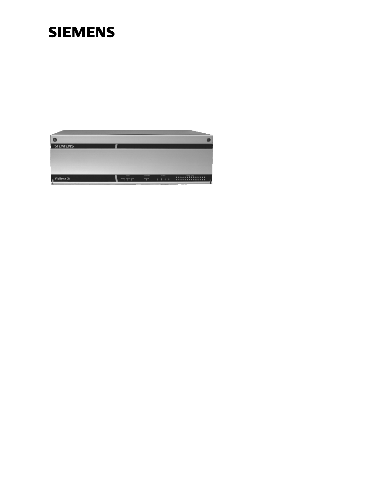
6Description of equipment.....................................................................10
6.1 Enclosure ................................................................................................11
6.2 Printed circuit boards (PCBs)..................................................................12
6.3 Power supply module VIS3I-PSU ...........................................................13
6.4 Cooling fan ..............................................................................................14
6.5 Front panel indicators .............................................................................15
6.6 Rear panel connections and controls......................................................16
6.7 Firmware and software ...........................................................................19
6.8 Quad card VIS3-QUAD...........................................................................20
7Installation .............................................................................................21
7.1 Installing option cards .............................................................................21
7.2 Connecting two VIS3I-328 units for expansion.......................................22
8Commissioning .....................................................................................23
8.1 Inspect all items ......................................................................................23
8.2 Connect a PC running VisiPC software ..................................................23
8.3 Set VisiPC default product to integrated.................................................24
8.4 Connect and power up the VIS3I-328s ...................................................24
8.5 Confirm software versions ......................................................................25
8.6 Set clock time and perform VisiPC self-test............................................25
8.6.1 Set clock time..........................................................................................25
8.6.2 VisiPC tester and simulator.....................................................................25
8.6.3 VisiPC self-test........................................................................................26
8.7 Load new configuration as necessary ....................................................27
8.8 Load Asian display font data...................................................................27
9System integration................................................................................28
9.1 Connecting VK-3 keyboards ...................................................................28
9.2 Connecting CKA Keyboards ...................................................................29
9.3 Connecting alarm inputs .........................................................................31
9.4 Connecting a VCR/DVR and multiplexer ................................................32
9.5 Connecting a quad card output to a video input .....................................34
9.6 Distributed video switching using a VisiWire or PCCON network ..........35
9.6.1 Setting the node address ........................................................................35
9.6.2 Determining how VIS3I-328 unit nodes can be networked.....................36
9.6.3 Connecting VIS3I-328 unit nodes using trunk connections ....................36
9.6.4 Configuring network alarms ....................................................................39
9.6.5 Connecting VIS3I-328 to Visilynx 2 nodes using PCCON......................40
9.6.6 Controlling 256 cameras x 64 monitors (banked switching; not full
cross point)..............................................................................................42

4
Siemens Building Technologies
Fire Safety & Security Products 10.2008
9.6.7 Controlling 64 cameras x 64 monitors (full cross point)..........................44
9.7 Controlling via the Video Management Software IVM ............................45
9.8 Clock Synchronisation.............................................................................45
10 Maintenance and service......................................................................46
10.1 Routine maintenance ..............................................................................46
10.2 Corrective maintenance ..........................................................................46
10.2.1 Policy.......................................................................................................46
10.2.2 Line replaceable units (LRUs).................................................................46
10.2.3 Fault indications ......................................................................................47
10.3 System fault-finding process ...................................................................48
10.3.1 Initial checks............................................................................................48
10.3.2 Diagnostic tool.........................................................................................48
10.3.3 Self-test alarms .......................................................................................49
10.3.4 VisiPC self-tests ......................................................................................50
11 Disposal .................................................................................................55

5
Siemens Building Technologies
Fire Safety & Security Products 10.2008
1 Safety
1.1 Target group
The instructions in this document are designed only for the following target group:
Target readers Qualification Activity Condition of the
product
Installer Technical training for
building or electrical
installations.
Assembles/installs the
product, individual
components of the
product or replacement
parts.
Components of the
product are not yet
assembled/installed or
need to be replaced.
1.2 General safety precautions
zRead the general safety precautions before installing the device.
zFollow all warnings and instructions marked on the device.
zKeep this document for reference.
zAlways pass this document on together with the product.
zIt is recommended that all preparatory work (e.g. fitting of accessories) be
carried out in a workshop prior to final installation.
Liability claim
zDo not connect the device if it is damaged or any parts are missing.
zDo not make any changes or modifications to the device unless they are
expressly mentioned in this manual and have been approved by the
manufacturer.
zUse only spare parts and accessories that have been approved by the
manufacturer.
Danger of electrical shock due to incorrect connection
zUse the device only in conjunction with a power supply cable that has been
approved in your country and complies with the national standards.

6
Siemens Building Technologies
Fire Safety & Security Products 10.2008
1.3 Meaning of the signal words
The severity of a hazard is indicated by the following written warning notices.
Signal word Type of hazard
CAUTION There is a risk of minor to medium injuries or damage to property
IMPORTANT Malfunctioning may result
1.4 Meaning of the hazard symbols
The nature of the hazard is indicated by icons.
Warning of a hazard
2 Standards and guidelines
The product meets the requirements of the following EU Directives. The EU
declaration of conformity is available from:
Siemens Building Technologies
Fire & Security Products GmbH & Co. oHG
76181 Karlsruhe
Germany
EU Directive 2004/108/EC on electromagnetic compatibility
Conformity with the European Directive 2004/108/EC is demonstrated by
compliance with the following standards:
Emitted interference: EN 61000-6-3
EN 55022 Class B
Resistance to interference: EN 50130-4
EU Directive 2006/95/EC “Low-Voltage Directive”
Compliance with the European Directive 2006/95/EC has been proven by testing
according to the following standard:
Safety: EN 60950-1

7
Siemens Building Technologies
Fire Safety & Security Products 10.2008
3 Technical data
3.1 Specifications
Single VIS3I-328 Expanded VIS3I-328 Pair
Video Connections
Input connectors 32 BNC 64 BNC
Input level 0.7 – 1.5 Vpp
Input impedance 75 Ohm
Loop-through connectors 32 BNC 64 BNC
Output connectors 8 BNC 16 BNC
Output impedance 75 Ohm
Video Performance (nominal)
Frequency response (-3 dB point) > 5 MHz
Chrominance delay < 15 nsec < 18 nsec
Chrominance gain > 97 % > 91 %
K-rating (2T pulse/bar) < 2.2 % < 4.0 %
Signal to noise (567 weighted) > 70 dB > 70 dB
Signal to noise (567 unweighted) > 60 dB > 60 dB
Crosstalk (at 4.43 MHz, input to input) -36 dB -27 dB
Video Matrix
Single unit 32 i/p ×8 o/p 64 i/p ×16 o/p
Text Insertion
Text columns per output channel 38 chars.
Text rows per output channel 14 chars.
Telemetry Channels
C-type channels 32 64
C-type carrier frequency 11.3 MHz
D-type channels 32 64
D-type fixed termination per channel 120 Ohm
Serial Ports
RS-232 control ports 1 2
Dual standard RS-422/232 control ports 3 6
RS-422/485 keyboard ports 1
Keyboards powered from keyboard port 1
Serial port fixed RS422/RS485 termination 120 Ohm
Other Connections
Alarm inputs via alarm connector panel 128 channels 256 channels
Relay outputs 4 SPDT 8 SPDT
Relay contacts max voltage 12 V DC
Relay contacts max current 1 A DC

8
Siemens Building Technologies
Fire Safety & Security Products 10.2008
Single VIS3I-328 Expanded VIS3I-328 Pair
Internal Option Cards
V3-QUAD: quad card with independent BNC o/p 0 – 2 0 – 4
Power Input
Voltage 110 – 230 V AC
Frequency 50/60 Hz
Power consumption 2 A 4 A
Physical – Unit
Height in rack units 3 U 6 U
Extra height of mounting feet 7 mm 14 mm
Extra width of rack mount brackets 50 mm
Weight 8.8 kg 17.6 kg
Physical – Package
Dimensions (W ×H ×D) 560 ×275 ×550 mm –
Total weight 12.7 kg –
Storage Conditions
Temperature -10 to +70 °C
Operating Conditions
Temperature 0 – 40 °C
Humidity (non-condensing) 10 – 90 %
3.2 Mechanical dimensions
3
2
1
4
5
6
78 9
Fig. 1 Mechanical dimensions
1 352 mm 6 432 mm
2 365 mm 7 57 mm
3 356 mm 8 132 mm (264 mm for expanded VIS3I-328 Pair)
4 481 mm 9 140 mm
5 465 mm

9
Siemens Building Technologies
Fire Safety & Security Products 10.2008
4 Details for ordering
Type Order No. Designation Weight
VIS3I-328 S54567-C750-A1 VIS3I-328 System Unit 8.80 kg
VIS3I-PSU S54567-B758 VIS3I-PSU with output connector lead attached 0.38 kg
VIS3-QUAD S54567-B753-A1 VIS3 Colour Quad Card 0.30 kg
VIS3-ALARMBOX S54567-F759 Visilynx 3 Alarm Panel 1.00 kg
V3-K S54561-C790 V3 Keyboard 4.00 kg
VIS3-ALMCAB S54567-K757 Visilynx 3 Alarm Cable 0.30 kg
VIS3-CONF S54567-K754 Visilynx 3 Configuration Cable 0.20 kg
VIS3I-EXP S54567-K755 Visilynx 3i Expansion Cable 0.30 kg
VIS3-KEYCAB S54567-K756 Visilynx 3 Keyboard Cable 0.20 kg
VIS3-PCCONCAB S54567-K752 Visilynx 3 PCCON Cable 0.20 kg
5 Scope of delivery
z1 x VIS3I-328 System Unit
z2 x Rack Mount Brackets
z1 x Mains Lead, UK (Located in packaging)
z1 x Mains Lead, European (Located in packaging)
z1 x Data Cable for PC Configuration (Located in packaging)
z1 x Installation Instruction
z1 x CD for VisiPC Software & Installation Manual
z8 x Screw Terminal Plug for Telemetry, 12 Way (Located in bag)
z2 x Screw Terminal Plug for relays, 6 Way (Located in bag)
NOTE
The complete assembly should be mounted and tested in the workshop prior to use on-site.
Accessories
zFlat blade screwdriver, 2.5 mm blade width.
zPhillips No. 1 screwdriver.
z2.5 mm A/F (across flats) Allen key.

10
Siemens Building Technologies
Fire Safety & Security Products 10.2008
6 Description of equipment
The Visilynx 3i (VIS3I-328) is a 32 loop-through input by 8-output full cross-point
video matrix node contained in a 19” wide by 3U high enclosure.
You can connect two identical units together using an expansion cable to double
the size of the video matrix to 64 loop-through input by 16-output full cross-point
switcher. In this configuration, you set one of the two units to be the Master and
this can connect to a Visilynx control network, and you set the other to be the Slave
unit.
You can connect up to 127 nodes together to form a distributed video switching
network. The video connections between nodes are made by trunk connections.
In a networked system, a keyboard at one node may view and control cameras,
VCR/DVRs and multiplexers at any other node. It may also respond to alarms from
other nodes. The number of video inputs from remote nodes that can be viewed at
any one time is governed by the number of available trunk connections between
the nodes.
You can expand any VIS3I-328, by fitting up to two optional Visilynx 3 quad cards
(Type VIS3-QUAD). In a single VIS3I-328 with 8 monitor outputs, each quad card
makes available the equivalent of an additional 4 monitor outputs.
The main user interface device of the VIS3I-328 system is the Visilynx 3 keyboard.
A single keyboard may be powered by a single VIS3I-328, and a further 15
keyboards with local power supplies may be addressed. You must not connect a
keyboard to both power sources at once.
Each VIS3I-328 is designed to be used free standing (as supplied) or fitted into a
standard 19” rack cabinet.
The VIS3I-328 is supplied with configuration and test software called VisiPC, which
you should install onto a suitable PC. This forms the heart of the system's
configuration and test capability.
This manual is designed to cover basic operation. To be able to understand and
use advanced features such as networking it is recommended to attend a product
training course.
General
The VIS3I-328 is made up of these mechanical and electrical subsystems:
zEnclosure (see chapter 6.1 Enclosure)
zPrinted Circuit Boards (see chapter 6.2 Printed circuit boards (PCBs)).
zPower Supply Module (see chapter 6.3 Power supply module VIS3I-PSU)
zCooling fan (see chapter 6.4 Cooling fan)
zFront panel indicators (see chapter 6.5 Front panel indicators)
zRear panel connections and controls (see chapter 6.6 Rear panel connections
and controls)
zFirmware and software (see chapter 6.7 Firmware and software)
zQuad cards (see chapter 6.8 Quad card VIS3-QUAD)

11
Siemens Building Technologies
Fire Safety & Security Products 10.2008
6.1 Enclosure
Fig. 2 VIS3I-328 enclosure
The VIS3I-328 enclosure comprises four main parts:
zBase assembly
zCover
zFront panel
zRack mount brackets (optional)
The base assembly is fabricated from 1.2 mm zintec sheet with a natural finish. It
provides fasteners for mounting the cooling fan and the control card. Cut-outs are
provided on the rear panel for the mounting the input/output connectors (see
chapter 6.6 Rear panel connections and controls). Details of the connectors are
screen printed on the rear panel. Two additional cut outs are provided in the sides
of the base assembly to provide a path for the cooling air. Four black Polyastomer
feet are fitted in the base of the assembly.
The cover is fabricated from 1.2 mm Zintec Sheet and finished with polyester
powdercoat. The cover is fastened to the base using a slide-in capture bracket and
eight M4 screws. Vent holes are provided in the sides and the cover incorporates
an earth stud.
The hinged front panel has two cross-head captive screws which are provided for
fastening the panel to the base assembly. Holes are included in the panel for
viewing the indicators (see chapter 6.5 Front panel indicators).
The rack mount brackets are manufactured from 3.0 mm aluminium sheet with a
brushed finish and are optionally fitted to the base assembly for mounting the unit
into a 19” rack enclosure.

12
Siemens Building Technologies
Fire Safety & Security Products 10.2008
6.2 Printed circuit boards (PCBs)
The VIS3I-328 contains four printed circuit boards (PCBs) to provide control,
configuration, access to the input/output connectors and interfacing to the two
option cards. The PCBs are:
1 Control PCB
2 BNC Connector PCB
3 D Connector PCB
4 Slot Expansion PCB
The PCBs are fixed within the unit enclosure and are therefore not considered to
be user serviceable parts. Fig. 3 shows the location of the PCBs within the unit.
1
3
42
Fig. 3 Printed circuit boards

13
Siemens Building Technologies
Fire Safety & Security Products 10.2008
6.3 Power supply module VIS3I-PSU
Fig. 4 Power supply module (VIS3I-PSU)
Purpose
A proprietary universal AC mains input, bipolar DC output switch mode power
supply fixed on a mounting tray (shown above) for ease of replacement (see
chapter 4 Details for ordering).
NOTE
For information on the replacement and the specifications of the power supply module please refer to
the installation instruction for VIS3I-PSU.
Specification
Input 100 – 240 V AC, 47 – 63 Hz
Output +5.2 V DC / 8.5 A
-5.2 V DC / 4 A
Line regulation ± 0.5 %
Ripple and noise ± 1.0 % max
Dimensions (L x W x H) 127.0 ×81.3 ×38.1 mm

14
Siemens Building Technologies
Fire Safety & Security Products 10.2008
6.4 Cooling fan
Fig. 5 Cooling fan
Purpose
A fixed speed DC fan that forces air through the enclosure intake vent, across the
PCBs and power supply, and out of the exhaust vent.
Specification
Input 12 V DC
Dimensions (L ×W×H) 80 x 80 x 25 mm

15
Siemens Building Technologies
Fire Safety & Security Products 10.2008
6.5 Front panel indicators
The VIS3I-328 unit has 40 single colour LED indicators on the front panel.
The LEDs are located in 4 distinct groups:
Indicator Group Number of LED
Mode 3
Network 1
Relays 4
Video Loss 32
Fig. 6 Front panel indicators
Indicator
Group
Name Description Colour On Flashing Off
MODE Master Master Mode Blue Unit is Master Two Masters are connected Unit is Slave
Status General
Status
Red Hardware failure
or configuration
error
Slow Flash: self-test failure
Fast Flash: waiting for
another VisiPC software
component
All software
components are loaded
and self-tests have
passed. Main controller
software is running
Slave Slave Mode Blue Unit is Slave No Master is connected Unit is Master
NETWORK VisiWire Green Blinks when valid data is
received. Blinks at 1Hz in
VIS3I-328 Bridge mode.
RELAYS 1 - 4 Yellow Relay active Relay inactive
VIDEO
LOSS
1 - 32 Video Loss
Channel 1-32
Yellow No video syncs
on channel
Syncs ok, but picture level is
low
Video signal ok on
channel

16
Siemens Building Technologies
Fire Safety & Security Products 10.2008
6.6 Rear panel connections and controls
You make all external connections to the VIS3I-328 via the rear panel. The
connections are divided into these distinct groups:
Fig. 7 Rear panel connectors and controls
1 Video Inputs
2 Video loop-throughs
3 Video Outputs
4 D-type Telemetry
5 Quad Outputs
6 Video & Control Expansion
7 Serial Ports
8 Alarm Inputs
9 Relay Outputs
10 Mains Input
Name Description Type Conductor
Number
Conductor Function Serial Port
Inner SignalInput 1–32 Video Control Input
Channel 1 – 32
BNC Female
Outer Ground
Inner SignalLoop 1–32 Video Loop-Through
Channel 1 – 32
BNC Female
Outer Ground
1 NC
2 TX (RS-232)
3 RX (RS-232)
4 TX- (RS-422)
5 RX- (RS-422)
6 GND
7 GND
8 TX+ (RS-422)
9 RX+ (RS-422)
Serial 1 General purpose serial port
(RS-232/422, reconfigurable)
9-way D-Type
Female
Shield GND
1
(16)
Serial 3 General purpose serial port
(RS-232/422, reconfigurable)
9-way D-Type
Female
1 – 9 As Serial 1 3
(18)
Serial 4 General purpose serial port
(RS-232/422, reconfigurable)
9-way D-type
Female
1 – 9 As Serial 1 4
(19)

17
Siemens Building Technologies
Fire Safety & Security Products 10.2008
Name Description Type Conductor
Number
Conductor Function Serial Port
1 DCD
2 RX
3 TX
4 DTR
5 GND
6 DSR
7 RTS
8 CTS
9 RI
PCCON Remote Control
(RS-232, reconfigurable)
9-way D-Type
Male
Shield GND
2
(17)
1 NC
2 TX
3 RX
4 NC
5 GND
6 NC
7 NC
8 NC
9 NC
Test/Config Test and Configuration Port
(RS-232, reconfigurable)
9-way D-Type
Female
Shield GND
9
1 +12 V
2 +12 V
3 NC
4 TX-
5 RX-, DATA_485-
6 GND
7 GND
8 TX+
9 RX+, DATA_485+
Keyboard Keyboard Control Port
(RS-422/485)
9-way D-Type
Female
Shield GND
10
Inner SignalOutput 1–8 Video Output Channel 1 – 8 BNC female
Outer Ground
Left DATA+
Centre DATA-
Telemetry
1 – 32
D-Type Telemetry Sets of 3 screw
terminals
Right GND
Left NO
Centre COM
Relay 1 – 4 Relay Output 1 – 4 2×12 plug-in
screw terminal
Right NC
Inner SignalQuad A-B Quad Composite Video Out A-B
Only used by option card, if fitted
BNC Female
Outer Ground
1 GND
2 GND
3 Y
Quad A-B Quad S-Video Out A-B
Only used by option card, if fitted
4-pin MiniDIN
Female
4 C

18
Siemens Building Technologies
Fire Safety & Security Products 10.2008
Name Description Type Conductor
Number
Conductor Function Serial Port
1 Alm_return0
2 Alm_return1
3 Alm_return2
4 Alm_return3
5 Alm_return4
6 Alm_return5
7 Alm_return6
8 Alm_return7
9 Alm_return8
10 Alm_return9
11 Alm_return10
12 Alm_return11
13 Alm_return12
14 Alm_return13
15 Alm_return14
16 Alm_return15
17 NC
18 NC
19 NC
20 Alm_scan0
21 Alm_scan1
22 Alm_scan2
23 Alm_scan3
24 Alm_scan4
25 Alm_scan5
26 Alm_scan6
27 Alm_scan7
28 NC
29 GND
30 GND
31 GND
32 GND
33 GND
34 GND
35 GND
36 GND
37 GND
Alarms Alarms In from Alarm Panel 37-way D-Type
Female
Shield GND
Live Live
Earth Earth
Mains Power In 3 -way IEC inlet
Female
Neutral Neutral
Tab. 1 Rear panel connectors
NOTE
Serial port identification for a Slave expansion Unit is identified in parentheses (…).
Name Description Type Positions
Left position is SlaveSlave/Master Master/Slave Switch Slide switch
Right position is Master
Reset Processor reset Momentary push Push and release to reset the processor
Left switch is hex address Sixteen’sNetwork Address Address of node on network Rotary hex
Right switch is hex address Units
Tab. 2 Rear panel controls

19
Siemens Building Technologies
Fire Safety & Security Products 10.2008
6.7 Firmware and software
Tab. 3 shows firmware and software compatibility between VIS3I-328 and Visilynx
3 Modular. More up-to-date details are available in the latest Visilynx 3 Software
Release Notes.
Part Number Description How Loaded Version Compatibility
SW218 Keyboard software EPROM 5, 6 or later
(See below)
VIS3I-328 and V3 Modular
SW220 Main Controller software VisiPC 2.05 or later VIS3I-328 and V3 Modular
SW221 Flash Boot Loader software VisiPC 2.04 or later VIS3I-328 and V3 Modular
SW224 VisiPC software Installed on PC 2.01.0006 or
later
VIS3I-328 and V3 Modular
SW249 VIS3I-328 FPGA Firmware VisiPC 1.0 or later VIS3I-328 Only
SW250 VIS3I-328 European display
font data
VisiPC 1.0 or later VIS3I-328 Only
SW251 VIS3I-328 European and
Asian display font data
VisiPC 2.0 or later VIS3I-328 Only
Tab. 3 Firmware and software
Keyboard compatibility
VIS3I-328 is compatible with earlier Visilynx 3 keyboards that show SW218-5 on
their LCD when switched on. However, VIS3I-328 systems using these keyboards
should not enable camera bi-directional telemetry alarms 1190 to 1701 for
keyboard access. These alarms cannot then be handled by PCCON either, but
VisiPC will show their true states.
IMPORTANT
These earlier keyboards cannot correctly determine whether they are supposed
to respond to these higher alarm numbers, and may show these alarms on their
alarm menus when they are not supposed to, or vice versa.
To disable these alarms for keyboard access:
1. Start VisiPC in the Visilynx3 Configurator sub-program as described in the
VisiPC Software Manual.
2. Select the Alarm Settings menu screen.
3. For each Alarm, ID 1190 onwards, ensure that None is selected in the Type
drop down menu.
4. Save the configuration and transfer the file to VIS3I-328.
NOTE
To be able to handle camera bi-directional telemetry alarms 1190 onwards at keyboards and when
using PCCON, make sure you are using keyboards that show SW218-6 or higher on their LCD when
switched on. Response options other than None can then be selected in the Type drop down menu at
the Visilynx3 Configurator sub-program Alarm Settings menu screen for these Alarm IDs.

20
Siemens Building Technologies
Fire Safety & Security Products 10.2008
6.8 Quad card VIS3-QUAD
CAUTION Only service personnel should open the VIS3I-328, after first disconnecting the
mains power supply.
Fig. 8 Quad card (VIS3-QUAD)
Purpose
Displays four pictures on a single video output in real time, with each segment
controllable as a separate monitor number (see chapter 4 Details for ordering).
Installation in unit
zOne or two cards may be fitted.
zIf only one card is fitted, it may occupy either of the internal option card slots.
zThe output connectors on the rear panel are in the same position when viewed
from above as the cards they serve.
zSee chapter 7 Installation.
Specification
zAccepts PAL color or CCIR monochrome cameras
z24 bit color digital video
z50 fields/sec display with 768 ×625 pixel resolution (PAL)
z1 multi-segment output that displays the four inputs in quad format in a specified
order, or any one input as full-screen
zEach segment can be independently frozen
z16 – 4 multiplexer on the inputs allows the quad to pick up any four of the
available monitor outputs
zSeparate composite and S-Video outputs, available on the rear panel
zTime base correction of video inputs ensures high quality pictures without the
need for external camera synchronization
zEach picture segment is frozen when the input source is switched, in both full
screen and quad mode, to prevent picture roll
zAll the video inputs have AGC to preserve clear images independent of
differences in input levels
zColor text insertion on the monitor output, with texts supplied by the control card
zDedicated self-test failure alarm per card.
This manual suits for next models
1
Table of contents