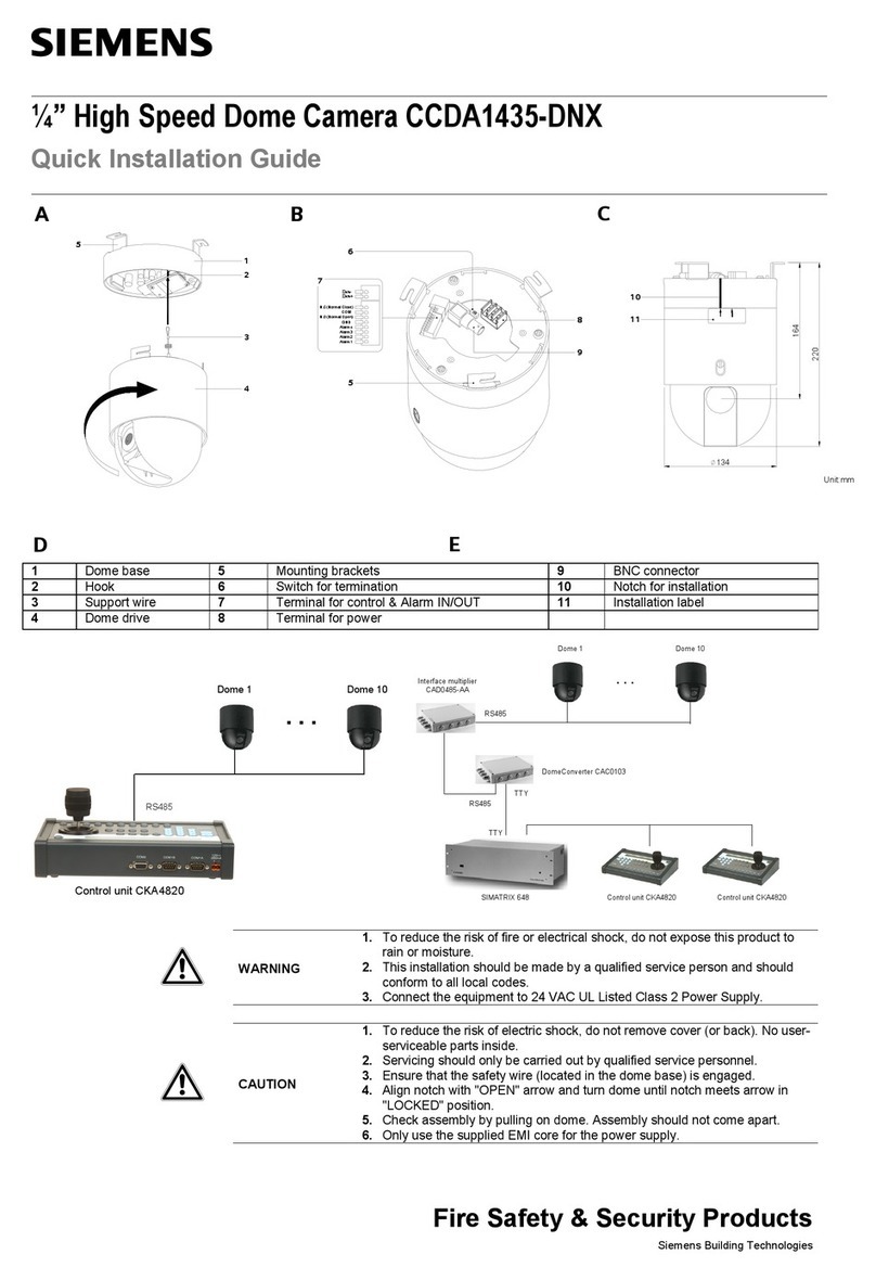
manuals.online logo
Brands
  1. Home
  2. •
  3. Brands
  4. •
  5. Siemens
  6. •
  7. Security Camera
  8. •
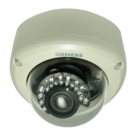
  9. Siemens CVWC1325-LX User manual

Siemens CVWC1325-LX User manual

Building Technologies
Fire Safety & Security Products
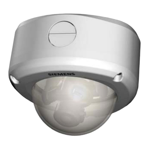
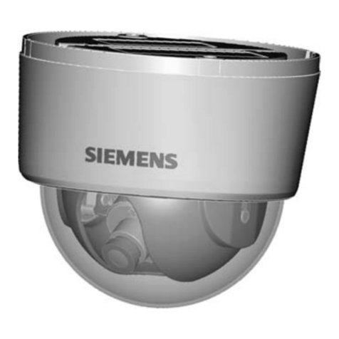
CVWC1325-LX
Vandalismusgeschützte 1/3“-CMOS-
Dome-Farbkamera mit Vario-Objektiv
und Ultrawide Dynamic Range
Installationsanleitung
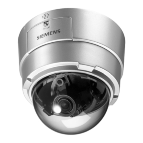
CVWC1325-LX
1/3“ CMOS Ultra Wide Dynamic Colour
Vandal Resistant Varifocal Dome
Installation Instruction
9
10
18
19
17
22
21
20
6
7
8
9
10
140 mm
112 mm
1
2
3
5
4
11
12
13
14 16
15
1 Alarmleitung (orange/gelb/rot/schwarz) Alarm cable (orange/yellow/red/black)
2 Zweidrahtleitung (blau/schwarz) Twisted pair cable (blue/black)
3 RS485-Kabel (braun/schwarz) RS485 cable (brown/black)
4 Netzkabel Power supply cable
5 Videoausgangs (BNC-Anschluss) Video output (BNC connector)
6 Kabeleintrittsöffnungen
Cable
entry
holes
7 Sockel
Base unit
8 Dome-Kuppel Dome hemisphere
9 Zoomhebel/Fixierschraube
Zoom
lever/locking
screw
10 Fokushebel/Fixierschraube
Focus lever/locking
screw
11 Monitorausgang Monitor output
12 CN1-Anschluss CN1 connector
13 CN2-Anschluss CN2 connector
14 RS485-Terminierungsschalter RS485 termination switch
15 Montageloch Unitmounting hole
16 OSD-Joystick (zum Öffnen des Bildschirmmenüs) OSDjoystick(on-screenmenu access)
17 Verschlussschraube für Kabelzuführung
Conduit
hole
plug
screw
18 Kameraeinstellvorrichtung Cameraadjustmentbracket
19 Achseneinstellung
Axis adjustment
20 Inneneinsatz Inner liner
21 Sicherheitsschrauben Securityscrews
22 Schraubendreher
Security
screwdriver
2
Siemens Building Technologies
Fire Safety & Security Products 10.2008
Lieferumfang
zDome-Kamera
z1 Servicemonitorkabel
zRemote-Software-CD
z2 Befestigungsschrauben
z2 Dübel
zMontageschablone
zInstallations- und Bedienungsanleitung (dieses Dokument)
zSchraubendreher
zRohranschlussadapter
zRohrverbindung
Package contents
zDome camera
z1 service monitor cable
zRemote software CD
z2 fixing screws
z2 wall plugs
zFixing template
zInstallation and operating instructions (this document)
zScrewdriver
zPipe adapter
zPipe joint
Sicherheit
Um die Gefahr eines Feuers oder Elektroschocks zu vermeiden,
darf dieses Gerät weder Regen noch Feuchtigkeit ausgesetzt
werden.
Die Installation sollte von einem qualifizierten Servicetechniker
gemäß den geltenden Vorschriften ausgeführt werden.
Schließen Sie das Gerät an ein Netzteil mit 12 V Gleichstrom oder
24 V Wechselstrom (UL Klasse 2) an. Der Warnhinweis oben ist an
der Kuppel angebracht.
Safety
To reduce the risk of fire or electrical shock, do not expose this
product to rain or moisture.
This installation should be made by a qualified service person and
should conform to all local codes.
Connect the equipment to 12 V DC or 24 V AC UL Listed Class 2
Power Supply.
The CAUTION label shown above is attached to the dome.
Kamerainstallation
Schritt 1: Anschließen der Kabel
(a) Unter Verwendung der seitlichen Durchführung
1. Lösen Sie die Verschlussschraube (17) an der seitlichen
Durchführung. Entfernen Sie die Schraube.
2. Bei Verwendung des BAS-Ausgangs schließen Sie das BNC-
Kabel (5) am Videoanschluss an.
ODER
Bei Zweidrahtübertragung schließen Sie das Zweidrahtkabel (2)
am Zweidrahtanschluss an.
3. Schließen Sie das Stromkabel (4) an der entsprechenden
Buchse an.
Sie können 24 V Wechselstrom oder 12 V Gleichstrom
verwenden.
Installing the camera
Step 1: Connecting the cables
(a) Using the side conduit hole
1. Loosen the conduit hole plug screw (17) on the side conduit hole.
Remove the plug.
2. Connect the BNC cable (5) to the video connector when using
the composite video output.
OR
Connect the twisted-pair cable (2) to the TP connector when
using twisted-pair video transmission.
3. Connect the power supply cable (4) to the power connector.
You can use 24 V AC or 12 V DC connection.
Achten Sie bei Gleichstromversorgung auf die korrekte
Polarität. Anschlussfehler können zu Fehlfunktionen
und/oder Schäden an der Videokamera führen.
If using a DC supply, make sure the polarity is correct.
Incorrect connection may cause malfunction and/or
damage to the video camera.
4. Schließen Sie die RS485-Steuerleitung (3) am RS485-
Anschluss an, wenn die Kamera fernbedient/-konfiguriert wird.
5. Säubern Sie die Gewinderillen in der unteren Durchführung, und
ziehen Sie die zuvor entfernte Verschlussschraube fest wieder
an, um zu verhindern, dass Feuchtigkeit in das Gehäuse
eindringen kann.
4. Connect the RS485 control line (3) to the RS485 connector when
using remote control/setup of the camera.
5. Clean the thread grooves in the bottom conduit hole and install
the removed plug firmly into the bottom conduit hole to prevent
moisture from getting inside the casing.
(b) Unter Verwendung der unteren Durchführung
Das BNC-Kabel und das Stromkabel werden durch die untere
Öffnung geführt (Herstellervorgabe). Schließen Sie die Kabel an
den jeweiligen Anschlüssen (4)(5) an.
(a) Using the bottom conduit hole
The BNC cable and power cable are installed through the bottom
conduit hole (factory setting). Connect the cables to the respective
connectors (4)(5).
Schritt 2: Montage der Kamera
1. Bringen Sie die Schablone an der Montagestelle an und
markieren Sie die Löcher.
2. Bohren Sie zwei Löcher wie vorgegeben.
3. Setzen Sie die Dübel in die Löcher ein.
4. Befestigen Sie die Einheit mit den mitgelieferten Schrauben.
Step 2: Mounting the camera
1. Place the template on the mounting surface and mark the holes.
2. Drill two holes as marked.
3. Insert the wall plugs into the holes.
4. Fasten the unit with the screws provided.
3
Siemens Building Technologies
Fire Safety & Security Products 10.2008
Um absolute Wetterfestigkeit sicherzustellen, sollte vor
dem Befestigen der Einheit die Kuppelbasis vollständig
mit Silikon abgedichtet werden, damit kein Wasser
eindringen kann.
Achten Sie beim Einsetzen des Rohres/Verschlusses in
die Durchführung darauf, dass der Schraubenteil maximal
12 mm lang ist, damit die Innenseite der Einheit nicht
beschädigt wird.
To ensure weatherproof rating, prior to fastening the unit
we recommend to seal the base of the dome should be
completely sealed with a waterproof silicon to avoid water
to penetrate.
Be careful when installing the pipe /plug in the conduit
hole; the screw part of the pipe /plug must be 12 mm or
less so that it will not damage the inside unit.
Schritt 3: Justieren der Kameraposition
1. Halten Sie die Linse fest, damit sie sich nicht verdreht.
2. Lösen Sie die Kameraeinstellvorrichtung (18) und das Schwenk-
Justierrad (19).
Step 3: Adjusting the camera position
1. Hold the lens so that it does not rotate.
2. Loosen the camera adjustment bracket (18) and panning
adjustment wheel (19).
Halten Sie beim Lösen des Fixierrings die Linse fest.
Andernfalls kann sie mit dem Fixierring mitgedreht und
das Kabel aufgewickelt werden.
Do not loosen the locking ring without holding the lens in
place. Otherwise the lens may rotate with the locking ring
and the cable may twist.
3.
Drehen
Sie
die
Linse
in
die gewünschte
Richtung.
3. Turn the lens in the desired direction.
Sollte sich die Kamera nicht frei drehen lassen, lösen Sie
den Fixierring vollständig. Der Fixierring hat eine interne
Sperre und kann sich nicht ablösen.
If the camera does not rotate smoothly, loosen the locking
ring completely. The locking ring has an internal stop and
will not come off.
Drehen Sie die Linse nicht um mehr als 360°, da sonst
die inneren Kabel abgetrennt oder beschädigt werden
können.
Do not turn the lens more than 360°, as this may cause
internal cables to disconnect or break.
4.
Drehen
Sie
die Kameraeinstellvorrichtung
(
18
)
und
das
Schwenk-Justierrad
(
19
)
vorsichtig
wieder
fest.
4. Lightly tighten the camera adjustment bracket (18) and panning
adjustment wheel (19).
Schritt 4: Einstellen von Zoom und Fokus
1. Lösen Sie die Zoom-Hebel/Fixierschraube (9), indem Sie sie
gegen den Uhrzeigersinn drehen.
2. Drehen Sie am Zoom-Ring, um das gewünschte Bild
einzustellen.
3. Lösen Sie die Fokus-Hebel/Fixierschraube (10), indem Sie sie
gegen den Uhrzeigersinn drehen.
4. Drehen Sie am Fokus-Ring, um das Bild scharf zu stellen.
5. Bei erforderlichen Nachjustierungen wiederholen Sie die Schritte
oben.
6. Ziehen Sie die Zoom-Hebel/Fixierschraube (9) und die Fokus-
Hebel/Fixerschraube (10) wieder an.
Step 4: Adjusting zoom and focus
1. Loosen the zoom lever/locking screw (9) by turning it counter-
clockwise.
2. Rotate the zoom ring to achieve the desired picture.
3. Loosen the focus lever/locking screw (10) by turning it counter-
clockwise.
4. Rotate the focus ring to adjust the focus.
5. If readjustment is necessary, repeat the steps above.
6. Retighten the zoom lever/locking screw (9) and the focus
lever/locking screw (10).
Prüfen Sie, ob die Fixierschrauben richtig angezogen
sind, damit die Einstellungen erhalten bleiben. Retighten the locking screws to prevent loss of
adjustment.
7.
Halten
Sie
die
Linse
fest
und
befestigen
Sie
die Kameraein-
stellvorrichtung
(
18
)
und
das
Schwenk-Justierrad
(
19
) wieder.
7. Hold the lens and tighten the camera adjustment bracket (18)
and the panning adjustment wheel (19).
Optionale Einstellungen
zStellen Sie mit Hilfe der Blende die endgültige Helligkeit des
Bildes ein.
Optional settings
z
Adjust
the
termination
brightness
of
the
picture
using
the
Iris.
Lesen Sie bitte die Kameraparameter aus und speichern
Sie diese in einer Datei, bevor Sie irgendwelche
Einstellungen vornehmen. Sollte das Bild während dieses
Vorgangs flimmern oder sonst wie gestört sein, dann ist
dies eine normale Erscheinung, die nach Beendigung des
Vorgangs wieder verschwindet.
Please read the camera’s parameters and save them to a
file prior to performing any other adjustments. During this
process, the picture may flicker or distort. This is normal
during this operation and the picture will return to normal
once completed.
4
Siemens Building Technologies
Fire Safety & Security Products 10.2008
Zusätzliche Kamerafunktionen sind unter anderem
zLineare AGC-Verstärkungskontrolle (18 – 30 dB)
zSchwarzwertjustierung (0 – 9 IRE)
zVordefinierte BLC-Felder
zBildschärfe (Niedrig/Mittel/Hoch)
zAuslesen der Kameraparameter
zKopieren in den Kameraspeicher
zWiederherstellen der Standardvorgaben
zSpeichern und Neuladen der Parameter aus einer Datei
Additional
camera
functions
include
z
Linear
AGC
gain
control
(18
–
30 dB)
z
Pedestal
level
adjustment
(0 – 9
IRE)
z
Predefined
BLC
fields
z
Sharpness
(low/mid/high)
z
Read
camera
parameters
z
Write
to
camera
memory
z
Restore
factory
default
settings
z
Save
and
reload
parameters
from
file
Schritt 5: Anbringen der Dome-Kuppel am Sockel Step 5: Attaching the hemisphere to the dome unit
Reinigen Sie die Kuppel mit einem weichen, flusenfreien
Tuch von Fingerabdrücken.
Use a soft, lint-free cloth to wipe the dome cover clean
and remove fingerprints.
1. Säubern Sie auch die Verbindungsflächen der Einheit.
2. Setzen Sie die Kuppel an der Einheit an (siehe Abbildung).
3. Bringen Sie die Schrauben am Kuppelgehäuse (8) mit den
Schraubenlöchern (3 Stellen) im Basisgehäuse (7) zur Deckung.
4. Halten Sie das Kuppelgehäuse in dieser Stellung, ziehen Sie die
drei Schrauben (21) mit einem Schraubendreher (22) fest, und
fixieren Sie die Kuppel an der Basiseinheit.
1.
Clean
the
joint
surfaces
of
the
unit.
2.
Place
the
dome
on
the
unit
(see
figure).
3.
Match
the
screws
on
the
dome
casing
(
8
)
to
the screw
holes
(3
locations)
on
the
unit
casing
(
7
).
4.
Holding
the
dome
casing
to
maintain
the
matched positions,
tighten
the
three
screws (
21
)
with
the screwdriver
(
22
)
and
lock
the
dome
casing
to
the
unit casing.
Allgemeine Richtlinien
Betrieb und Lagerung
zVermeiden Sie es, sehr helle Objekte (z.B. Beleuchtungskörper)
für längere Zeit zu filmen.
zBetreiben oder lagern Sie die Einheit nicht
– an extrem heißen oder kalten Orten
– in der Nähe starker Magnetquellen
– in der Nähe starker elektromagnetischer Strahlungsquellen
(z.B. Radios oder TV-Sender)
– an feuchten oder extrem trockenen Orten
– bei Gefahr mechanischer Erschütterungen
– in der Nähe von Leuchtstoffröhren oder Licht reflektierenden
Gegenständen
– unter unstetigen oder flimmernden Lichtquellen
General guidelines
Operation and storage
zAvoid targeting the camera to very bright objects (such as light
fittings) for an extended period.
zDo not operate or store the unit in the following locations:
– Extremely hot or cold places.
– Close to sources of strong magnetism.
– Close to sources of powerful electromagnetic radiation, such
as radios or TV transmitters.
– In humid or excessively dusty places.
– Where exposed to mechanical vibrations.
– Close to fluorescent lamps or objects reflecting light.
– Under unstable or flickering light sources.
Reinigung
zEntfernen Sie Fingerabdrücke oder Staub auf der Kuppel mit
einem weichen, trockenen Tuch.
zBei starker Verschmutzung benutzen Sie ein feuchtes Tuch und
etwas mildes Reinigungsmittel. Achten Sie darauf, dass die
Kuppel trocken ist, bevor Sie sie an der Einheit anbringen.
Cleaning
zUse a soft, dry cloth to remove fingerprints or dust from the
dome.
zIf the dome is very dirty, use a small amount of mild detergent on
a damp cloth for cleaning. Ensure the dome is dry before
attaching the dome to the unit.
Verwenden Sie keine flüchtigen Lösungsmittel wie
Alkohol, Benzin oder Verdünner, da diese die Oberfläche
beschädigen können.
Do not use volatile solvents such as alcohol, benzene or
thinners. These solvents may damage the surface.
Transport
Verwenden Sie das originale oder gleichwertiges
Verpackungsmaterial.
Transportation
Use
the
original
packing
material
or
materials
of
equal
quality.
5
Siemens Building Technologies
Fire Safety & Security Products 10.2008
CCD-Merkmale
Folgende Umstände sind bei Verwendung einer CCD- Kamera zu
beachten. Sie sind konstruktionsbedingt und nicht auf einen Defekt
der Kamera selbst zurückzuführen.
zVertikale Schlieren: Dieses Phänomen tritt beim Betrachten sehr
heller Objekte auf.
zStörungsmuster: Wenn die Kamera bei hohen Temperaturen
betrieben wird, kann auf dem gesamten Bildschirm ein festes
Muster erscheinen.
zGezacktes Bild: Beim Betrachten von Streifen, geraden Linien
oder ähnlichen Mustern kann das Bild gezackt erscheinen.
CCD characteristics
The following condition may be observed when using a CCD
camera. This are inherent in the design and do not stem from any
fault in the camera itself.
zVertical smear: This phenomenon occurs when viewing a very
bright object.
zPatterned Noise: This is a fixed pattern which may appear over
the entire monitor screen when the camera is operated at a high
temperature or in low luminance environment.
zJagged Picture: When viewing stripes, straight lines, or similar
patterns, the image on the screen may appear jagged.
Technische Daten Specifications
Spannungsversorgung DC 12 V ±10 % geregeltes Netzteil
AC 24 V ±10 %, 50/60 Hz Voltage DC 12 V ±10 % regulated power
supply
AC 24 V ±10 %, 50/60 Hz
Leistungsaufnahme max. 4,8 VA Power consumption 4.8 VA (max.)
Betriebstemperatur -10 bis +50 °C, 95 % max. relative
Luftfeuchtigkeit, keine
Kondensation
Ambient conditions, operating -10 to +50 °C, 95 % max. relative
humidity, no condensation
Lagertemperatur -20 bis +60 °C, max. 70 % RH Storage temperature -20 to +60 °C, 70 % RH max.
Abmessungen 140 x 112 mm Dimensions (Øx H) 140 x 112 mm
Gewicht Ca. 1,15 kg Weight Approx. 1.15 kg
Gehäusematerial Aluminium Unit material Aluminium
Kuppelmaterial Polycarbonat Dome material Polycarbonate
Schutzart IP66 IP rating IP66
Bildsensor 1/3” CMOS, PIXIM* DSP Orca
D2500, 720 x 540 effektive Pixel Image sensor 1/3” CMOS, PIXIM* DSP Orca
D2500, 720 x 540 effective pixels
TV-Standard PAL: 2:1 Zeilensprung,
50 Hz vert.,15.625 Hz hor.
NTSC: 2:1 Zeilensprung.
60 Hz vert., 15.734 Hz hor.
Scanning system PAL: 2:1 interlace
V: 50 Hz, H: 15,625 Hz
NTSC: 2:1 interlace
V: 60 Hz, H: 15,734 Hz
Brennweite 2,8 – 10,0 mm Focal length 2.8 – 10.0 mm
Relative Öffnung (max.) Asphärisch F1,3 Max. relative aperture Aspherical F1.3
Sichtwinkel Horizontal: 100,2° (Weitwinkel) -
27,4° (Tele)
Vertikal: 73,3° (Weitwinkel) -
20,5° (Tele)
Viewing angle Horizontal: 100.2° (wide angle) -
27.4° (telescopic)
Vertical: 73.3° (wide angle) -
20.5° (telescopic)
Min. Objektabstand 0,3 m Min. object distance 0.3 m
Synchronisation Umschaltbar: intern / Line Lock
(nur für AC) Sync system Internal/line lock selectable
(AC only)
Horizontale Auflösung > 500 TVL Horizontal resolution > 500 TV lines
Mindestbeleuchtung 0,6 lx (F=1,3, AGC 30 dB, 50 IRE
einschl. Kuppel) Min. illumination 0.6 lx (F=1.3, AGC 30 dB, 50 IRE
video output including bubble)
Videoausgang BNC (BAS), Zweidraht
Video output BNC composite, twisted pair
Signal/Rauschabstand > 48 dB Signal/noise ratio > 48 dB
Weißabgleich ATW: Farbtemperaturbereiche sind
vom Preset-Modus abhängig
Manuell: 40 Stufen mittels
Drucktaste für R und B
White balance control ATW: Colour temperature ranges
are depending on preset mode
Manual: 40 steps by pushbutton for
R and B
Fernsteuerung RS-485: Siemens-B/-S-Protokoll,
MOLYNX-D (nur in Verbindung mit
Bediengerät CKA4820 oder den
Videokreuzschienen SIMATRIX /
VISILYNX VIS 3i)
Coax: MOLYNX-C
Remote control RS-485: Siemens-B/ -S protocol,
MOLYNX-D (only with control unit
CKA4820 or video matrices
SIMATRIX / VISILYNX VIS 3i)
Coax: MOLYNX-C
*) PIXIM und Digital Pixel System sind eingetragene
Warenzeichen von of PIXIM, Inc. Alle Rechte vorbehalten. *) PIXIM and Digital Pixel System are registered trademarks of
PIXIM, Inc. All rights reserved.
Herausgegeben von
Siemens Building Technologies
Fire & Security Products GmbH & Co. oHG
D-76181 Karlsruhe
www.buildingtechnologies.siemens.com
© 2008 Copyright by
Siemens Building Technologies
Liefermöglichkeiten und technische Änderungen vorbehalten.
Data and design subject to change without notice.
Dokument Nr. A6V10200916
Ausgabe 30.10.2008
Bestellangaben Details for ordering
Type Order No. Beschreibung Description
CVWC1325-LX S54561-C1-A1 Vandalismusgeschütze 1/3”-CMOS-Dome-
Farbkamera mit Vario-Objektiv und Ultra
Wide Dynamic Range
1/3” CMOS Ultra Wide Dynamic Color Vandal
Resistant Varifocal Dome
Accessories
PSU230-12 2GF1800-8BE Netzteil für 12-V-DC-Kameras Power supply unit for 12 V DC cameras
CAPA2410-P 2GF1800-8BJ Netzteil für 24-V-AC-Kameras Power supply unit for 24 V AC cameras
CVVA-CD 2GF1086-8AH Transparente Kuppel, vandalismusgeschützt Clear lower dome – vandal-resistant
CVVA-WMIP 2GF1086-8AN Wandhalterung Wall bracket
CVVA-FMIP 2GF1086-8AM Unterputzmontagesatz Flush mount kit
CVVA-IP 2GF1085-8AG
MJPEG IP-Modul – vandalismusgeschützter
Fixdome MJPEG IP module vandal fixdome

This manual suits for next models

1

Other Siemens Security Camera manuals

Siemens CVVS1415-LP User manual

Siemens

Siemens CVVS1415-LP User manual

Siemens CCIC1410 Instruction sheet

Siemens

Siemens CCIC1410 Instruction sheet

Siemens CRT User manual

Siemens

Siemens CRT User manual

Siemens CCBC1337 User manual

Siemens

Siemens CCBC1337 User manual

Siemens CCDA1435-DNX User manual

Siemens

Siemens CCDA1435-DNX User manual

Siemens DOME COLOUR CFMC1315-LP User manual

Siemens

Siemens DOME COLOUR CFMC1315-LP User manual

Siemens Solaris CCDS1415-ST Instruction sheet

Siemens

Siemens Solaris CCDS1415-ST Instruction sheet

Siemens CCAW1417-LPI Instruction sheet

Siemens

Siemens CCAW1417-LPI Instruction sheet

Siemens CCDA1445 User manual

Siemens

Siemens CCDA1445 User manual

Siemens CCDA1445 User manual

Siemens

Siemens CCDA1445 User manual

Siemens 2GF1184-8AJ User manual

Siemens

Siemens 2GF1184-8AJ User manual

Siemens CCWC1345-LX Instruction sheet

Siemens

Siemens CCWC1345-LX Instruction sheet

Siemens 2GF1086-8AL User manual

Siemens

Siemens 2GF1086-8AL User manual

Siemens CCIC1410 User manual

Siemens

Siemens CCIC1410 User manual

Siemens DOME COLOUR CFMC1315-LP Instruction sheet

Siemens

Siemens DOME COLOUR CFMC1315-LP Instruction sheet

Siemens CFFC1310-LP User manual

Siemens

Siemens CFFC1310-LP User manual

Siemens CCAW1417-LPO Instruction sheet

Siemens

Siemens CCAW1417-LPO Instruction sheet

Siemens CCDA1415-DN User manual

Siemens

Siemens CCDA1415-DN User manual

Siemens CVMS2025-IR Quick guide

Siemens

Siemens CVMS2025-IR Quick guide

Siemens CVAW1417-LP Instruction sheet

Siemens

Siemens CVAW1417-LP Instruction sheet

Siemens cfis1425 User manual

Siemens

Siemens cfis1425 User manual

Siemens CCAW1417-LPO User manual

Siemens

Siemens CCAW1417-LPO User manual

Siemens A31008-M1026-R101 User manual

Siemens

Siemens A31008-M1026-R101 User manual

Siemens Sicore II User manual

Siemens

Siemens Sicore II User manual

Popular Security Camera manuals by other brands

Abus Eyseo TV7220 installation instructions

Abus

Abus Eyseo TV7220 installation instructions

JVC TK-C675BE manual

JVC

JVC TK-C675BE manual

Panasonic WVNF302 - NETWORK CAMERA Setup instructions

Panasonic

Panasonic WVNF302 - NETWORK CAMERA Setup instructions

KT&C KPC-N635NH10 user guide

KT&C

KT&C KPC-N635NH10 user guide

Grandstream Networks Security Camera user manual

Grandstream Networks

Grandstream Networks Security Camera user manual

Samsung SCC-B9374 operating instructions

Samsung

Samsung SCC-B9374 operating instructions

Choice Select CHO3011 manual

Choice Select

Choice Select CHO3011 manual

Lorex CVC6973HRP Quick setup guide

Lorex

Lorex CVC6973HRP Quick setup guide

Axis M5014 user manual

Axis

Axis M5014 user manual

Ezviz CSC3N1H2 manual

Ezviz

Ezviz CSC3N1H2 manual

Vip-Vision SLR-B Series Quick install guide

Vip-Vision

Vip-Vision SLR-B Series Quick install guide

Sony FCBEX985E Technical manual

Sony

Sony FCBEX985E Technical manual

Assa Abloy Yale SV-DAFX-B quick start guide

Assa Abloy

Assa Abloy Yale SV-DAFX-B quick start guide

Foscam SD2 user manual

Foscam

Foscam SD2 user manual

Interlogix TruVision TVB-2101 installation instructions

Interlogix

Interlogix TruVision TVB-2101 installation instructions

DW DWC-MVC8WiATW user manual

DW

DW DWC-MVC8WiATW user manual

Panasonic GPMF802 - IND CAMERA Brochure & specs

Panasonic

Panasonic GPMF802 - IND CAMERA Brochure & specs

Sony FCBEX490D brochure

Sony

Sony FCBEX490D brochure

manuals.online logo
manuals.online logoBrands
  • About & Mission
  • Contact us
  • Privacy Policy
  • Terms and Conditions

Copyright 2025 Manuals.Online. All Rights Reserved.