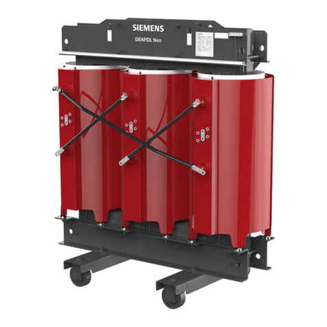
Siemens GEAFOL User manual

GEAFOL- / CARECO-Cast-resin Transformer/ Operating Instructions
© 2021 Siemens Energy Page 1
energy.com
GEAFOL- / CARECO-
Cast-resin Transformer
Operating Instructions
siemens-energy.com
Siemens Energy is a trademark licensed by Siemens AG.
Edition 0
9
/2021

GEAFOL- / CARECO-Cast-resin Transformer/ Operating Instructions
© 2021 Siemens Energy Page 2
Copyright: The copyright to these operating instructions is held by Siemens Energy AG.
These operating instructions must not be wholly or partly reproduced for competitive purposes, used in any unau-
thorized way or made available to third parties without agreement of Siemens Energy AG
siemens-energy.com
6
Connecting
Page 14
6.1 Connection routing
6.2 Connection of high voltage (HV)
6.3 Connection of low voltage (LV)
6.4 Surface preparation
6.5 Fastenings
6.6 Contact pressure
6.7 Grounding of transformers
6.8 Temperature monitoring
6.9 Monitoring devices (Option)
6.10 Siemens Energy Sensformer® (Option)
6.11 Fan (Option)
6.12 Cooler (Option)
6.13 Change in operating voltage
siemens-energy.com
1
General information and safety notes
Page 4
1.1 General information
1.2
Intended use
1.3
Obligations of the user
1.4
The five
safety rules
1.5
Particular types of hazards
1.6
Occupational safety and protective
Equipment
2
Scope
Page 7
3
Usage
Page 7
3.1 Classification in accordance to
IEC 60076-11
4
Description
Page 9
5
Transport, goods receipt, storage
Page 10
5.1
Unloading, lifting by crane
5.2 Transport by road and sea
5.3 Unloading and lifting with forklift truck
5.4 Moving, placement
5.5 Unpacking, examination
5.6 Storage
5.7 Covers on high-voltage tappings and
tubes of delta connection
5.8 Disassembly of delta connections
5.9 Setting up
5.10 Minimum clearances
5.11 Ventilation of the transformer room
7
Commissioning
Page 18
8
Inspection and cleaning
Page 19
9
Faults, causes and remedies
Page 20
10
Recycling and disposal
Page 21
11
Relevant standards
Page 21
12
EC declaration of conformity
Page 22

GEAFOL- / CARECO-Cast-resin Transformer/ Operating Instructions
© 2021 Siemens Energy Page 3
Warning notice system
This manual contains notices you have to observe in order
to ensure your personal safety, as well as to prevent dam-
age to property. The notices referring to your personal
safety are highlighted in the manual by a safety alert sym-
bol, notices referring only to property damage have no
safety alert symbol. These notices shown below are graded
according to the degree of danger.
DANGER
Indicates that death or severe personal injury will
result if proper precautions are not taken.
WARNING
Indicates that death or severe personal injury may
result if proper precautions are not taken
CAUTION
indicates that minor personal injury can result if
proper precautions are not taken.
NOTICE!
indicates that property damage can result if proper
precautions are not taken.
If more than one degree of danger is present, the warning
notice representing the highest degree of danger will be
used. A notice warning of injury to persons with a safety alert
symbol may also include a warning relating to property
damage.
Qualified Personnel
The product/system described in this documentation may be
operated only by personnel qualified for the specific task in
accordance with the relevant documentation, in particular its
warning notices and safety instructions. Qualified personnel
are those who, based on their training and experience, are
capable of identifying risks and avoiding potential hazards
when working with these products/systems.
Proper use of Siemens products
Note the following:
WARNING!
Siemens Energy products may only be used for the
applications described in the catalog and in the relevant
technical documentation. If products and components from
other manufacturers are used, these must be recommended
or approved by Siemens Energy. Proper transport, storage,
installation, assembly, commissioning, operation and
maintenance are required to ensure that the products
operate safely and without any problems. The permissible
ambient conditions must be complied with. The information
in the relevant documentation must be observed.
Disclaimer of Liability
We have reviewed the contents of this publication to ensure
consistency with the product described.
Since variance cannot be precluded entirely, we cannot
guarantee full consistency. However, the information in this
publication is reviewed regularly and any necessary
corrections are included in subsequent editions.

GEAFOL- / CARECO-Cast-resin Transformer/ Operating Instructions
© 2021 Siemens Energy Page 4
General information and
safety notes
1.1 General information
Note
Siemens Energy AG does not accept any liability for
damage and failures that result from the non-ob-
servance of these operating instructions.
These operating instructions are part of the transformer
delivery. Store the operating instructions near the
transformer. Please read the operating instructions prior to
handling the transformer and observe the information they
contain. This is how you ensure safe and disturbance-free
function.
Note
In addition to these operating instructions, special
contractual agreements and technical documentation
apply to a special transformer design and the associ-
ated supplementary equipment.
Please refer to the other operating instructions supplied
with the product.
The described transformers correspond to the state-of-the-art
at the time these operating instructions were printed.
Siemens Energy AG reserves the right to change individual
components and accessory parts in the interest of further
development. The changes serve to improve the
performance and safety. The significant features are
retained. The operating instructions are always being
updated with new contents.
The latest versions of the operating instructions, the
declaration of incorporation and the declarations of
conformity are available in electronic form in the
Online Support
(https://www.siemens-
energy.com/global/en/offerings/power-
transmission/transformers/geafol-
transformers.html#Downloads)
If you have any technical questions, please contact
Technical Support
(kirchheim-sck.energy@siemens-energy.com)
or the local contact addresses on the back of this manual.
1.2 Intended use
The transformers described in these operating instructions
have been designed for stationary use in general engineering
applications.
Unless otherwise agreed, the transformers have been
designed for use in plants and equipment in industrial
environments.
The transformers have been built based on state-of-the-art
technology and are shipped in an operationally reliable
condition. Changes made by users could affect this
operational reliability and are forbidden.
The transformer have been designed solely for the
application described in the IEC 60076-11. Do not operate
the transformer outside the specified power limit. Other
operating conditions must be contractually agreed.
1.3 Obligations of the user
The company operating the unit must ensure that all persons
assigned to work on the transformer have read and
understood these operating instructions and that they
comply with them in all points in order to:
Eliminate the risk to life and limb of users and others
Ensure the operational safety of the transformer.
Avoid disruptions and environmental damage
through incorrect use.
Comply with the following safety instructions:
Shut down the transformer and disconnect the power before
you carry out any work on them.
Make sure that the transformer cannot be turned on
accidentally, e.g. lock the key-operated switch. Place a
warning notice at the drive connection point which clearly
indicates that work is in progress on the transformer.
Carry out all work with great care and with due regard to
"safety".
For all work, carefully comply with the relevant regulations
for work safety and environmental protection.
Comply with the instructions on the rating plates and
warning plates attached to the transformer. The rating plates
and warning plates must be kept free from paint and dirt at
all times. Replace any missing rating or warning plates.
In the event of changes during operation, switch off the
drive unit immediately.

GEAFOL- / CARECO-Cast-resin Transformer/ Operating Instructions
© 2021 Siemens Energy Page 5
Take appropriate protective measures to prevent accidental
contact.
Take appropriate protective measures to prevent accidental
contact with parts and equipment that heat up to over +70
°C.
When removing protective equipment, keep fasteners in a
safe place. Re-attach removed protective equipment before
commissioning.
Do not place any objects on the transformer.
Do not carry out any welding work on the transformer. Do
not use the transformer as a grounding point for welding
work.
Carry out equipotential bonding in accordance with
applicable regulations and directives by electrotechnology
specialists.
Comply with the permissible tightening torque of the
fastening bolts.
Replace damaged bolts with new bolts of the same type and
strength class.
Siemens Energy AG accepts the warranty only for original
spare parts.
The manufacturer who installs the transformer in a plant
must include the regulations contained in the operating
instructions in its own operating instructions.
If you have any questions, please contact the manufacturer's
factory (See back of these operating instructions).
1.4 The five safety rules
For your own personal safety and to prevent material
damage when carrying out any work, always observe the
safety-relevant instructions and the following five safety
rules according to
EN 50110-1 Working in a voltage-free state. Apply the five
safety rules in the sequence stated before starting work.
After the work has been completed, undo the measures
taken in the reverse order.
Five safety rules :
1. Disconnect. Also disconnect the auxiliary
circuits, for example the anti-condensation
heating
2. Secure against reconnection
3. Verify absence of operating voltage
4. Ground and short circuit
5.
Cover or safeguard neighboring live parts

GEAFOL- / CARECO-Cast-resin Transformer/ Operating Instructions
© 2021 Siemens Energy Page 6
1.5 Particular types of hazards
DANGER!
High Voltage!
Do not approach the transformer or re-
move protective covers until the trans-
former is de-energized.
WARNING!
Extreme surface temperatures!
Hot surfaces over +55 °C pose a burn
risk.
Measure the surface temperature be-
fore working on the transformer.
Do not touch the transformer as long
as the surface temperature is not be-
low +55°C.
WARNING!
Sharp edges and corners!
General risk of injury by sharp edges
and corners.
WARNING!
Falling!
General risk of injury by falls.
Use only self-locking climbing assis-
tance
WARNING!
Magnetic field!
The transformer generates a magnetic
field.
People with pacemakers must stay at
least 3 m away from the transformer
1.6 Occupational safety and
protective equipment
Read operating instructions
Wear protecting gloves
Wear protecting glasses
Wear safety shoes
Secure the transformer against being
switched on again during work!

GEAFOL- / CARECO-Cast-resin Transformer/ Operating Instructions
© 2021 Siemens Energy Page 7
Scope
These operating instructions apply to cast-resin
transformers in three-phase or single-phase design
including all special transformers such as converter and
starpoint transformers of the series
GEAFOL / GEAFOL Neo; Typ 4G… and
CARECO / CARECO Neo; Typ 4G…
Rating plate
On the transformer and the housing (if any) is a rating
plate with the nominal values and define operating condi-
tions.
Usage
Unless otherwise agreed, the transformers are designed in
accordance with the applicable standards for the following
cooling air values:
•40° Celsius at any given time
• 30° Celsius monthly average of the hottest month
•20° Celsius yearly average
GEAFOL-/CARECO-transformers intended for installation at
altitudes over 1,000 m above sea level are identified as
such on the rating plate, which cites the maximum permis-
sible installation elevation.
3.1 Classification in accordance
to IEC 60076-11
GEAFOL-/CARECO transformers fulfil the classes defined in
EC 60076-11:
Environmental class
GEAFOL/CARECO: Standard E2 - Frequent condensation or
light pollution or combination of both
GEAFOL NEO /CARECO NEO: Standard E3 -
Frequent condensation or heavy soiling, even both at the
same time. (E3 for wind turbines on request.)
Fire behaviour class F1
The characteristics of the transformer limit the risk of fire.
Climatic class
The following climate classes are available for
GEAFOL/CARECO transformers:
Climatic class
Temperature for
Transport and
storage Operation
C2* to -25°C to -25°C
C3** to -40°C to -25°C
C4 to -50°C to -40°C
*) Standard for CARECO-transformers
**) Standard for GEAFOL-transformers
For lower ambient temperatures, external preheating
equipment must be installed on site.
Corrosion protection
Corrosion protection is available according to the custom-
er's specification in
C2H (e.g. interior, rural areas), C4H (e.g. industrial atmos-
phere. coastal) or C5H (e.g. aggressive atmosphere, off-
shore) executed. CX (extreme) in agreement with cus-
tomer.
Frequency of energization
The frequency of energization on is limited to max. 3 times
a day, max. 50 times a year, unless otherwise agreed.
Load dump conditions for machine transformers
Max. Voltage rise at load dump 140% of Unenn for max. 5
seconds.
Operating conditions
The requirements at the installation site according to IEC
60076-11, chap. 4.2 must be observed, in particular with
regard to grounding of transformers
Protection of the transformer against overvoltages
Load current harmonic content
Symmetry of three-phase supply voltages
Environmental conditions concerning biological envi-
ronmental conditions, chemically active substances,
mechanically active substances, mechanical conditions
Regenerative mode
CAUTION!
The transformer may only be used in regenerative mode
(Step-up) with an appropriate protective device.

GEAFOL- / CARECO-Cast-resin Transformer/ Operating Instructions
© 2021 Siemens Energy Page 8
Description
1 Low-voltage terminals
2 Lifting lugs
3Lashing lugs
4 High-voltage terminals
5 Delta connection
6 Grounding screw
7Lower core frame
8Wheels, can be turned 90°
9Pulling lugs
10 High-voltage tappings
11 (these may also be on the low-
voltage terminal side)
12 Casted high-voltage winding
13 Connection for temperature
monitoring system
14 Upper core frame
15 Low-voltage winding
Core
Only grain-oriented, cold-rolled sheets insulated on both
sides are used for the iron core. The leg and yoke cross-sec-
tions are staggered with different lamination widths. The
outer legs have miter joints. Legs and yokes are connected
by 45° cuts, and the middle leg with a pointed miter joint
at the yoke junction.
Windings
The high-voltage coils are made of aluminum or copper
foils and high-quality insulating films. Each phase winding
is formed from several separate coils connected in series;
these are encapsulated in resin under vacuum. The
winding ends and tappings are routed to threaded bushes
and are encapsulated with the remainder of the winding.
The low-voltage coils are made of aluminum/copper strips
and resin-impregnated insulating film (prepreg).
Insulation
The insulation structure is dimensioned on the basis of the
impulse voltage distribution. It ensures freedom from par-
tial discharge up to twice the rated voltage, as well as ther-
mal and mechanical strength.
Supports
A clamping arrangement designed specifically for the char-
acteristics of the strip/foil windings and the flexible bracing
of the coils ensure both high short-circuit strength and a
very low noise level.

GEAFOL- / CARECO-Cast-resin Transformer/ Operating Instructions
© 2021 Siemens Energy Page 9
Transport, goods receipt,
storage
5.1 Unloading, lifting by crane
GEAFOL/CARECO transformers must be lifted by the lifting
lugs provided on the upper core frames (Fig. 5.1). The
transformer must be lifted and transported with four indi-
vidual chain strands in the correct angle.
The instructions on the labbels at the lifting lugs must be
observed (see Fig. 5.2, 5.3). If the transformer is delivered
with the housing fully assembled, the relevant information
on the housing must be observed
CAUTION!
Do not push or pull on the high-voltage windings or their
connecting tubes.
5.2 Transport by road and sea
The transformer is designed for accelerations of 10 m/s2 or
1.0 g in all directions during transport. For this purpose,
the transformer must be fixed as described below.
To fix the transformer on the loading area, use an anti-slip
mat or fix the transformer at the crossbar on the floor of
the loading area. Tension belts must then be attached to
the lashing eyes of the upper press frame from the inside
(see Fig. 5-4).
The tensioning straps must not be in contact with the win-
dings of the transformer or the rejections. When
tightening the tensioning straps, make sure that the ten-
sion is applied evenly to the opposite tensioning straps.
CAUTION!
Pulling on the tensioning straps from one side can gene-
rate a permanent skewing of the transformer!
Fig. 5-2: Correct lifting of transformer
Fig. 5-3: Not correct lifting
Fig. 5-1: lifting lugs for crane hook with
labbel
Fig. 5-4: Lashing the transformer to the
loading area

GEAFOL- / CARECO-Cast-resin Transformer/ Operating Instructions
© 2021 Siemens Energy Page 10
5.3 Unloading and lifting with
forklift truck
When using a forklift truck, insert the forks into the trans-
port bridges of the transformer.
NOTICE!
If signs prohibiting transport by forklift are at-
tached near the bottom of the transformer, trans-
port of the transformer by forklift is absolutely
prohibited!. Forklift transports are only permitted
if the transporter ensures that
the transformer is moved horizontally (Fig. 5-5)
the transformer is adequately secured against the risk
of tipping and/or falling and
damage to the iron core between the core frames and
any attached accessories like fans or grounding
switches is reliably prevented.
5.4 Moving, placement
If a transformer is moved on its transport wheels, the pul-
ling lugs in the lower core frames are to be used as points
of application (see figure 5.6).
The drawbar between the towing vehicle and the transfor-
mer must be mounted as horizontally as possible (see fi-
gure 5.7).
WARNING!
Do not pull the drawbar eyes jerkily or from above. (Danger
of tipping over)
WARNING!
The centre of gravity of the transformer is in the upper
half. Make sure that you transport the transformer horizon-
tally.
WARNING!
Moving the transformer on the transport wheels is only
permitted on a firm, level surface.
NOTICE: Moving the transformer on the transport rollers is
permitted up to max. 50 m
5.5 Unpacking, examination
GEAFOL-/CARECO-transformers should be unloaded and
unpacked in a sheltered area and inspected immediately
for trans-portation damage. Any visible damage must be
noted in the transport papers and confirmed by the deliv-
erer. The sender must be informed immediately so that a
suitable claims settlement procedure can be initiated, if
necessary with the participation of the transport insurance
company.
5.6 Storage
If the transformer is not commissioned immediately it must
be stored in a sheltered area that is dry and protected from
sunlight.
The transformer must be packed in a protective film when
being transported on-site or being stored temporarily. This
effectively prevents the ingress of dust and foreign matter.
In order to prevent condensation from forming, an ade-
quate quantity of desiccant agent (such as silica gel) must
be enclosed in the packaging.
Fig. 5-5: Horizontal transportation of trans-
former by forklift
Fig. 5-7: Pulling of transformer with transport wheels
Fig.
5
-
6: Pulling lugs in lower core f
rame

GEAFOL- / CARECO-Cast-resin Transformer/ Operating Instructions
© 2021 Siemens Energy Page 11
Figure 5-10: Detect the end position
of the cover by feeling of the screw
5.7 Covers on high-voltage
tappings and tubes of delta
connection
Transformers for specific applications may have covers on
the high voltage tappings and the tubes of the delta con-
nection (See Figure 5.8) These covers are essential parts of
the insulation system.
The transformer may only be operated if these covers are
correctly installed.
Damaged covers must be replaced BEFORE switching on
the transformer.
WARNING!
Switching on the transformer with missing or
damaged electrical insulation covers may destroy
the transformer.
5.8 Disassembly of delta
connections
WARNING!
Disassembly and fitting of the delta connections is the re-
sponsibility of the customer !
When installing the transformer in confined spaces, it may
be necessary to dismantle the delta connections.
If there are covers at the ends of the switch tubes, open
the cable ties with a spanner and carefully pull the cover
off the screw connection.
Mark the screws and switch tubes with the relevant instal-
lation position BEFORE dismantling the switch tubes!
WARNING!
Tightening the screws of the delta connections with too
low torque or mixing up the screws of can lead to serious
damage to the transformer!
CAUTION!
The screws for fixing the switch tubes may have different
lengths. Mixing up the screws can result in the torque be-
ing achieved without the switch tubes being pressed
against the contact surfaces.
Figure 5-9: Position of the washers at
the delta connection Anschluss
Figure 5-8: Covers on high-voltage tap-
pings and tubes of delta connection

GEAFOL- / CARECO-Cast-resin Transformer/ Operating Instructions
© 2021 Siemens Energy Page 12
Bild 5-11: Position der Farbmarkierung
auf Schelle nach dem Anziehen
The arrangement of the switch tubes and washers is
shown in Fig. 5-9. All six screws of the switch tubes must
then be tightened with a torque wrench (torque for M10
with 45 Nm, for M12 with 75 Nm).
If there are covers on the switch tubes, push the cover
onto the connection cone until the screw of the contact
connection can be felt through the cover (see Fig. 5.10).
Position the clamp and tighten the hexagon of the clamp
until the front edge of the white marking on the band is
flush with the body of the clamp (See Figure 5.11)
5.9 Setting up
DANGER!
Cast-resin transformers are not safe to touch. The power
must be shut off before work is performed on the
transformers. Applicable regulations must be observed.
GEAFOL-/CARECO-transformers should be installed only in
a sheltered area or cell that is dry and protected from
sunlight, where the degree of protection assured is at least
IP 20. If appropriately coated with special paint and if an
outdoor housing is used, they are also suitable for
installation outdoors (minimum IP 23). GEAFOL cast-resin
transformers need an adequate supply of fresh air to
dissipate the heat loss. Approximately 200 m3 of fresh air
per hour and for each kW of heat loss is the recommended
value; more information can be found in the GEAFOL
Planning Guidelines.
5.10 Minimum clearances
Make sure that the clearances from the surface of the cast-
resin coils to the walls, busbars, grounded parts, and other
elements satisfy the applicable installation and safety regu-
lations
(see Table 5-1 and Fig. 5-10).
For installation above 1000 m above sea level, the mini-
mum distances according to Table 5-1 shall be increased by
one percent for every 100 metres of altitude by which the
installation altitude exceeds 1000 m.
Maxi-
mum
voltage
for
equip-
ment
Um1)
Rated lightning
impulse with-
stand
voltage ULI1)
(See type plate)
Minimum clearances
(see Fig 5.10)
[kV] [kV] a**
[mm]
b**
[mm]
c**
[mm]
d***
12 75 120 *55
24 95 160 *85
24 125 220 *105
36 145 270 *125
36 170 320 *170
52 250 480 *300
72,5 325 630 *450
1) see IEC 60071
* If there are high-voltage tappings on this side,
the value in column a applies to the clearance b;
otherwise, the value in column c applies.
** Distance from blank, energized parts to walls or
OS cables. For transformers with complete insu-
lation at connection bars and switch tubes (bot-
tom and top), the values of dimension c are to
be used for the minimum distances of dimension
a.
*** The distance d between the delta connections is
defined constructively by the manufacturer
Table 5
-
1

GEAFOL- / CARECO-Cast-resin Transformer/ Operating Instructions
© 2021 Siemens Energy Page 13
5.11 Ventilation of the
transformer room
Every transformer has heat loss occurs during the opera-
tion. This heat must be dissipated from the transformer
room.
A good cooling effect is achieved if the cooling air flows in
at the bottom of the room and flows out at the top of the
room
(see Fig. 5-11).
The cooling type is shown on the nameplate. The code of
the cooling type is shown in Table 5-2.
Note:
A transformer designed up to a defined rated power with
natural ventilation cooling, and for a higher rated power
with forced cooling, is marked with ON/AF.
CAUTION!
Operate the transformer at least with the type of cooling
specified on the nameplate.
Make sure that the ventilation ducts are not covered. If the
supply air is heavily polluted, it must be filtered.
Make sure that there is no condensation above the trans-
former that steadily drips into the transformer.
If the transformer is regularly switched off for several days,
make sure that no condensation occurs during this time.
This prompts the transformer to become dirty.
If the cooling effect is too low, a ventilation system can be
retrofitted.
Housing for outdoor installation
In the event of a storm or heavy rain, water may enter the
interior of the transformer through the ventilation slots. In
this case, make sure that there is a water drain to avoid
larger accumulations of water inside the housing.
DANGER!
Water accumulation inside the transformer housing can
lead to flashovers outside the transformer housing!
WARNING!
The surface temperature on the housing can exceed
55°C degrees.
For more information please see the brochures at following
link:
https://www.siemens-energy.com/geafol
Fig. 5-12: Minimum clearances around GEAFOL cast-resin
transformers with bare tappings and delta connection
tubes
Fig. 5-13: Ventilation of transformer room
Symbol
Cooling medium Air A
Water W
Type of circulation Natural N
Forced F
Table 5-2: Symbols of cooling method

GEAFOL- / CARECO-Cast-resin Transformer/ Operating Instructions
© 2021 Siemens Energy Page 14
Connecting
CAUTION!
Do not climb on connecting tubes of the transformer at
connecting!
CAUTION!
Metallic objects in the coils can destroy the transformer!
The coils must be covered during connection.
6.1 Connection routing
Cast resin transformers allow many connection combina-
tions, both from above and below.
When connecting cables are use, make sure that they fea-
ture adequate strain relief and are routed so that the volt-
age clearances are maintained in line with relevant regula-
tions.
The minimum clearances for cable connections shown in
Table 5.1 and Fig. 5.10 must be observed.
6.2 Connection of high voltage
(HV)
On the high-voltage side, the transformer is connected to
the surfaces of the delta connecting tubes or the terminals
provided on the casted delta connection bar, or to the cast-
on post insulators on the high-voltage pottings (Y connec-
tion).
6.3 A Connection of low voltage
(LV)
On the low-voltage side, the transformer is connected to
the aluminum terminals provided for this purpose. Here
again it must be ensured when connecting cables, that
they feature adequate strain relief to avoid undue mechan-
ical stress at the terminals. The following guidelines must
be observed when connecting the transformer terminals
via expansion straps.
If the low-voltage connection is established with busbars,
an expansion strap (flexible connection element) must be
installed between the transformer and the busbars. This
keeps mechanical stresses away from the transformer (see
Fig. 6-2) and largely prevents transmission of structure-
borne transformer noise. Detailed information on bolted
busbar connections can be found in DIN 43673.
6.4 Surface preparation
Before making any bolted or terminal connections, it is
necessary to remove the thin, invisible layer of oxide,
which is a poor conductor of electricity, from the alumi-
num surface. Therefore, the contact surfaces to the cus-
tomer connections must be made metallically bright. Every
time a point of contact is opened, the aluminum contact
surface must be subjected to the full preparation process
again before it is bolted back together.
Fig. 6-1: Example of connection
Fig. 6-2: Low-voltage end connection with expan-
sion strapp

GEAFOL- / CARECO-Cast-resin Transformer/ Operating Instructions
© 2021 Siemens Energy Page 15
If the transformer is installed indoors in a room where con-
densation is expected, or where corrosive gases are pre-
sent, and if the transformer will be connected to copper
busbars, an aluminum sheet that is copper plated on one
side (the product known by the trade name “Cupal”, for ex-
ample), must be inserted between Cu-Al contact points.
The aluminum side is in contact with the aluminum
terminal. All edges of this sheet must protrude several
millimeters to ensure that any corrosion occurring in the
transition area remains outside the contact zone. Corrosion
can be avoided for the most part by applying a protective
coating to the cut edges of this Cupal sheet.
Tin-plated terminals can be combined with bare aluminum,
copper or silver-plated surfaces.
6.5 Fastenings
Corrosion-proof parts must be used for bolted connections.
Bolts in strength class 8.8 or 10.9 should be used. In order
to transmit the bolting force to the largest possible contact
surface, stiffened washers should be inserted under the
bolt head and the nut. Spring elements are also necessary
to resiliently accommodate heat-generated tension, to
compensate for plastic deformation and maintain the re-
quired minimum contact pressure at all times.
Both conditions can be met by conical spring washers per
DIN 6796, which are used in particular for conductor bar
threaded fastenings.
6.6 Contact pressure
The bolts should be tightened with a torque wrench. This
ensures that the bolt connections are made with adequate
contact pressure.
To compensate for any settling in the joints, it’s advisable
to retighten the bolts after a few hours. However, the
torque then applied should not be greater than the torque
applied in the initial installation.
For tightening the non-greased (dry) screw connections,
we recommend using the tightening torques given in table
6-
Bolt Torque [Nm] dry
M 6 10
M 8 20
M 10 45
M 12 75
M 16 140
Fig. 6-3: Transformer connection with cable lug
Fig. 6-4: Low voltage connection with expansion strap
Table 6-2: Tightening torque values for the phase connections
and tappings

GEAFOL- / CARECO-Cast-resin Transformer/ Operating Instructions
© 2021 Siemens Energy Page 16
6.7 Grounding of transformers
Make sure that the necessary grounding connection is in-
stalled on accessories that are conected to the transformer
after installation. Transformer housings must also be
grounded in accordance with the known grounding specifi-
cations.
The grounding screws are located on the front sides of the
lower press frame (see Fig. 6.5). A PE wiring must be con-
nected here at one position. The dimensioning of the PE
wiring is defined by specific regulations at the installation
site.
For transformers with housing, corresponding grounding
connections are located on the outside of the housing.
6.8 Temperature monitoring
The measuring sensors in the temperature monitoring sys-
tem record the winding temperature. This acts as overload
protection against excessive heat generation in the trans-
former windings.
The temperature monitoring system consists of PTC ther-
mistors, according to DIN 44082 or resistance thermome-
ters (PT100) in accordance with IEC 60751, and the associ-
ated monitoring devices.
The terminal box, the connection diagram of the tempera-
ture monitoring and the specification of the limit tempera-
tures are located on the upper press frame as standard
(Fig. 6-6).
The temperature values for the warning, alarm triggering
or fan control functions must be set on the triggering de-
vice or monitoring system.
6.9 Monitoring devices (Option)
For the activation of error messages on the basis of the
sensor signals, different triggering devices are offered for
GEAFOL/CARERCO transformers, depending on the type
and number of sensors.
For transformers with housings as part of the scope of sup-
ply, the tripping devices are located in the control cabinet
of the housing.
Information for connection and operation of the monitor-
ing devices can be found in the respective operating in-
structions.
Test the function of the triggering devices during commis-
sioning.
Fig. 6-6: Terminal box, connection diagram and limit tem-
peratures on upper press frame (EXAMPLE)
Fig. 6-7: Display of monitoring device (EXAMPLE)
Fig. 6-5: Grounding connection

GEAFOL- / CARECO-Cast-resin Transformer/ Operating Instructions
© 2021 Siemens Energy Page 17
6.10 Siemens Sensformer®
(Option)
The Sensformer is used for digital transmission of the
measurement data in real time. By means of an app, an
overview of the status of the individual transformers be-
comes possible. Likewise, a push message can be sent in
the event of an error message.
The connection of the sensor transformer is located in the
box on the front side of the upper press frame or in the
control cabinet of the housing.
Information on connection and operation are in the app at
the Google Play Store available.
6.11 Fan (Option)
A control unit is required for temperature-dependent
switching on of the fans (AN/AF operating mode). Switch-
ing on and off is carried out via an adjustable time or tem-
perature in the monitoring unit.
Depending on the type, the fan is already connected to a
monitoring device or is intended for the connection to a
control device provided by the customer.
The connections of the fan are located on the fan motor of
the individual fan on the bottom side of the transformer.
• Connect the fan according to the operating instruc-
tions of the fan.
• During commissioning, check the function of all fans
• Ensure that the fans are rotating in the correct direc-
tion
Notice:
On delivery, the default setting of the monitoring system
types T154 and NT935 includes a functional test for fans. If
run in the factory default setting, every 96 hours the fans
will undergo a short test lasting 5 –10 minutes.
6.12 Cooler (Option)
If a cooler is installed in the transformer housing (operat-
ing mode WF), connect the cooler to an external cooling
circuit before switching on the transformer. Take care of
the information on the coolant connection regarding
•type of cooling agent
• max. pressure
•Flow rate
•Max. Input temperature of the coolant
Open the shut-off valves of the cooler before switching on
the transformer.
Follow the operating instructions of the cooler.
Make sure that no power lines are resting on the surface of
the cooler.
Figure 6-10: Power connection of fan
Fig. 6-8: Sensformer
box
Fig. 6-9 Sensformer-App

GEAFOL- / CARECO-Cast-resin Transformer/ Operating Instructions
© 2021 Siemens Energy Page 18
6.13 Modification of high voltage
tappings
By changing the position of the connecting brackets at the
high-voltage coils, the voltage of the transformer can be
changed according to the rating plate (Fig 6.11)
The numbering of the taps is explained on a label on the
upper core frame of the transformer (Fig. 6.12)
WARNING!
The connecting brackets may only be reconnected when
the device is deenergized.
CAUTION!
Operating the transformer with a voltage that does not
correspond to the position of the switching jumpers on the
top voltage taps may cause damage to the transformer.
NOTICE!
The change in voltage can destroy connected components.
All connecting brackets at the HV windings must be fixed
at the same voltage tapping.
NOTICE!
Different positions of the connecting brackets on the indi-
vidual coils can destroy the transformer.
After reattaching, the screws of the connecting brackets
must be tightened to the torque shown on the label (Fig.
6.12)
Cover on taps of connection bar
If there are covers on taps, these must be re-assembled af-
ter the intervention (Fig. 6.13)
Clean the sealing surfaces before reassembling.
Turn the nuts onto the threaded pins by hand until the nut
rests on the cover. Use a wrench and turn the nut 1 1/4
turn.
Fig. 6-11: Operating voltage on the rat-
ing plate depending on the position of
the connecting brackets (SAMPLE)
Fig. 6-12: Information label on the trans-
former regarding numbering and tightening
torque of the taps (SAMPLE)
Fig. 6-13: Cover type A on taps
of Connection bar

GEAFOL- / CARECO-Cast-resin Transformer/ Operating Instructions
© 2021 Siemens Energy Page 19
Commissioning
The transformer must have been cleaned and it should not
contain any foreign objects (see also Install, page 7).
•Compare the technical data on the rating plate
attached to the transformer to the customer’s
requirements.
• Tighten all contact connections to the torque stated in
Table 6.2.
NOTICE!
If the ambient conditions are outside the transformer spec-
ification (e.g. ambient temperature too low), the appropri-
ate conditions must be established before switching on.
When large transformers are switched on, in isolated cases
visible sparks may occur on the outside (especially in the
area of the core and the clamped parts), but these will
soon subside.
This effect occurs for reasons of physics and has no influ-
ence on operating safety; it is not a defect. Due to the low
attenuation, it may take the switch-on currents of GEAFOL
cast-resin transformers some time to decay. Refer to the
test report for the exact values. This must be considered
when selecting fuses and/ or relay times.
If protection settings are incorrect, the transformer will be
switched off during the transient response of the current.
This will lead to high excess voltages in the transformer
windings, where they may cause damage.
Inspection and cleaning
GEAFOL/CARECO transformers are practically maintenance-
free. If they are operated in very dusty installations, for in-
stance in rolling mills, we recommend cleaning several
times a year. Typically, once every year, the contact bolts,
warning functions, and the operation of any attached fans
should be checked.
The transformer must be switched off on all sides before
starting maintenance work. All terminals must be short-cir-
cuited and grounded. The safety regulations must be ob-
served.
DANGER!
Check that the transformer is de-energized before
approaching the transformer or you do not remove
protective covers. Secure the transformer against
unauthorised switching on.
NOTICE!
Dust and dirt are the main causes of transformer overheat-
ing and electrical short circuits. Dust deposits lead to
higher operating temperatures.
NOTICE!
Make sure that used tools and cleaning equipment are
completely removed from the transformer again after the
inspection.
NOTICE!
Do not use cleaning equipment with metal brushes. Loose
metal wires can cause severe damage to the transformer.
Do not use sharp-edged tools!
DANGER!
Do not switch on transformer until it is completely dry!

GEAFOL- / CARECO-Cast-resin Transformer/ Operating Instructions
© 2021 Siemens Energy Page 20
Overview inspection activities
Remedy Time interval (rec-
ommendation)
Description of the activity
Visual check 1x per year Check for soiling, damage, soot deposits, infestation by animals
Checking that the current-carrying connections are free of corrosion
Cleaning the transfor-
mer
1x per year/
In case of in-
creased pollution
several times a
year
Vacuuming of loose particles and dirt in the cooling channels of the
upper and lower voltage coils with a hoover. Compressed air can also be
used.
Cleaning or hoover the auxiliary equipment such as fans, surge arresters,
connection terminals and the mounting substructure.
Rub down the dirty surfaces of the transformer with a cloth soaked in a
commercially available surfactant-based cleaner. Then wipe with a dry.
Cleaning the floor around the transformer
Housing check 1x per year Check the function of the door locks
Check the presence of the warning stickers "High voltage" and if
necessary warning stickers "Hot surface" (see chapter 1).
Check the cleanliness of the air inlet and outlet openings.
Check that the protective housing is clean and dry.
Clean if necessary.
Screw connections of
all electrical connec-
tions and earthing
1x per year Check the torque of the screw connections of all electrical terminals, the
high-voltage tappings, and the connections from one system to another
in the case of double-tier transformer. Values of the torques see chap. 6,
table 6.2
Control of the warn-
ing functions
1x per year and af-
ter error messages
Visually check the clamp connections/ Retighten the screw terminals on
the transformer and in the control cabinet on the housing (if present)
Carry out the function check according to the specifications in the
operating instructions of the sensor/evaluation unit.
Fan check (if
available)
1x per year Check attached fans for their function, cleanliness and operating
properties in accordance with the specific operating instructions
Cooler check (if
present)
1x per year Check coolers for their function, cleanliness and operating properties in
accordance with the specific operating instructions.
Note: The time interval for changing the cooling medium is defined in
the operating instructions for the cooler
Table 8-1
This manual suits for next models
1
Table of contents
Other Siemens Transformer manuals

Siemens
Siemens SIDOOR 6FB1112-0AT20-2TR0 User manual

Siemens
Siemens SIDOOR AT40 User manual

Siemens
Siemens GEAFOL Neo User manual

Siemens
Siemens 3WN6 User manual

Siemens
Siemens MICROMASTER 440 GX Technical specifications

Siemens
Siemens MICROMASTER 430 Operating and maintenance instructions

Siemens
Siemens 4NC51-21 Series User manual

Siemens
Siemens LI EC Series User manual

Siemens
Siemens 3VL9 8TC00 Series User manual

Siemens
Siemens SEM3 User manual