manuals.online logo
Brands
  1. Home
  2. •
  3. Brands
  4. •
  5. Siemens
  6. •
  7. Transformer
  8. •
  9. Siemens SEM3 User manual

Siemens SEM3 User manual

SEM3 Split Core Current Transformer Install Guide
E492531
7KT1280-5MA...
i. In accordance with NEC, CTs may not be installed in
any panel board where they exceed 75% of the wiring
space of any cross sectional area.
ii. Do not install a Current Transformer in an area where
it would block ventilation openings.
iii. Do not install a Current Transformer in area of breaker
arc venting.
iv. Not suitable for Class 2 wiring methods and not
intended for connection to Class 2 equipment.
Field-installed Class 2, Class 3, and other low voltage
conductors shall be separated by a minimum 1/4 inch
(6.4mm) from factory- or field-installed electric light,
power, Class 1, non-power-limited fire alarm circuit
conductors, and medium power network-powered
broadband communications cables. Separation of
conductors may be obtained by clamping, routing,
or an equivalent means.
v. Secure Current Transformers and route conductors so
that they can not directly contact live terminals or
current carrying conductors.
The SEM3 series Split Core Current Transformers measure
rated currents up to 2000 Amps. They may be field installed
within distribution and control equipment such as panel
boards, switchboards, industrial control equipment, and
energy-monitoring / management equipment to measure
current on the service entrance or branch circuit conductors.
Specifications
Ratings:
Primary voltage: 600 VAC
Overvoltage category: CAT IV (service entrance) for
pollution degree 3
Line frequency: 50/60Hz
Secondary (output) current: 100mA
Listed to: UL 2808
Environmental:
Operating temperature: -40°F to 158°F (-40°C to 70°C)
Operating humidity: 0 to 95% non-condensing
Pollution degree: 3 for CAT IV, 600 VAC
Indoor use: Suitable for indoor use
Electrical:
Accuracy class: 0.5S
Protection: Shorting of CT is not needed since CT already
includes shorting means, voltage limited to 5V+/-2V.
Lead wires: 18AWG, Stranded 16/30, 600V, UL style
1015, Brown/Yellow twisted pair, 2 turns per inch.
Type
Rated primary
current Ip (A)
Rated secondary
current Is (mA)
7KT1280-5MA00 50 100
7KT1280-5MA01 125 100
7KT1280-5MA02 250 100
7KT1280-5MA03 400 100
7KT1280-5MA04 600 100
7KT1280-5MA05 800 100
7KT1280-5MA06 1200 100
7KT1280-5MA07 1600 100
7KT1280-5MA08 2000 100
Kt=10 (5ON/5OFF)
LOAD
+
–
Kt=10 (5ON/5OFF)
Install CT around conductor.
Connect CT meter module.
Install meter module in rack.
Installing the Current Transformer
Use the current transformer only in the manner described
in this manual. If the current transformer is used in a manner
not specified by the manufacturer, the internal protection of
current transformer may be impaired.
Factory Installation
1. Connect the CT secondary wires to the SEM3 Meter
Module (figure 1) as per metering device instructions.
2. Insert the meter module into the rack and select the
proper phase (figure 2).
3. Identify the conductor on which you wish to install
the CT and its associated breaker or switch.
4. Disconnect conductor from breaker or switch.
5. Slip the CT over the conductor wire such that the CT
arrow is oriented toward LOAD (figure 3). Make sure CT
is properly secured to conductor or panel to prevent
potential movement.
6. Re-connect the conductor wire.
7. Repeat steps 1-6 for other conductors as required.
8. Turn on breaker or switch when complete.
Field Installation
1. Identify the conductor on which you wish to install the
CT and its associated breaker or switch.
2. Open current transformer.
3. Slip the CT over the conductor wire such that the CT
arrow is oriented toward LOAD (figure 3). Make sure CT
is properly secured to conductor or panel to prevent
potential movement.
4. Close current transformer.
5. Connect the CT secondary wires to the SEM3 Meter
Module (figure 1) as per metering device instructions.
6. Insert the meter module into the rack and select the
proper phase (figure 2).
7. Repeat steps 1-6 for other conductors as required.
8. Turn on breaker or switch when complete.
NOTE – These instructions do not purport to cover all details or variations in equipment,
or to provide for every possible contingency to be met in connection with installation,
operation or maintenance. Should further information be desired or should particular
problems arise, which are not covered sufficiently for the purchaser’s purposes, the matter
should be referred to the local Siemens sales office. The contents of this instruction manual
shall not become part of or modify any prior or existing agreement, commitment or
relationship. The sales contract contains the entire obligation of Siemens. The warranty
contained in the contract between the parties is the sole warranty of Siemens. Any
statements contained herein do not create new warranties or modify the existing warranty.
Trademarks – Unless otherwise noted, all names identified by ® are registered trademarks
of Siemens AG or Siemens Industry, Inc. The remaining trademarks in this publication may
be trademarks whose use by third parties for their own purposes could violate the rights
of the owner.
Published by
Siemens Industry, Inc. 2019.
Siemens Industry, Inc.
5400 Triangle Parkway
Norcross, GA 30092
Figure 1
Yellow
Brown
Figure 2
Figure 3
For more information, please
contact our Customer Support
Center.
Phone: 1-800-333-7421
E-mail: pds.techsupport.us@
siemens.com
usa.siemens.com/sem3
Ref. No. R814372 Rev. 01
© 2019 Siemens Industry, Inc.
Hazardous Voltage.
Will cause death or serious injury.
Turn off and lock out all power supplying this
equipment before working on this device.
Replace all covers before power supplying
this device is turned on.
Tensión peligrosa.
Puede causar la muerte o lesiones graves.
Desenergice totalmente el equipo antes de
instalar o darle servicio.
Reemplace todas las barreras y cubiertas
antes de energizar el interruptor.
Tension dangereuse.
Provoquera la mort ou des blessures graves.
Mettre hors tension et cadenasser verrouiller
l’alimentation avant d’intervenir sure cet appareil.
Remettre tous les couvercles en place avant
de remettre cet appareil sous tension.
Danger Danger
Peligro
DANGER
To reduce the risk of electrical shock, always open or
disconnect circuit from power-distribution system (or service)
of building before installing or servicing current transformers.

This manual suits for next models

9

Other Siemens Transformer manuals

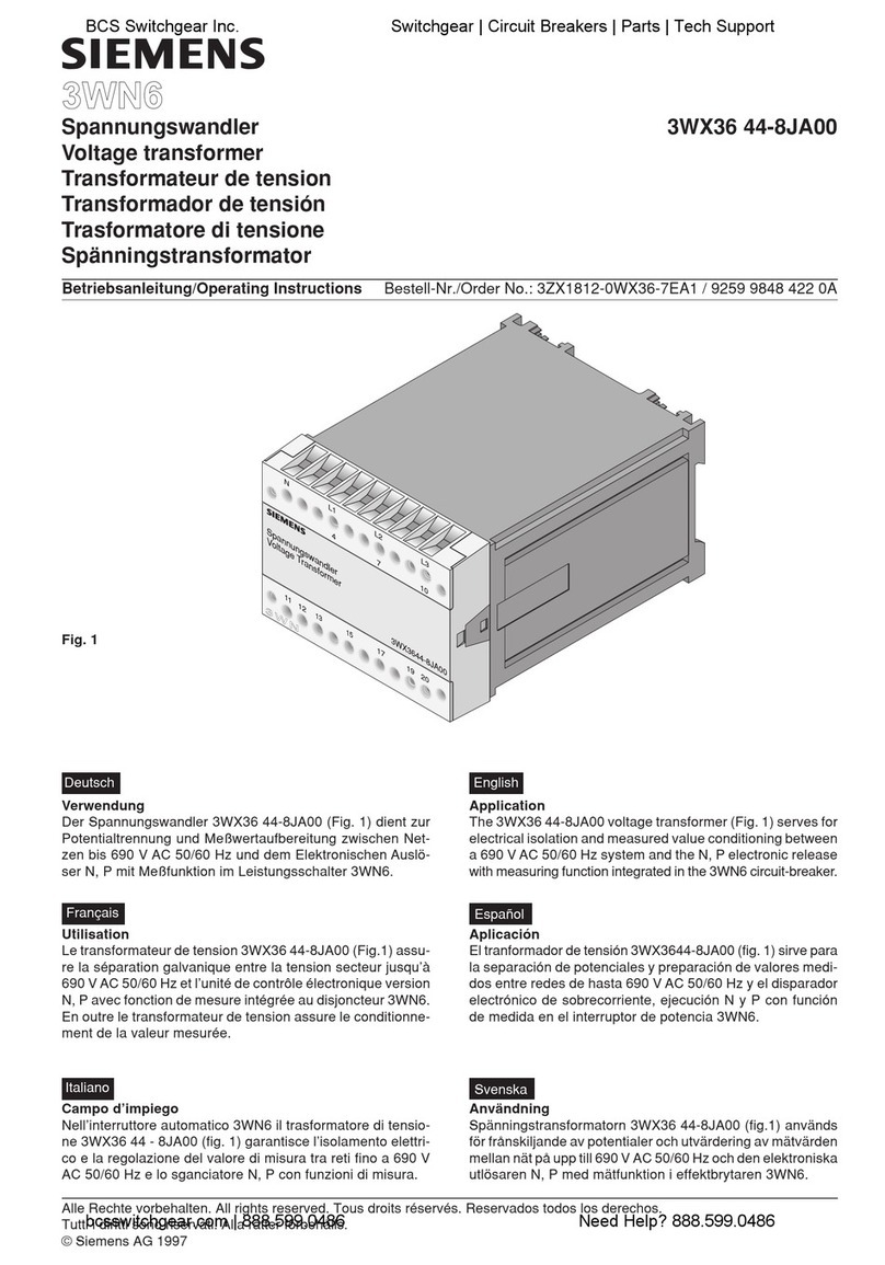
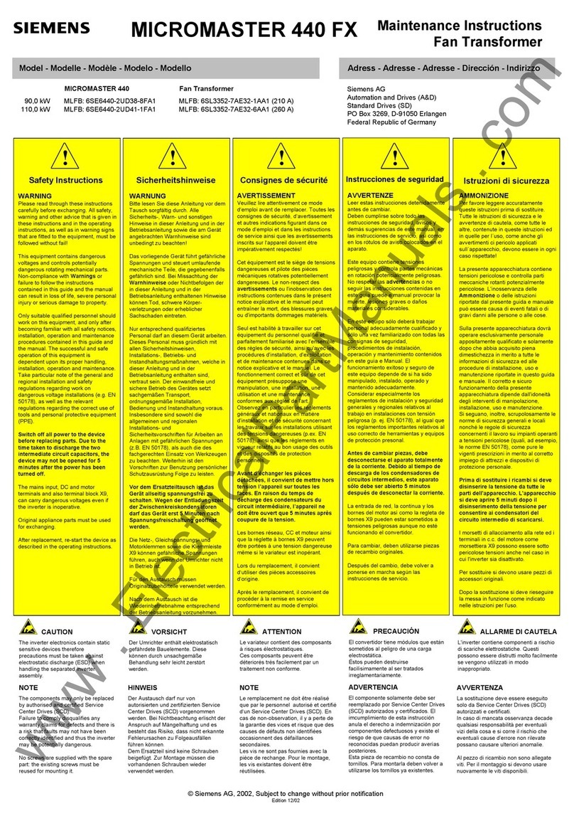
Siemens GEAFOL User manual

Siemens

Siemens GEAFOL User manual

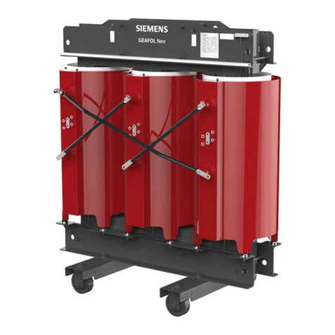
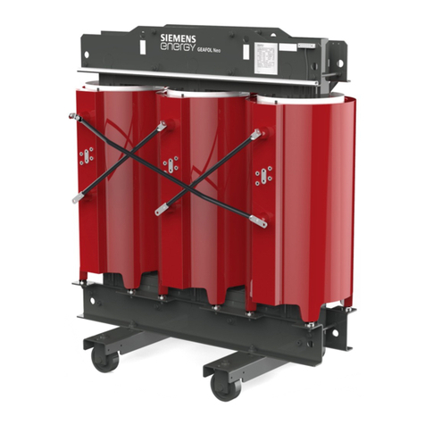
Siemens GEAFOL Neo User manual

Siemens

Siemens GEAFOL Neo User manual

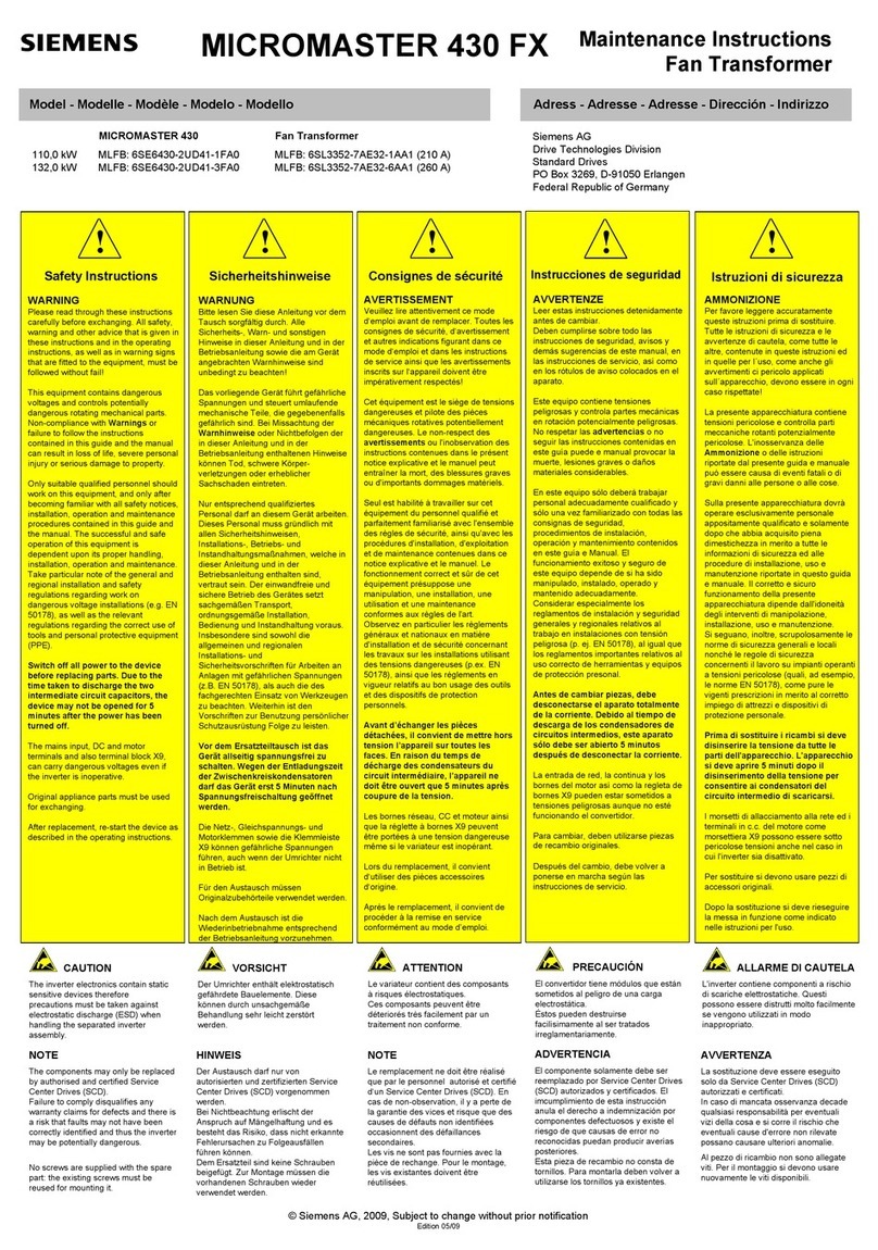
Siemens MICROMASTER 430 Operating and maintenance instructions

Siemens

Siemens MICROMASTER 430 Operating and maintenance instructions

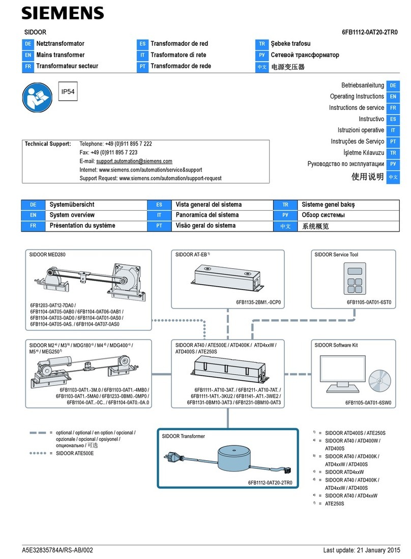
Siemens SIDOOR AT40 User manual

Siemens

Siemens SIDOOR AT40 User manual

Siemens 4NC51-21 Series User manual

Siemens

Siemens 4NC51-21 Series User manual

Siemens MICROMASTER 440 GX Technical specifications

Siemens

Siemens MICROMASTER 440 GX Technical specifications

Siemens 3WX3642-2 0 Series User manual

Siemens

Siemens 3WX3642-2 0 Series User manual

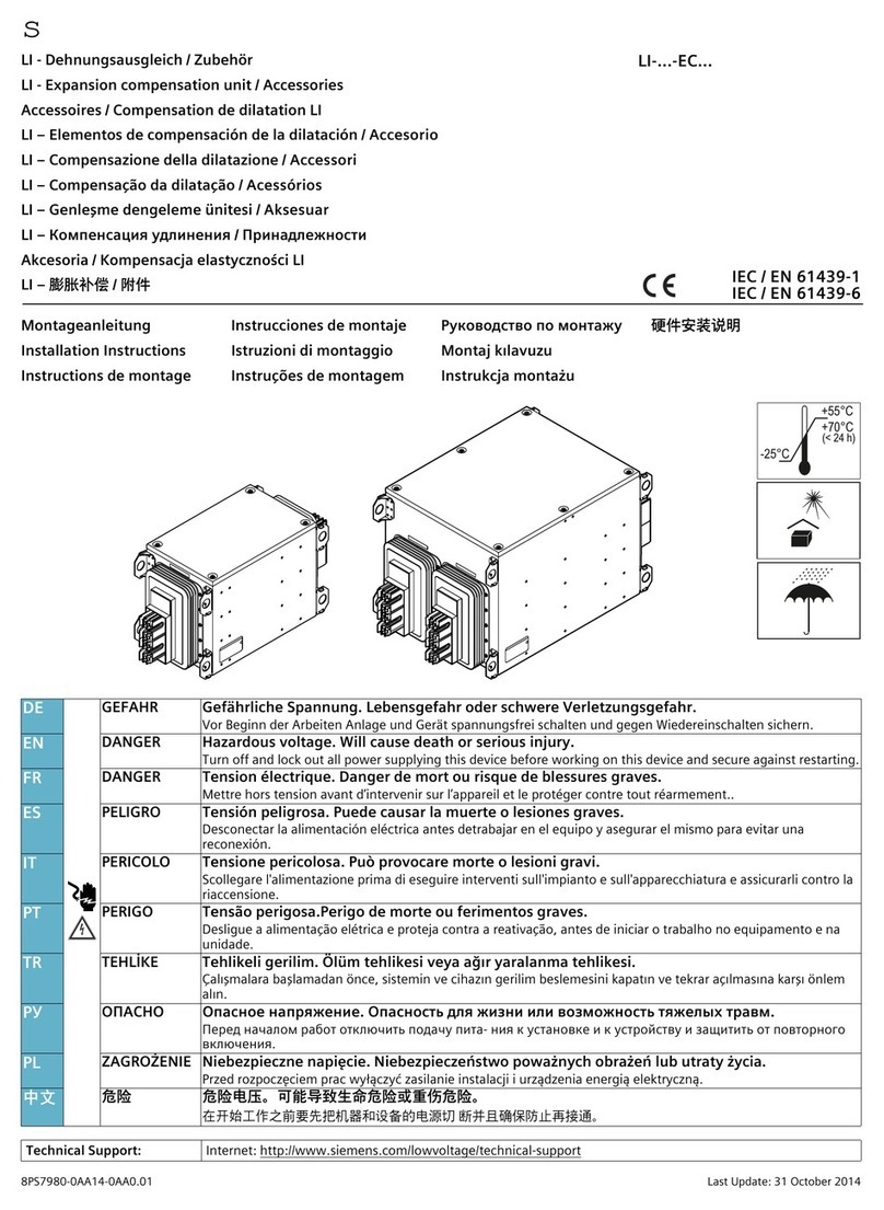
Siemens LI EC Series User manual

Siemens

Siemens LI EC Series User manual

Siemens NGSD060 User manual

Siemens

Siemens NGSD060 User manual

Siemens 3VL9 8TC00 Series User manual

Siemens

Siemens 3VL9 8TC00 Series User manual

Siemens MICROMASTER 440 Operating and maintenance instructions

Siemens

Siemens MICROMASTER 440 Operating and maintenance instructions

Siemens SIDOOR 6FB1112-0AT20-2TR0 User manual

Siemens

Siemens SIDOOR 6FB1112-0AT20-2TR0 User manual

Siemens MICROMASTER 430 Operating and maintenance instructions

Siemens

Siemens MICROMASTER 430 Operating and maintenance instructions

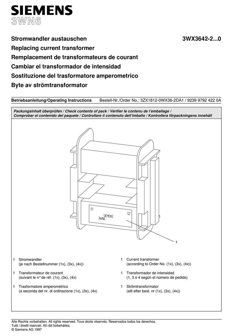
Siemens 3WN6 User manual

Siemens

Siemens 3WN6 User manual

Siemens 3VA9077-0NA10 User manual

Siemens

Siemens 3VA9077-0NA10 User manual

Siemens 7XR6004 Series Manual

Siemens

Siemens 7XR6004 Series Manual

Popular Transformer manuals by other brands

Superior Electric POWERSTAT POWERKOTE 21 Series Instructions for installation, operation and maintenance

Superior Electric

Superior Electric POWERSTAT POWERKOTE 21 Series Instructions for installation, operation and maintenance

Cloud CXL-46T installation instructions

Cloud

Cloud CXL-46T installation instructions

DiodeDrive LVT-W-12VAC Series user manual

DiodeDrive

DiodeDrive LVT-W-12VAC Series user manual

marklin 60052 user guide

marklin

marklin 60052 user guide

Altec Lansing 15550A TRANSFORMERS manual

Altec Lansing

Altec Lansing 15550A TRANSFORMERS manual

Dewenwils TD-120-12WF-1 WiFi manual

Dewenwils

Dewenwils TD-120-12WF-1 WiFi manual

Whale INSTANT MATCH SDS236T Quick connect guide

Whale

Whale INSTANT MATCH SDS236T Quick connect guide

3B SCIENTIFIC PHYSICS U33300 instruction sheet

3B SCIENTIFIC PHYSICS

3B SCIENTIFIC PHYSICS U33300 instruction sheet

Altec Lansing 15335A Specifications

Altec Lansing

Altec Lansing 15335A Specifications

CyberPower OL6KRT2UTF user manual

CyberPower

CyberPower OL6KRT2UTF user manual

MOULDPRO MHN-PS01 user guide

MOULDPRO

MOULDPRO MHN-PS01 user guide

ABB FLM 1000 Installation instruction

ABB

ABB FLM 1000 Installation instruction

Monacor Security TVI-100 manual

Monacor

Monacor Security TVI-100 manual

Altec Lansing 15567A TRANSFORMER manual

Altec Lansing

Altec Lansing 15567A TRANSFORMER manual

Graco InvisiPac Instructions and parts

Graco

Graco InvisiPac Instructions and parts

Professional Pool Products RC04 installation manual

Professional Pool Products

Professional Pool Products RC04 installation manual

Campbell CS15-L instruction manual

Campbell

Campbell CS15-L instruction manual

Camille Bauer SIRAX CT3 Series operating manual

Camille Bauer

Camille Bauer SIRAX CT3 Series operating manual

manuals.online logo
manuals.online logoBrands
  • About & Mission
  • Contact us
  • Privacy Policy
  • Terms and Conditions

Copyright 2025 Manuals.Online. All Rights Reserved.