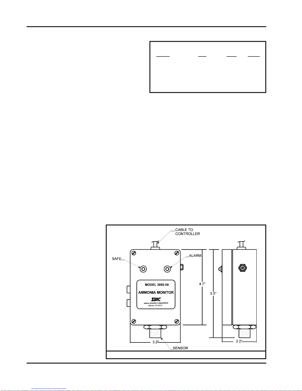
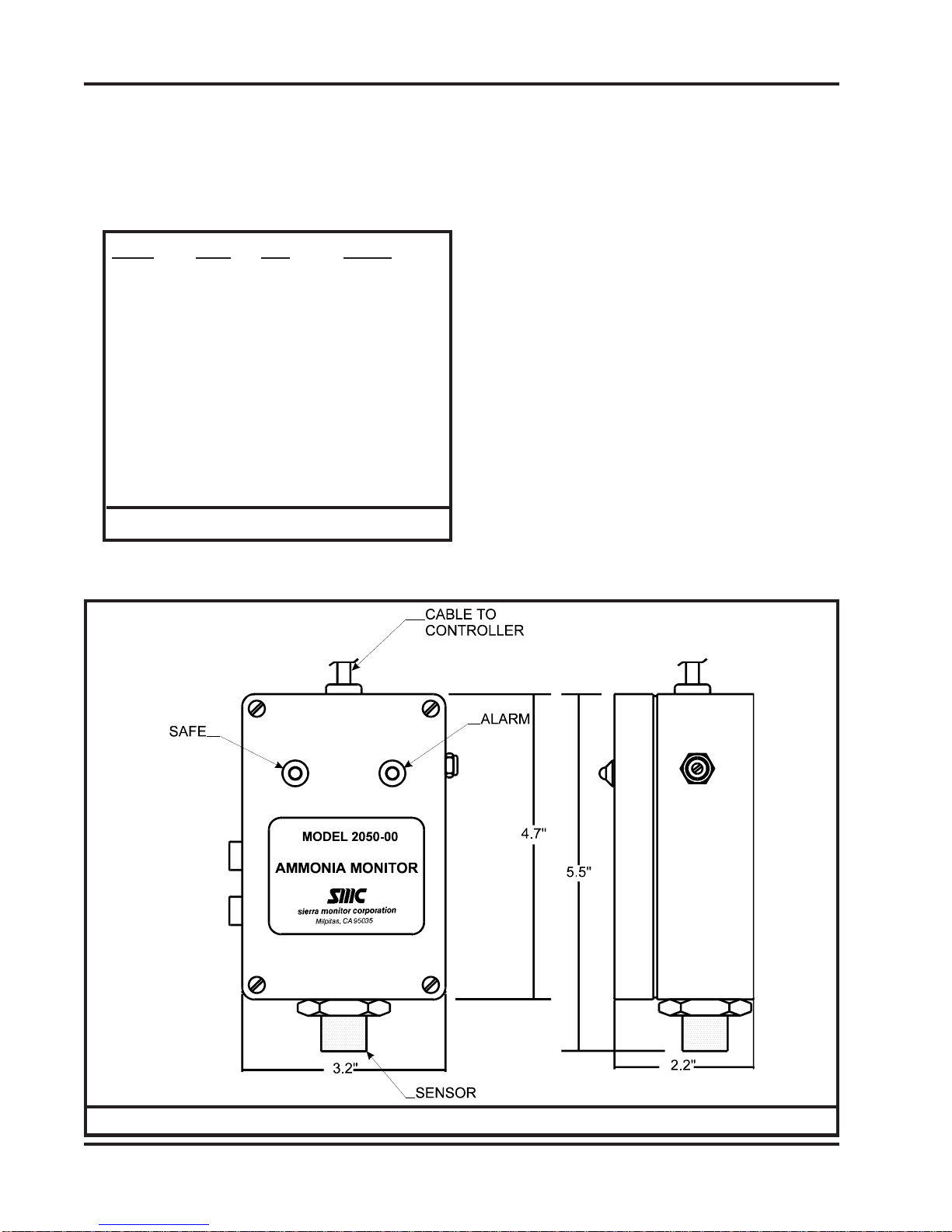
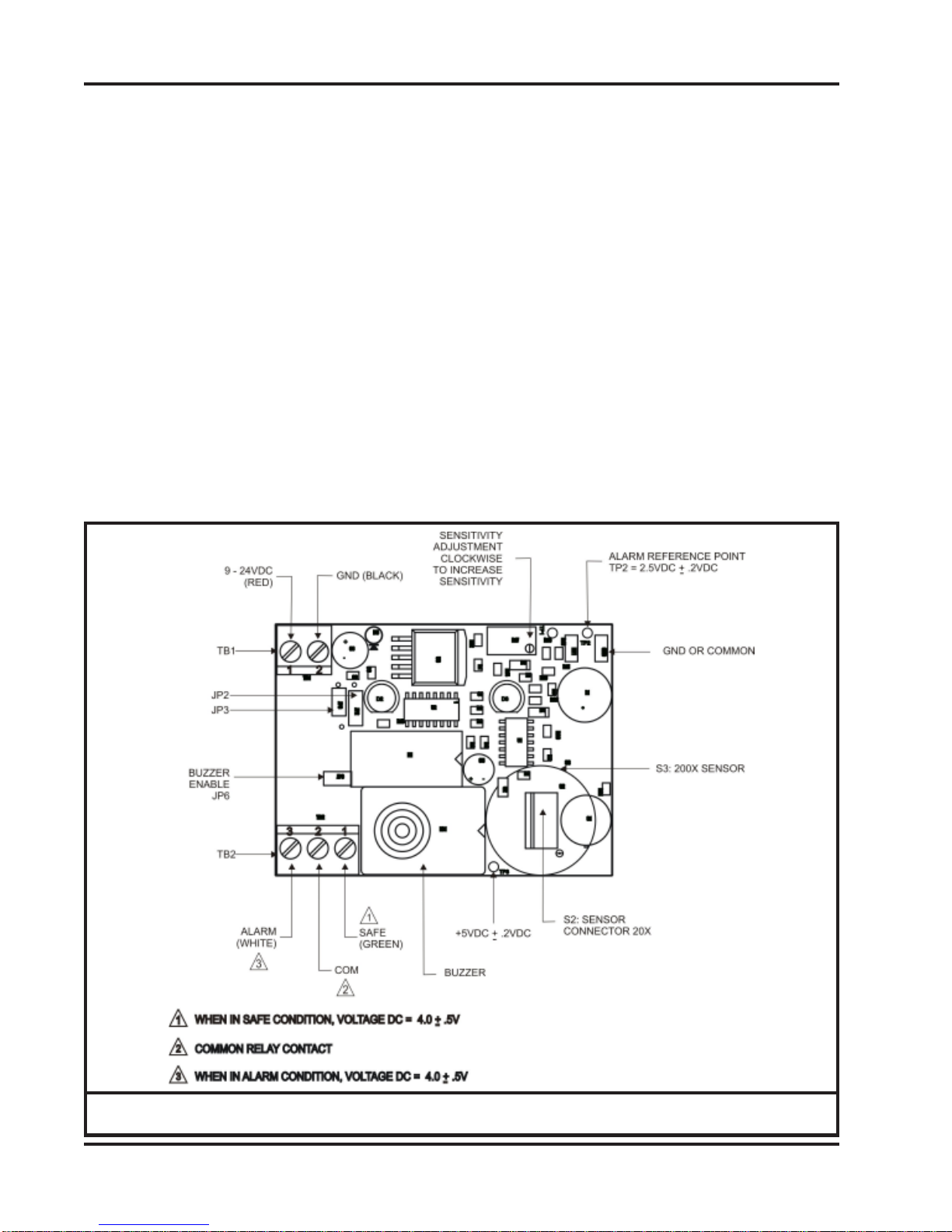
Sierra Monitor Corporation 2050-00 Applicability & effectivity User manual

GAS MONITORS
MODELS 2050-00 & 2050-10
MODELS 2060-00 & 2060-10

Applicability&Effectivity
Applicability& Effectivity
Sierra Monitor Corporation
1991 Tarob Court, Milpitas, CA 95035
(408) 262-6611
(800) 727-4377
E-Mail: sierra@sierramonitor.com
GAS MONITORS
MODELS 2050-00 & 2050-10
MODELS 2060-00 & 2060-10
APPLICABILITY & EFFECTIVITY
ThismanualprovidesinstructionsforthefollowingSierraMonitorproducts:
Model Description
2050-00 AmmoniaGas Monitor
2060-00 HalocarbonGas Monitor
Theinstructions are effectivefor the abovemodels as of January1, 2004
InstructionManualPartNumber: T10013
Rev C

Table of Contents
TABLE OF CONTENTS
SECTION PAGE
1.PRODUCTDESCRIPTION 1
1.1Introduction 1
1.2Application 1
1.3Configuration 1
1.4TemperatureRange 2
1.5 Sensor 2
1.6RemoteAlarm 2
2.QUICKSTART 3
2.1Overview 3
2.2 Wiring 3
3. OPERATION 4
3.1 Introduction 4
3.2Alarms 4
3.3Outputs 4
4.ALARM CALIBRATION 5
4.1FactoryAlarmCalibration 5
4.2FrequencyofAlarmCalibrationCheck 5
4.3Alarm Calibration Check Process 5
4.4Equipment Required 6
4.5Alarm Calibration Procedure 6
5. SERVICE
5.1Sensor Replacement 7
6. INSTALLATION 8
6.1GasSensorModuleLocations 8
6.2Mounting 8
6.3Wiring 8
6.4PowerSupply 8
6.5AlarmDevices 8
7.ALARM CONFIGURATION 10
8. SPECIFICATIONS 11
9.ACCESSORIES AND REPLACEMENT PARTS 11
10. LIMITED WARRANTY 11

Instruction Manual
Page: 2050/2060 Gas Monitors (5/04)
1.0 PRODUCTDESCRIPTION
1.1Introduction
TheModel2050 Ammonia and Model2060Refrigerant/
Halocarbon Gas Monitors are continuous duty, low cost
stationary monitors for detection of high levels (50-500
PPM) of ammonia and halocarbon ("freons") refrigerant
gases. See the specifications page for a full list of avail-
able applicable halocarbons
This manual provides instructions for both the 2050 and
2060 series Gas Monitors, including the relay versions.
1.2Application
These monitors are primarily used in and around freez-
ers,refrigerators,and compressor rooms to warnofleaks
and dangerous levels of these gases.
1.3Configuration
An alarm is activated when the concentration of gas
exceeds the user-adjustable level. An alarm condition
activates the alarm light on the front of the monitor and
generates an output signal. On Models 2050-00 and the
2060-00 the output signal a TTL (Transistor-Transis-
tor-Logic signal) can activate a remote alarm through
one of Sierra Monitor’sAlarm Panels. (The Model 2102
Dual Channel Alarm Panel can be connected up to 500
feet from the monitors. ) The models can be config-
ured with a 0.5 amp, dry contact relay.
The monitors are housed in a
polystyrene enclosure that is suit-
able for installation in freezer, re-
frigerator or other applications.
Test connections and adjustment
controls are located on the out-
side of the enclosure and are eas-
ily used, even when the operator
is wearing hand protection.
TheModel2050 Ammonia moni-
tor has a factory alarm setpoint of
100 ppm NH3. This setpoint is
user adjustible in the field over a
range of 50 to 500 ppm NH3. The
Model 2050 calibration can be
checked with Hydrogen gas.
The Model 2060 Halocarbon
monitor can be calibrated with
carbon monoxide and the factory
setpoint varies for the specific
type of halocarbon present. The
Model Gas TTL Relay
2050-00 Ammonia X X
2060-00 Halocarbons X X
Table 1.1 Gas Monitor Configurations
factory setpoint for R12 is 500 ppm while the setpoint
for R134 a is 50 ppm. See the specifications for more
details.
The Model 2050 / 2060 is cross sensitive to other com-
bustible gases. If combustible gasses in excess of 50
ppm are expected in the area please contact Sierra Moni-
tor to determine amount of cross-sensitivity expected
for the specific combustible gas. It is not recommended
to use this unit in areas with combustible gases present.
Figure 1.1 Outline View - 2050/2060 Series
1

2050/2060 Gas Monitors (5/04) Page:
Instruction Manual
1.4 Temperature Range
The Model 2050 and 2060 have temperature compen-
sated circuitry to provide stabilization in temperatures
rangingfrom-4oto158oF.
However, for optimum operation the unit should be cali-
brated at the normal temperature expected for the sensor
location.
1.5Semiconductor-TypeSensor
A solid-state semiconductor-type sensor and associ-
ated electronic circuitry ensure trouble-free, long-term
operation. All the electronic circuitry needed to operate
themonitor,except the DC input power,iscontained in a
compact unit. There are no pumps, filters, or chemical
cells to replace or maintain. Except for periodic calibra-
tion to verify the alarm setting, no attention is required
after installation. The user may adjust the alarm level by
applying a different calibration gas concentration.
A sensor self-check feature will flash the alarms on and
off alternatively should the sensor fail (open circuit).
The alarm flash includes LEDs, audible alarm, relay or
alarm signal as applicable.
1.6.RemoteAlarmAvailable
Ifaremote alarm is desired,SierraMonitor’sAlarm Pan-
els, the Model 2102 Dual ChannelAlarm Panels can be
connected up to 500 feet away from the monitors.
2

Instruction Manual
Page: 2050/2060 Gas Monitors (5/04)
3
2.0 QUICK START
2.1 Overview
TheGas Sensor Modulehas been supplied factory
calibratedand ready for immediate installationand
operation. An installer familiar with installation and
operation of gas detection products can use this
section to begin immediate use of the monitor.
2.2 Wiring
Each module requires four-conductor wiring (two
wires for power and two wires for the signal).
2.2.1. Model 2050-2060 Series
The Model 2050-2060 series are designed to
mount on any indoor vertical surface. Mount
the monitor in the desired location.
- The installation must meet any hazard-
ousenvironmentalcodesfor AC/DC elec-
trical instrumentation.
2.2.2 Wiring Connection
Terminalpositions on theelectronics board are
asfollows:
2.2.3 Start-up & Operation
To begin operation of the Gas Sensor Module
provide 9 - 24 VDC from a regulated power
supplysuch as one ofthe Sierra MonitorAlarm
Panels, 2102-XX. Each time the sensor mod-
ule is powered up it will perform a warm-up for
2 - 60 minutes.
During warm-up the monitor will, first, cycle
through safe/alarm/safe condition at one hertz.
Thiswill befollowed bya short periodof continu-
ousalarm beforewarm-up is completed.
2.2.4 Configuration
Thedefault configurationfor each moduleis to
operatewith a buzzerand a normally operating
open(NOO)relay.Theusercanchange thiscon-
figurationusing thejumpers provided.Refer to
table 6.2.
Terminal Function
TB1-1 + VDC (9 – 24)
TB1-2 GND (0VDC)
TB2-1 Relay NC (Normally Closed) or
Output to Model 2102 Safe
TB2-2 Relay Common
TB2-3 Relay NO (Normally Open) or
Output to Model 2102 Alarm
Table 2.1

2050/2060 Gas Monitors (5/04) Page:
Instruction Manual
4
3.0OPERATION
3.1 Introduction
Undernormalconditionsthegassensormoduledoes
notrequire operatoror technicianintervention. The
followingare conditionsunder whichthe modulere-
quiresattention:
- Routine periodic calibration
- Sensor replacement on a planned schedule
or when a sensor failure occurs.
- Periodic cleaning as necessary.
3.2 Alarms
Threealarm conditionsare possible. These canbe
detectedvisually atthe optionalSierra Monitorcon-
trollerand at the module.
Warm-Up Alarm
Oscillating (On/Off) contact closure and “red/
green”visualindication whenpower isfirst con-
nectedto themodule, followed bya continuous
closure of approximately 2-60 minutes indicat-
ingwarm-up.
Buzzer Relay Relay
Fail Safe
On/Off Oscilating Oscilating
Gas Alarm
Sustained contact closure and solid red light
(once the warm-up time is completed) indicat-
ingthepresence ofgasat, orabove,the pre-set
alarm limit.
Table2.1
Buzzer Relay Relay
Fail Safe
On Closed Open
Trouble Alarm
Interrupted contact closure and “red/green” vi-
sualindication (once the warm-up timeis com-
pleted)after unithas beenin operation, indicat-
ingeitherafailedsensororcalibrationproblems.
Buzzer Relay Relay
Fail Safe
On/Off Oscilating Oscilating
3.3 Outputs
For the non-relay configurations a 5 volt DC TTL
signal is provided to activate remote alarms such
asthe Sierra MonitorAlarm Panels. Relayconfigu-
ration alarm conditions described above are trans-
mitted to the annunciator as relay contact closures
fromthe monitor.
Thealarmoutputsare non-latchingclosedcontacts.
As soon as the gas concentration falls below the
alarm set-point, the alarm will stop and the alarm
output will cause the relay to de-energize and the
contactswill open.
During warm-up and failed sensor alarms the re-
lays contact and the display LED's oscillate at ap-
proximatelyone hertz.
=

Instruction Manual
Page: 2050/2060 Gas Monitors (5/04)
4.0ALARM CALIBRATION
4.1FactoryAlarmCalibration
Themodule hasbeen factorycalibrated toalarm as
indicated in Table 4.1 and as marked on the cali-
brationlabel shipped withthe module.
Model Time Gas cc/min
2050-XX 100sec. 100ppmNH350
2060-XX 60 sec. 500ppm R11 50
500ppmR12 50
50ppmR22 50
100ppmR113 50
70ppmR123 50
50ppmR134a 50
40ppmR141b 50
40ppmR142b 50
40ppmR500 50
70ppmR502 50
Table 4.1
4.2 Frequency ofAlarm Calibration Check
Themanufacturer recommends thatthe calibration
ofeach gassensor module beverified monthlydur-
ingthefirstthreemonths ofoperationandthenquar-
terly. More frequent checks are necessary during
periods of extreme humidity and temperature
changes. The monitor should have operated con-
tinuously (uninterrupted) for at least 24 hours prior
tocalibration adjustment.
4.3AlarmCalibrationCheckProcess
Theoutputsignalofthegassensormoduleiscalibrated
using a calibration gas mixture containing a known
concentrationofthegasofinterestandabalanceofair,
orusingasubstitutegas. Theconcentrationofthespan
gasmustbeequaltothealarmpointdesired.
Theequivalentsubstitutegasis80ppmHydrogen(H2)
forthe Model 2050and 150 ppmCarbon Monoxide
(CO)fortheModel2060.
Calibrationrequiresapplicationofthespangastothe
sensorandadjustmentofthesensitivityadjustmentpo-
tentiometer.
Warning:Duringcalibrationthealarmwillturnonand
remotealarms connectedto thealarm relayswill be
activated. Disable the remote alarm if necessary.
Fig. 4-1 Location of Calibration Voltmeter Connections and Adjustments
5

2050/2060 Gas Monitors (5/04) Page:
Instruction Manual
4.4EquipmentRequired
Thefollowingtoolsandequipmentwillberequiredfor
calibration:
-JewelersScrewdriver
-CalibrationGas
-Calibrationgasdeliverysystem
Foraccurate calibrationuse agas mixtureat there-
quiredconcentration mixedin anair balance,rather
thanwithaninert gaslikenitrogen. This gasandthe
requireddeliveryequipmentsuchastheModel1200-
26Calibrator isavailablefromSierraMonitorCorpo-
ration.
4.5AlarmCalibrationProcedure
1. Themonitorshould beinthesafecondition prior
tocalibration(greenLED“ON”).
- Besurethattheareaisnon-hazardousbe-
foreproceeding.
2. Withthemonitorinoperation,exposethesensor
toasample ofcalibration gas. Applycalibration
gasdirectlytothesensorinsuringthatthedelivery
cuplooselycoversthesensor. Use80PPMH2for
theModel2050 and150 PPMCO forthe Model
2060.
3. TheredLEDonthefaceofthemonitorshouldturn
"on".Ifthealarmoccurswithin18-20secondsand
stopswithinoneminuteoftheremovalofthecali-
brationgas, the monitoris in calibrationand re-
quiresnofurtheradjustment.
4. Ifthe monitorfails toalarm within90 secondsof
theapplicationofthegasadjustthepotentiometer
counterclockwiseuntilthealarmturns"on".
5. If the monitor fails to stop alarming within one
minuteoftheremovalofthegasadjustthepoten-
tiometerclockwiseuntilthealarmstops.
6. Afteradjustment,repeatsteps4and5toverifycali-
bration.
7. Whenthecalibrationis complete,reconnectany
alarmequipment as necessary.
6

Instruction Manual
Page: 2050/2060 Gas Monitors (5/04)
5.0 SERVICE
5.1 Sensor Replacement
Thegas sensor needsreplacement when:
- It is no longer possible to obtain correct
calibration
- The failed sensor alarm (oscillating
red/greenLED)ison
- The sensor output signal is noisy,
causingincorrectgasalarms.
Toreplacethesensor:
1. Confirm that the system power has been
removed.
Figure 5-1 Model 2050/2060 Electronics Board Connections
2. Remove thecover from the main enclosure.
3. Unplug the sensor connector on the lower
right hand corner of the electronics board.
4. Unscrewthesensorassemblyfromtheendofthe
enclosure.
5. Reversetheprecedingstepstoinstallthenewsen-
sorassembly.
6. Restorepowerandallowa minimumof24hours
forstabilizationbeforerecalibration. Thecalibra-
tionshouldbere-verifiedafter 6daysofcontinu-
ousoperation.
7

2050/2060 Gas Monitors (5/04) Page:
Instruction Manual
8
6.0INSTALLATION
6.1 Gas Sensor Module Locations
The gas sensor module is a diffusion type sensor
thatshouldbelocatedclosetotheanticipatedsource
or destination of the gas hazard. For heavy gases
such as H2S install the module within 24 inches of
theground. For lightergasessuch asCO andcom-
bustiblegases use ahigher elevation.
After optimum locations are determined based on
theabove recommendations, considerationshould
begiven to placingthe sensors inlocations that are
accessibleforcalibrationservice. Slightadjustments
to the location of the sensor may have little impact
on effectivity but major effect on accessibility.
6.2 Mounting
Tomount themonitor,removethe foursvrews inthe
cover plate and move the cover plate aside. Use
screws through the monitoring holes visible in the
four corners of the housing to mount the monitor to
awall.
- The installation must meed any hazardous envi-
ronmental codes forAC/DC electrical instrumenta-
tion.
6.3 Wiring
Interconnectwiringfromthe controllertothe module
is by 4 conductor 22 AWG (or lower AWG) cable,
conduit as necessary. Shielding is not required.
For installations where the distance from the con-
troller to the sensor is greater than 500 feet, 18
AWG cable is recommended.
The terminal strip on the electronics board in the
module. The wiring must be connected as indi-
cated in Figure 6.1 depending upon the controller
or relay configuration being used.
6.4 Power Supply
The power supplied by the controlling device or an
externalpowersupplymustmeetthefollowingspeci-
fications:
Voltage:9 - 24 VDC
Current:250mA
6.5Alarm Devices
Theinternalrelay isratedat 0.5Amp, normallyopen
dry contact rated at 100 VDC/130 VAC.
Terminal Function
TB1-1 + VDC (9 – 24)
TB1-2 GND (0VDC)
TB2-1 Relay NC (Normally Closed) or
Output to Model 2102 Safe
TB2-2 Relay Common
TB2-3 Relay NO (Normally Open) or
Output to Model 2102 Alarm
Table 6.1

Instruction Manual
Page: 2050/2060 Gas Monitors (5/04)
Figure6.1
InterconnectWiringTable
9

2050/2060 Gas Monitors (5/04) Page:
Instruction Manual
TB2-1 NC TB2-2 Common TB2-3 NO
No Power Open
Sensor Fail
Safe Open
Alarm Open
TB2-1 NC TB2-2 Common TB2-3 NO
No Power Open
Sensor Fail
Safe Open
Alarm Open
Table 6.3
Oscillating
Connected
Connected
Rela
y
O
p
eratin
g
States
Rela
y
O
p
eration
Normally Not Energized
Oscillating
Connected
Connected
Connected
Connected
Normally Energized - Fail Safe
Yes No
Default
Install Jumper
JP6 Remove Jumper
JP6
(Best for 20X)
TB1-1 TB1-2 TB2-1 TB2-2
+ DCV
(9-24 VDC) 0 DC
Common NC Common
Yes No Normally
Not Energized Normally
Energized
Default Default
Install Jumper
JP6 Remove Jumper
JP6
(Best for 20X)
N/A N/A
TB1-1 TB1-2 TB2-1 TB2-3
+ DCV
To Model 2102
Terminal J5 -2
or J6-2
0 DC
To Model 2102
Terminal J5 -3
or J6-3
Safe
To Model 2102
Terminal J5 -1
or J6-1
Alarm
To Model 2102
Terminal J5 -4 or
J6-4 Not Used
TB2-3
NO
Output Terminals TB2-2
Configuration Jumpers
Model 20X or 200X Configured with Alarm Relay Output
Wiring Terminations
Normally
Energized
Install Jumper
JP2 pins 2-3
Model 20X or 200X Configured for Interface to Model 2102 Alarm Panel
Power Supply
Buzzer Active
Model 2102
Power Supply
Jumper Configuration and Wiring Terminations
Relay Operation
Normally
Not Energized
Default
Install Jumper
JP2 pins 1-2
Output Terminals
Buzzer Active Relay Operation Interface Selection
Install Jumpers
JP3 pins 1-2
JP2 pins 1-2
Wiring Terminations
Table 6.2
7.0ALARM CONFIGURATION
10

Instruction Manual
Page: 2050/2060 Gas Monitors (5/04)
In all cases SMC’s responsibility and liability under this
warrantyshallbelimitedtothecostoftheequipment. The
purchasermustobtainshippinginstructionsfortheprepaid
returnofanyitemunderthiswarranty provisionandcom-
pliance with such instruction shall be a condition of this
warranty.
Exceptfortheexpresswarrantystatedabove,SMCdisclaims
allwarrantieswith regardtothe productssoldhereunder
includingallimpliedwarranties ofmerchantabilityandfit-
nessandtheexpresswarrantiesstatedhereinareinlieuofall
obligationsor liabilities onthe part ofSMC for damages
includingbutnotlimitedtoconsequentialdamagesarising
outof/orinconnectionwith theuseorperformanceof the
product.
8.0 SPECIFICATIONS
Indicators: GreenLEDfor Monitor “ON”/Safe
RedLED forAlarm
Sensor Type: Solid-state metal oxide semiconduc-
tor
AlarmSetpoint::
2050Series 100 ppmNH3
2060Series R11 500ppm
R12 500ppm
R22 50ppm
R113 100ppm
R123 70 ppm
R134a 50 ppm
R141b 40 ppm
R142b 40 ppm
R500 40 ppm
R502 70 ppm
User adjustable with calibration over
range of 50 to 500 ppm
Calibration Gas:
2050 Series 80 ppm Hydrogen (H2)
2060 Series 150 ppm Carbon Monoxide (CO)
Power: 9 VDC, 250 mA
Signal Output::
2050-00/2060-00 Nominal 5 volt DC, source 25 mA.
SAFE and ALARM Signals
0.5 AMP dry contact, 100 VDC, 130
VAC
Response Time: Less than 90 seconds
Operating Temperature Range:
-4oto 158oF(-20oto70oC)
Enclosure Material: Polystyrene
Size: 5.6x3.1x2.1in.
(14.2x7.9x5.3cm)
Weight: 0.3 lb(0.15 Kg)
9.0 ACCESSORIESAND REPLACEMENT PARTS
AlarmPanels
Model2102-00 Alarm Panel - 2 channel
Model2102-01 AlarmPanel-2channelwithaudible
CalibrationAccessories
1200-26 Gas Sensor Calibrator w/2 gas cylinders
(specify gas type/conc)
1290-10 Gas Cylinder - Carbon Monoxide 150 PPM
1290-11 Gas Cylinder - Hydrogen 80 PPM
Replacement parts
SPF22073 Sensor for 2050-XX
SPF22074 Sensor for 2060-XX
10.0 LIMITED WARRANTY
SIERRAMONITORCORPORATIONwarrantsitsproducts
tobefreefrom defectsinworkmanship ormaterialunder
normaluseandservicefortwoyearafterdateofshipment.
SMCwillrepairorreplace withoutchargeanyequipment
found to be defective during the warranty period. Final
determinationofthenatureandresponsibilityfordefective
ordamagedequipmentwillbemadebySMCpersonnel.
Allwarrantieshereunderarecontingentuponproperusein
theapplicationforwhichtheproductwasintendedanddo
notcoverproductswhichhavebeenmodified orrepaired
withoutSMC approval orwhich have been subjectedto
accident,impropermaintenance,installationorapplication,
or on which original identification marks have been re-
movedoraltered. ThisLimitedWarrantyalsowillnotapply
tointerconnectingcablesorwires,consumables(ie.calibra-
tiongases,batteries),nortoanydamageresultingfrombat-
teryleakage.
11
This manual suits for next models
3
Table of contents
Other Sierra Monitor Corporation Measuring Instrument manuals

Sierra Monitor Corporation
Sierra Monitor Corporation 5100-03-IT User manual

Sierra Monitor Corporation
Sierra Monitor Corporation 4400 User manual

Sierra Monitor Corporation
Sierra Monitor Corporation Sentry 5000 User manual

Sierra Monitor Corporation
Sierra Monitor Corporation Gas Sensor Monitors 201 User manual

Sierra Monitor Corporation
Sierra Monitor Corporation 3240-01 User manual