Model 5100-XX-IT Toxic Gas Sensor Module
Page 4 of 62
TABLE OF CONTENTS
Product Description...................................................................................................................... 7
1.1 General.........................................................................................................................................................7
1.2 Product Configuration ..................................................................................................................................8
1.3 Theory of Operation .....................................................................................................................................8
1.4 Modes of Operation......................................................................................................................................8
1.4.1 Sentry Interface.....................................................................................................................................8
1.4.2 Modbus Operation ................................................................................................................................8
1.4.3 Analog Operation..................................................................................................................................8
1.4.4 Remote Sensor.....................................................................................................................................8
1.4.5 HART Connection.................................................................................................................................9
1.4.6 Remote Alarm Reset.............................................................................................................................9
1.4.7 Optional Integral Relays........................................................................................................................9
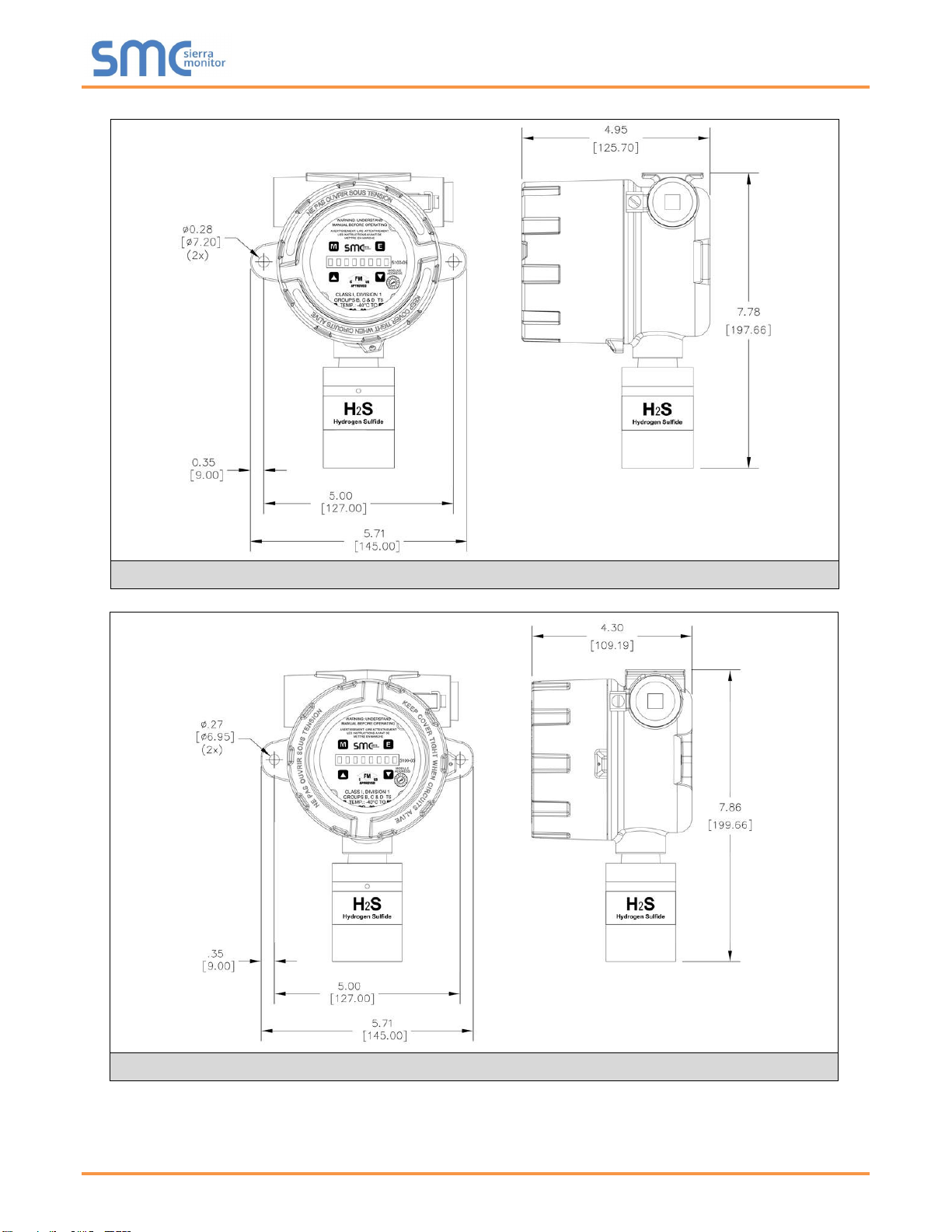
1.5 Mechanical...................................................................................................................................................9
1.5.1 Enclosure..............................................................................................................................................9
1.5.2 Transmitter Electronics.......................................................................................................................11
1.5.3 Sensor Assembly................................................................................................................................11
1.6 Interconnect Wiring ....................................................................................................................................11
1.7 Power Requirements..................................................................................................................................11
Cautions & Warnings.................................................................................................................. 12
2.1 Introduction.................................................................................................................................................12
2.2 Gas Sensor Modules –General.................................................................................................................12
2.3 Wiring Warnings.........................................................................................................................................12
2.4 Calibration Frequency................................................................................................................................12
Quick Start................................................................................................................................... 13
3.1 Overview ....................................................................................................................................................13
3.2 Wiring.........................................................................................................................................................13
3.3 Module Installation .....................................................................................................................................13
3.4 Transmitter Installation...............................................................................................................................13
3.5 Startup and Operation................................................................................................................................14
3.6Zero Stabilization .......................................................................................................................................14
Installation................................................................................................................................... 15
4.1 Sensor Module Locations...........................................................................................................................15
4.2 Wiring.........................................................................................................................................................16
4.2.1 Analog 4-20 mA Operation .................................................................................................................16
4.2.2 Modbus Operation Using RS-485 Connection....................................................................................16
4.2.2.1 Termination Resistor Jumpers.................................................................................................... 16
4.2.2.2 Bias Jumpers (BIAS A, BIAS B) ................................................................................................. 16
4.2.3 Sentry Operation Using Sentry Connection........................................................................................16
4.2.4 General ...............................................................................................................................................17
4.3 Enclosure Installation.................................................................................................................................17
4.4Transmitter and Sensor Installation ...........................................................................................................18
4.5 Module Address Switch..............................................................................................................................19
Operation..................................................................................................................................... 25
5.1 Introduction.................................................................................................................................................25
5.2 Data Entry Keypad.....................................................................................................................................25
5.3 Main Menu..................................................................................................................................................26
5.4 Set-Up........................................................................................................................................................27
5.5 Maintenance Sub-Menu.............................................................................................................................29
Calibration ................................................................................................................................... 30
6.1 Calibration Frequency................................................................................................................................30
6.2 Calibration Preparation ..............................................................................................................................30
6.3 Calibration Gas Delivery Methods..............................................................................................................30