SIG FOUR-STAR 60 User manual

1
FOUR-STAR 60 ARF ASSEMBLY MANUAL
INTRODUCTION:
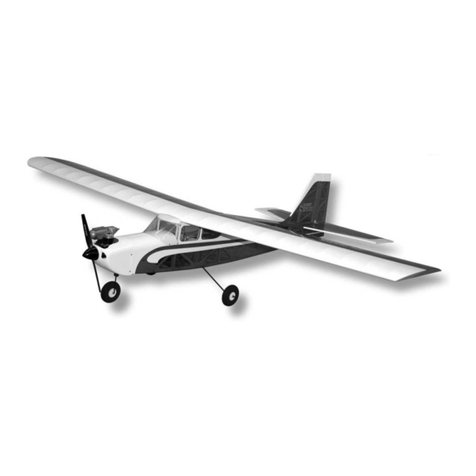
SIG’s FOUR-STAR 60 ARF combines the classic looks and
performance of Sig’s Four-Star series in an almost ready to fly
package. The FOUR-STAR 60 ARF is easy to fly and makes an
ideal choice for your first low wing airplane. Intermediate and
advanced flyers will love the maneuverability and smooth handling
of the Four-Star 60 ARF, making it the sport model you'll want to
take to the flying field every time.
Set the control throws at the suggested low rates for your first
flights, throttle back and enjoy a truly honest, gentle airplane. As
your skill level advances, dial-up the control throws a little to enjoy
a very aerobatic airplane. Inside and outside loops, rolls, inverted
flight, and snap maneuvers are all in the FOUR-STAR 60 flight
envelope.
The FOUR-STAR 60 ARF kit has been engineered to get you into
the air quickly as possible with an R/C model that will truly last.
The airframe has been expertly built and covered with AeroKote™.
This material is both rugged and easy to repair. The covering trim
scheme is provided on three large peel & stick mylar decal sheets.
This assembly manual has been specifically sequenced to get
your FOUR-STAR 60 ARF assembled and into the air very quickly.
We strongly suggest that you read through the manual first to get
familiar with the various parts and their assembly sequences. The
proper assembly and flying of this aircraft is your responsibility. If
you are new to the sport/hobby of radio control, we urge you to
seek the assistance of a qualified person to help you assemble this
model airplane. If you do not understand a particular assembly
step or sequence, do not guess - find qualified help and use it.
RADIO EQUIPMENT:
The FOUR-STAR 60 ARF requires a standard 4-channel radio
system and five standard servos. We have used and can highly
recommend both the Hitec™and Airtronics®systems. Both of
these very affordable and reliable radio systems offer all the
features you’ll need for this and the many other R/C aircraft in your
future. For reference, this assembly manual shows the installation
of a Hitec™radio system with standard servos. In addition, you will
need two aileron 12” servo lead extensions and a 6” aileron servo
Y-harness for connection to the receiver.
ENGINE SELECTION:
Engine choices for the FOUR-STAR 60 ARF are many. The
FOUR-STAR 60 ARF has been designed to produce excellent
performance when using the recommended engine sizes. Do not
use an engine larger than recommended.
2-stroke engines are a perfect choice to power your FOUR-STAR
60 ARF. Any plain-bearing or bearing equipped .60 to .75 sport
engine would be a good choice. For example, a great choice
would be the Irvine .61 engine. Like all Irvine engines, the .61 is
powerful, reliable, and quiet. Whatever engine you choose, take
the time to carefully break it in according to the manufacturer’s
instructions. A good running, reliable engine is a minimum
requirement for the enjoyment of this or any R/C model aircraft.
The FOUR-STAR 60 ARF can also use a variety of 4-stroke
engines. Any 4-stroke engine in the .65 - .90 displacement range
should provide plenty of power. An important thing to remember is
that typical 4-stroke engines have their throttle arms usually
located differently than throttle arms on 2-stroke engines. If you
want to power this model with a 4-stroke engine, you will likely
have to install a new, relocated throttle cable tube. While this is not
difficult, it is something to consider when choosing an engine.
COVERING MATERIAL:
Your FOUR-STAR 60 ARF has been professionally covered using
AeroKote™. This material is well known for its ease of application,
light weight, and consistency of color. If you live in a dry climate,
you may notice that some wrinkles might develop after removing
the covered parts from their plastic bags. This is perfectly normal
in low humidity climates. Your model was built and covered in a
part of the world with relatively high humidity and therefore the
wood was likely carrying a fair amount of moisture. When exposed
to drier air, the wood typically loses this moisture, dimensionally
“shrinking” in the process. In turn, this may cause some wrinkles.
However, wrinkles are easy to remove by just using a hobby type
heat iron.
R

2
We suggest covering the iron’s shoe with a thin cotton cloth, such
as an old T-shirt, to prevent scratching the film. The iron should be
set to about 220OF - 250OF (104OC - 121OC). Use the heated
iron to lightly shrink the material - do not press on it. Then, lightly
iron the material back down to the wood. You can also use a
hobby-type heat gun to re-shrink the covering but you must be
careful around seams or color joints. Re-heating seams may
cause them to “creep”, making them unsightly.
For part number reference, your FOUR-STAR 60 ARF was
covered in AeroKote™film with the following part numbers:
#SIGSTL311 Bright Red or #SIGSTL330 BrightYellow.
REQUIRED TOOLS:
For proper assembly, we suggest you have the following tools and
materials available:
A selection of glues - SIG Thin and Thick CA and
SIG Kwik-Set 5-Minute Epoxy
Threadlock Compound, Such as Loctite®
Non-Permanent Blue
Screwdriver Assortment
Pliers - Needle Nose & Flat Nose
Diagonal Wire Cutters
Small Allen Wrench Assortment
Pin Vise for Small Dia. Drill Bits
Hobby Knife With Sharp #11 Blades
Scissors
Heat Iron and Trim Seal Tool
Masking Tape
Paper Towels
Small Power Drill With Selection of Bits
Dremel®Tool With Selection of Sanding and Grinding Bits
A soldering iron and solder.
COMPLETE KIT PARTS LIST:
The following is a complete list of all parts contained in this kit.
Before beginning assembly, we suggest that you take the time to
inventory the parts in your kit.
BASIC AIRCRAFT PARTS:
❑1 each Fuselage
❑1 each Right & Left Wing Panel Set with Ailerons.
❑1 each Horizontal Stabilizer & Elevator Set.
❑1 each Vertical Fin & Rudder Set
WIRE PARTS:
❑1 each Formed Elevator Joiner Wire
❑1 each Formed Tailwheel Wire
❑2 each 2-56 x 1 1/4”Threaded Rods; servo end of elevator
& rudder pushrods
❑2 each 2-56 x 3 1/2”Threaded Rods; control surface end of
elevator & rudder pushrods
❑2 each 4-40 x 8”Threaded Rods; aileron pushrods
METRIC HARDWARE:
❑1 each M2 x 20mm Phillips Head Screw; for tailwheel
installation
❑2 each M2 Flat Metal Washers; for tailwheel installation
❑1 each M2 Hex Nut; for tailwheel installation
❑1 each 2mm I. D.Wheel Collar with set screw; for tailwheel
installation
❑1 each Allen "L" Wrench; for 2mm wheel collar
❑3 each M4 x 16mm Phillips Head Screws; for main landing
gear attachment
❑4 each M4 x 22mm Phillips Head Screws; for engine mount
attachment
❑2 each M4 x 30mm Phillips Head Screws; main wheel axles
❑2 each M4Hex Nuts; for axles
❑6 each M4Flat Metal Washers; (4) for engine mount
(2) for axles
❑2 each 4mm I. D.Wheel Collars with set screws; for axles
❑1 each Allen "L" Wrench; for 4mm wheel collars
❑4 each #2 x 8mm Phillips head washer style sheet metal
screws; for canopy
❑4 each Nylon "button" washers; for canopy
U.S. HARDWARE:
❑2 each 1/4-20 x 1-1/2”Nylon Wing Bolts; for wing mounting
❑1 each 2-56 x 3/4”Threaded Brass Coupler; for carb end of
throttle pushrod
❑3 each 2-56 Nylon R/C Links; for elevator (1), rudder (1),
throttle (1)
❑3 each 2-56 Solder R/C Links; for elevator (1), rudder (1),
throttle (1)
❑1 each Short, Right Nylon Control Horn; for aileron
❑1 each Short, Left Nylon Control Horn; for aileron
❑1 each Medium, Right Nylon Control Horn; for rudder
❑1 each Medium, Left Nylon Control Horn; for elevator
❑8 each #2 x 3/4”Sheet Metal Screws; for control horns
❑2 each 4-40 Metal R/C Links; for aileron (2)
❑2 each 4-40 Solder R/C Links; for aileron (2)
❑2 each 4-40 Hex Nuts; for aileron (2)
MISCELLANEOUS:
❑1 each 12mm Hardwood Front Wing Joiner
❑1 each 6mm Plywood Rear Wing Joiner
❑2 each 2mm Plywood Wing Hold-Down Plates
❑1 each 3mm Plywood Aileron Positioning Guide
❑1 each 3mm Formed Aluminum Main Landing Gear
❑1 each Molded Clear Plastic Canopy
❑1 set 4pc. Adjustable Engine Mounts, 60-size
❑22 each CA Hinges; for ailerons (12), elevator (6), rudder (4)
❑2 each 8.5cm dia. (approx. 3.35”) Main Wheels
❑1 each 30mm dia. (approx. 1.17”) Tailwheel
❑1 each Formed Metal Tailwheel Strap
❑1 each 2-1/2”dia. Spinner assembly
❑1 each 10mm sq. X 94mm Balsa; Fuel Tank Retainer
❑2 each 1cm x 8cm x 20cm Foam Rubber; for radio packing
❑1 each 2mm x 3.15mm x 26cm Plastic Throttle Pushrod
Tube
❑1 each 380cc (12.8 oz.) Plastic Fuel Tank with Hardware
❑1 each .065" O. D. x 18" Stranded Steel Cable - for throttle
pushrod

3
MISCELLANEOUS CONTINUED:
❑2 each .200 O. D. x .074 I. D. x 36”Inner Nylon Pushrods
Tubes for elevator and rudder
❑1 each Four-Star 60 ARF Assembly Manual
❑1 each Sig Four-Star 60 Fuselage Stars decal
❑1 each Sig Four-Star 60 Right Wing & Stabilizer Stars decal
❑1 each Sig Four-Star 60 Left Wing & Stabilizer Stars decal
ADDITIONAL ITEMS REQUIRED (NOT INCLUDED IN KIT):
❑4 each 6-32 x 1 1/2”Socket Head Screws
❑4 each 6-32 Lock Nuts
❑4 each No.6 Flat Washers
❑1 each 4 Channel Radio with 5 Standard Servos
❑2 each 12”Servo Extension cables
❑1 each 6”Aileron "Y" Harness
❑1 each .60 to .65 2-Stroke engine & Muffler
or .65 to .90 4-Stroke engine & Muffler
❑1 each Propeller to match engine used
❑2 each 9”Medium Silicone fuel tubing
ASSEMBLING THE WING:
The wing on the FOUR-STAR 60 ARF is designed as a strong,
easy to assemble one piece unit. For precise control there is one
servo mounted in each wing panel to control the ailerons. To avoid
unnecessary dents, dings, or scuffing of the various covered parts,
we suggest that you cover your workbench with a protective
blanket or foam sheet while assembling your model.
Installing the ailerons and aileron servos:
For the following steps you will need:
•1 each left and right wing panels (with ailerons & hinges)
•2 each standard servos
•2 each 12”servo extensions
•1 each 6”Servo “Y”Harness for your particular radio system.
❑1) The aileron servo bays are located on the bottom surface of
each wing panel. These bays have been covered over and now
need to be opened to allow access. Use a hobby knife to open the
aileron servo bay in one wing. To make the neatest possible job,
we suggest cutting each corner of the opening at a 45Oangle
toward the middle of the opening. Then, make a cut at the middle
of the opening, connecting it with the four previous corner cuts.
❑2) Use a covering iron to seal the four loose edges of each
side of the servo bay opening and trim the excess covering
material with a hobby knife.
Inside the servo bay opening you will see the plywood servo mount
and a short length of wood with a string tied to it. This string is
used to pull the aileron servo lead through the wing and out of the
opening in the top of each wing panel - leave it in place for now.
❑3) Also, on the top of each wing panel, just inboard of the
center wing rib, you will need to remove the covering from the
square opening. This is the servo lead exit. Inside this opening
you will see a piece of wood with a string tied to it. This is the other
end of the string in the aileron servo bay. Leave the string in place
for now.
❑4) Before installing the aileron servos you must attach an
extension cable to the aileron servo cable. The typical combined

4
length required is 21”.A12”extension cable will usually provide
sufficient length. Plug the extension cable into the servo and
secure well with tape. Also, install the mounting grommet and
eyelets onto the servo as described in the instructions that came
with your radio.
❑5) Pull the wooden block and line out of the servo bay
opening. Remove the wood from the line and discard it. Tie the
line securely to the connector end of the servo cable. Carefully
pull the line and servo cable through the wing until the servo cable
emerges from the opening in the top of the wing.
❑6) Fit the servo into the servo mount in the wing panel, (note
that the servo is positioned so that its output arm is at the forward
end toward the wing leading edge). Take up any slack in the servo
cable as you insert the servo by pulling on the end of the cable
where it exits the top of the wing. Use a pin vise and a small drill
bit to drill small pilot holes in the servo mount for the servo
mounting screws. Use the screws supplied with your radio system
to mount the servo securely in place on the servo mount. Repeat
this procedure to mount the servo in the opposite wing panel.
❑7) The ailerons are now hinged to the wing panels. The
installation process for these hinges is the same for all of the
control surfaces on this model. Press the six CA hinges into the
slots in the aileron. Use pins in the center of each hinge to keep
them centered when pressing them into the slots in the trailing
edge of the wing.
❑8) Carefully press the hinges into the trailing edge of the wing.
Adjust the aileron so that the tip of the aileron is flush with the wing
tip. The ailerons should be tight against the pins in the hinges to
minimize the gap between the wing and the aileron. The aileron is
now in the proper position for permanently gluing them in place
with thin CA glue.
❑9) Flex the aileron down and hold it into this position with a
piece of masking tape. Remove the pins from one hinge and apply
3-4 drops of thin CA glue to the hinge. We suggest using a fine
tipped applicator on the glue bottle to better control the flow of
glue.
❑10) When the glue is dry, you can repeat the gluing procedure
on the remaining five hinges. Remove the tape that is holding the
flexed aileron in position and flex the aileron in the opposite
direction and re-apply the masking tape to hold it in this position.
Now, apply 4-5 drops of thin CA glue to the bottom of each hinge
on the aileron. Remove the masking tape and return the aileron to
its center position. Because it takes a little time for the glue to fully

5
wick its way through the entire surface of the hinge and the
surrounding wood, allow 10 minutes before flexing the aileron.
Any spilled glue can be removed with Sig Debonder.
After sufficient time has passed, flex the aileron up and down
several times to create free and easy movement. You must also
pull on the aileron at each hinge location to be sure that the hinges
are firmly bonded in place. Repeat this process to attach the
aileron to the other wing.
Installing the ailerons, horns, and pushrods:
For the following steps you will need:
•2 each 4-40 x 8”Threaded Rods
•2 each 4-40 Metal R/C Links
•2 each 4-40 Solder R/C Links
•2 each 4-40 Hex Nuts
•1 each Short Right Nylon Control Horn
•1 each Short Left Nylon Control Horn
•4 each #2 x 3/4”Sheet Metal Screws.
❑1) We recommend using servo output arms for the aileron
servos. Install the arms to the two aileron servos so that when
they are in neutral the arms are pointing toward the center of the
wing (towards the fuselage). The arms should be at 90Oto the
servo when the aileron control stick on the transmitter is in neutral
and the transmitter trims are in neutral as well.
❑2) Screw one of the 4-40 hex nuts all of the way onto one of
the 8”4-40 threaded pushrods. Now, thread one of the 4-40 Metal
R/C Links onto the pushrod so that about 3/8”of the threads on the
rod are showing past the barrel of the connector.
❑3) Attach the 4-40 link and pushrod to the second to last hole
in the aileron servo output arm. Position the pushrod so that it is
90Oto the aileron hinge line. Use a felt tip pen to mark the pushrod
location on the trailing edge of the wing just ahead of the aileron.
❑4) Swing the pushrod out of the way and locate the control
horn. There are a left and right horn and the base of the horn
should point toward the inboard (fuselage) end of the wing.
Set the control horn on the bottom of the aileron. The upright arm
of the horn should be parallel with the servo and should line up
with the pushrod pen mark on the wing to establish the proper left
to right position. Now, the horn should be moved forward or aft
until the linkage holes in the upright arm are directly over the hinge
line.
❑5) Use a 1/16”drill bit to drill through the aileron for the control
horn screws. Use two of the #2 x 3/4”Sheet Metal Screws to
attach the control horn to the wing by screwing them into the two
holes in the nylon retaining plate that is molded with the horn. The
aileron should be sandwiched between the control horn on the
bottom and the retaining plate on the top. After the screws are
securely tightened, the excess screw that is extending past the
retaining plate can be cut off with a pair of side cutting pliers.
3/8”

6
❑6) Place the 4-40 Solder R/C Link into the last hole in the
control horn. Swing the aileron pushrod against the control horn.
Make sure that the servo is still in the neutral position and tape the
aileron into approximately neutral position. Hold the pushrod
against the 4-40 Solder R/C Link. Mark the pushrod wire 3/16”
beyond the end of the center barrel of the solder link.
NOTE: Depending on the type of servo that you use, you may
have to bend the pushrod slightly in the middle to angle it up from
the wing so that it is aligned with the control horn without putting
any bending force on the servo arm.
❑7) Remove the pushrod from the servo and remove the solder
link from the control horn. Cut the pushrod at the mark. Slip the
solder link onto the end of the pushrod so that the end of the rod
extends 3/16”beyond the barrel on the link and solder into
position, using enough heat to “sweat”the joint completely.
❑8) Reattach the pushrod to the servo and the control horn.
The aileron should be approximately neutral. Final adjustment will
come later. Now fabricate and install the opposite pushrod and
control horn assembly the same way.
Joining the Wings:
For the following steps you will need:
•Both wing panels
•1 each 12mm Hardwood Front Wing Joiner
•1 each 6mm Plywood Rear Wing Joiner.
❑1) Slide the front and rear wing joiners into one of the wing
panels and then, slide the other wing panel into position to test the
fit of the joiners. The wings should fit tightly together and the
center ribs should fit flush around their edges. If you need to make
any adjustments to get the proper alignment you may slightly trim
the openings in the wing ribs.
❑2) Use Sig Slow Cure epoxy to join the two wing panels
together. Apply the glue generously to the end ribs, Work some
glue into the joiner slots and coat the joiners. Carefully slide the
wing halves into place and hold them in the proper alignment with
tape until the epoxy cures. Wipe away any excess epoxy that
oozes from the center joint with a paper towel or a rag dampened
with isopropyl alcohol before the glue cures. Be careful that the
leading and trailing edges of the two wings are perfectly aligned
and that there is no built in twist.
Fitting the Wing to the Fuselage:
For the following steps you will need:
•The assembled wing
•The fuselage.
•2 each 1/4-20 x 1-1/2”Nylon Wing Bolts
•2 each 2mm Plywood Wing Hold-Down Plates
❑1) Place the plywood wing hold down plates on the bottom of
the wing. The 1/4”holes in the plates should line up with the holes
in the wing panels. The rear edges should be flush with the wing
trailing edge and they should be centered on the wing joint.
Carefully draw around the plywood plates with a felt tip pen to mark
their location on the wing covering. Lift the plates from the wing.
3/16”

7
❑2) Carefully remove the covering from the bottom of the wing
at the location of the plywood plates by using a sharp knife to cut
the covering approximately 3/32”inside the drawn lines and
remove the covering from the wing.
❑3) Use Medium CA to glue the plywood plates to the bottom of
the wing. Now mount the wing onto the fuselage and install the
nylon bolts through the wing and into the blind nuts installed in the
fuselage. Now remove the wing and bolts and set them aside until
later.
ASSEMBLING THE FUSELAGE:
Preparing The Fuselage:
For the following step you will need the fuselage.
The fuselage has been built and covered but there are several
openings that must now be opened up. These are:
1 - Stabilizer & Rudder openings...Located at rear of
fuselage
2 - Antenna Exit opening...Located on the bottom rear
of fuselage
3 - Three screw holes for mounting landing gear...Located
on the bottom of the fuselage just ahead of the wing
opening.
4 - Engine compartment drain hole...Located on the
bottom of the fuselage just ahead of the firewall.
Installing the Main Landing Gear
For the following step you will need:
•The Fuselage
•1 each Formed Aluminum Main Landing Gear
•2 each M4 x 30mm Phillips Head Screws
•2 each M4 Hex Nuts
•2 each M4 Flat Metal Washers
•2 each 4mm I. D. Wheel Collars with set screws
•1 each Allen "L" Wrench
•3 each M4 x 16mm Phillips Head Screws.
Note: When assembling the hardware in the following steps you
must use a thread-locking compound such as Locktite #242.
❑1) Slip one M4 washer onto each M4 x 30mm Phillips Head
Screw. Insert the screws into the axle holes at the bottom of the
landing gear legs, from the inside surface. Thread one M4 hex nut
onto the threads of each screw, all of the way up to the
Antenna exit
Pushrod exit
Gear Screw Holes
Drain Hole

8
aluminum landing gear. Use a phillips screw driver and a small
wrench to firmly tighten the nuts to the screws on the landing gear.
❑2) Now, slide the main wheels onto the axle screws. The
dished side of the wheel hub should face out. Place the M4 wheel
collar onto the axle. Leaving just a little play for the wheel, tighten
the wheel collar set screw with the allen wrench provided.
❑2) The entire landing gear assembly is now mounted onto the
bottom of the fuselage using the three M4 x 16mm Phillips Head
Screws.
ENGINE AND FUEL TANK INSTALLATION:
The 380cc (12.8oz.) fuel tank supplied with this kit is easily
assembled. We suggest using a simple two line fuel system in this
airplane. One fuel line is connected to the "clunk" or fuel pick-up
line and the engine's carburetor. This same line will also be used
to fill the tank. The second line is the overflow line for use when
filling the tank. After filling the tank, this same line is then
connected to the engine's muffler pressure nipple, providing
muffler pressure to the tank. Note that the rubber stopper for the
tank has two holes all the way through it. Use these holes for the
two fuel lines. Gently bend the aluminum overflow tube upwards
to 90O, to reach the top of the tank. Adjust the length of the
internal silicon fuel tubing to allow free movement of the fuel
pick-up inside the tank. Install the stopper assembly into the neck
of the tank and secure by tightening the compression screw.
ENGINE INSTALLATION:
This instruction sequence will install both the fuel tank and the
engine. Therefore, you will need the following:
•The Engine (with muffler removed) - not included
•The Assembled Fuel Tank
•1 each 10mm sq. x 94mm balsa strip
•1 each Motor Mount Assembly (4-piece)*
•4 Each M4 x 22mm Screws
•4 Each M4 Washers
•2 Each 9" Lengths of Silicon Fuel Tubing - not included
•4 Each 6-32 x 1 1/2" Socket Head Screws - not included
•4 Each 6-32 Lock Nuts - not included
•4 Each #6 Washers - not included
(*NOTE: The motor mount system provided in the kit can be used
in two ways - with or without the adjustable bases. The two bases
can be used when you need a little more mounting arm length for
your engine. This could be the case when working with larger
4-stroke engines. However, typical 2-stroke engines do not need
this extra length. In this case the mounting bases can be set aside
and not used.)
NOTE: If you are using a 4-stroke motor, please skip ahead to
step #6 in this section for special instructions relating to 4-stroke
installation.
❑1) The fuel tank is installed first. Apply a bead of silicon sealer
around the neck of the fuel tank and install it into the fuel
compartment, aligning the neck with the round hole in the firewall.

9
Press the neck into the firewall hole. Allow the silicon sealant to
cure before applying any pressure to the fuel lines.
❑2) Glue the 10mm sq.x 94mm balsa strip into position against
the fuselage sides and against the rear of the fuel tank. Trim as
required to obtain a tight fit against the fuselage sides.
NOTE: The engine compartment was fuel proofed during
production of the airplane. However, for a little extra insurance,
you could give the engine compartment an additional coat of
surfacing resin. If you decide to do this, use a brush to apply the
resin and be sure to brush the resin up to the covering edges.
❑3) Apply a little thread-locking compound to the four
M4 x 22mm screws and install the two motor mount arms to the
firewall - do not tighten in place yet. As mentioned earlier, these
arms can be positioned to adjust to the width of the engine's
crankcase. Place your engine on the motor mount arms and move
the arms as needed to accept the engine. Also, center the engine
to the fuselage in the top view. When everything appears correct,
tighten the screws, securing the mounts to the firewall.
❑4) Use a punch or pencil to mark the engine's mounting screw
locations directly onto the motor mount arms. Remove the engine
and drill the four required holes in the mounts for your engine. If
you are using 6-32 x 1 1/2”screws and lock nuts (not supplied) to
mount your engine, use a 5/32" dia. bit for the clearance holes. Do
not drill and tap these motor mounts. Doing so may weaken them.
Use a little thread-locking compound on all screws when
assembling these components. The muffler should be mounted
after the throttle linkage has been made in the following section.
❑5) Some engine configurations have rear-mounted, remote
needle valve assemblies. If you are using this type of engine, you
will have to likely drill a hole in the side of the fuselage to allow the
needle valve to clear. Be sure to fuel proof any exposed wood in
such holes with epoxy resin, clear dope, etc.
4-STROKE INSTALLATION DETAILS:
Note: If you are using a two stroke motor you may move on to the
next section of the instructions.
❑6) When using a 4-stroke motor you will have to relocate the
throttle pushrod housing to fit your installation. Remove the
housing from the fuselage now.
❑7) Apply a little thread-locking compound to the four
M4 x 22mm screws and install the two motor mount arms to the
firewall - do not tighten in place yet. As mentioned earlier, these
arms can be positioned to adjust to the width of the engine's
crankcase. Place your engine on the motor mount arms and move
the arms as needed to accept the engine. Also, center the engine
to the fuselage in the top view. When everything appears correct,
tighten the screws, securing the mounts to the firewall.
❑8) Install a Servo Connector (not included) onto the throttle arm
on your motor. Set your motor into position and mark the firewall
with the new location of the throttle pushrod.
Now, remove the motor and drill a 1/8”hole in the firewall at the
marked location. You will also need to drill a new hole in the
fuselage frame that is at the front of the wing if the new location on
the firewall is on the opposite side than the factory installation. The

pushrod housing should be glued into position in the holes in the
firewall and former.
❑9) Now install the motor as described in step #4 of this section.
❑10) Now install the fuel tank as described in steps #1 & #2 of
this section.
TAIL SURFACE INSTALLATION:
For the following step you will need:
The Fuselage
•1 each Horizontal Stabilizer & Elevator Set.
•1 each Vertical Fin & Rudder Set
•1 each Formed Elevator Joiner Wire
•1 each Formed Tailwheel Wire
•1 each M2 x 20mm Phillips Head Screw
•2 each M2 Flat Metal Washers
•1 each M2 Hex Nut
•1 each 2mm I. D. Wheel Collar with set screw
•1 each Allen "L" Wrench; for 2mm wheel collar
•10 each CA Hinges; elevator (6), rudder (4)
❑1) Prepare the fuselage to receive the horizontal stabilizer and
vertical fin. At the front of the stab platform, underneath the
covering material, are 2 balsa tail fairing blocks. The tail fairing
blocks are supported (to prevent shipping damage) by extra
spacer blocks, also underneath the covering. These spacer blocks
must be removed to allow installation of the stabilizer and fin.
a) Mark the positions of
the stab and fin on the
fuselage. Both the stab and
fin are 3/8”thick, so make
the marks 3/8”wide.
b) Remove the covering
material between the marks
to reveal the spacer blocks
that must be removed.
c) Cut the spacer
blocks loose with a #11
knife. Slide the spacer
blocks out, leaving the two
covered tail fairing blocks
attached to the fuselage.
d) The remaining tail
fairing blocks should be
handled carefully until the
stabilizer and fin are
permanently glued in place
in later steps.
❑2) Prepare to install the elevator joiner wire into the inboard
leading edges of both elevator halves. Start by first removing a
strip of covering material over the channel and hole that are
already in the leading edges of the elevators for the joiner wire.
Trial fit the joiner wire. Make any small alertations for proper fit.
❑3) Use a toothpick or small dowel to apply epoxy into the
elevator joiner holes and channels in each elevator half. Press the
wire elevator joiner into each elevator half and lay the assembly on
a flat work surface, protected with waxed paper. Wipe off any
excess glue with a paper towel and alcohol. Make sure the leading
edge of the entire elevator assembly is straight, so that it will mate
up properly against the back of the stabilizer. Allow the epoxy to
cure completely before continuing.
❑4) Use a felt tip pen and a small square to mark the centerline
on the top of the stabilizer.
❑5) Test fit the horizontal stabilizer in place into the rear of the
fuselage. Position the stab accurately and make any final
adjustments that might be needed. We have found it helpful
to attach the wing panels to the fuselage before gluing the stab in
place. This provides a good visual aid when checking the stab for
level and also for being square to the wings in the top view. Slip
the stab in place, being careful to align it squarely and that the slot
at the rear of the stab is aligned with the fuselage sides. With the
fuselage on a flat surface, sight the model from the front. The stab
should be absolutely aligned with the wings, without leaning to one
side or the other. If it is leaning, use a small weight or a little
masking tape to straighten it out.
10

11
❑6) Now use a felt tip pen to mark the position of the fuselage
onto the bottom of the stabilizer. You will also want to mark the
location of the tail fairings on the top of the stabilizer. Remove the
stabilizer from the model.
❑7) You must now carefully remove the covering from the
stabilizer in order to expose the wooden structure for gluing. The
covering should be trimmed away 1/16”inside the drawn lines. It
is extremely important that you cut the covering only and not the
balsa underneath. Do not cut into the balsa.
❑8) The horizontal stabilizer is now glued in place into the rear of
the fuselage. We suggest using 5-minute epoxy for this job to
allow time to position the stab accurately and make any final
adjustments that might be needed. Allow the glue to set
completely.
❑9) The elevators are now hinged to the stabilizer. Use the
same hinging method described earlier in Step 8 of the WING
ASSEMBLY instructions.
❑10) Place the fin into position on the fuselage. Use a felt tip pen
to mark the position of the fin onto the top of the stabilizer. You will
also want to mark the location of the tail fairings on the side of the
fin. Remove the fin from the model.
❑11) You must now carefully remove the covering from the
stabilizer and fin in order to expose the wooden structure for
Bottom
Top
XX

12
gluing. The covering should be trimmed away 1/16”inside the
drawn lines. It is extremely important that you cut the covering
only and not the balsa underneath. Do not cut into the balsa. Also
remove the covering from the sides of the fin in the location of the
tail fairings.
❑12) The vertical fin is now glued in place into the rear of the
fuselage - use 5-minute epoxy for the job to give you a little
working time. Apply glue to the exposed wood on both sides of the
fin base and to the bottom of the fin where it contacts the stab.
Also apply glue to the fin tailpost, where it slips into the rear of the
fuselage - keep glue away from the elevator hole in the tailpost.
With the fin in place, sight the model from the front to make sure
the fin is absolutely 90Oupright to the stab. If needed, use a little
masking tape to pull it into alignment. Wipe off any excess glue
using alcohol.
❑13) The tailwheel assembly is now prepared and attached to
the bottom of the rudder. From the kit contents you will need:
•1 each pre-bent tailwheel wire
•1 each 2mm wheel collar
•1 each metal tailwheel wire bracket
•2 each M2 washers
•1 each M2 x 20mm screw
•1 each M2 hex nut
•1 each 1" dia. tailwheel
•1 each Allen wrench for the wheel collar.
❑14) The tailwheel has two dissimilar sides - one side of the hub
is "dished" inward and the other side has its axle hole flush with
the hub. For mounting purposes, the "dished" side faces the wheel
collar. Simply slip the wheel in place onto the axle of the pre-bent
tailwheel wire, followed by the wheel collar. Leave a little play in
the wheel and use the Allen wrench to tighten and secure the
wheel collar to the axle. A little thread-locking compound on the
set screw will keep it firmly in place.
❑15) The tailwheel assembly is now mounted to the bottom front
of the rudder. Use your hobby knife to remove the covering from
the slot in the bottom of the rudder.
❑16) Insert the upright tailwheel wire stub into the hole and slot.
Slip the metal tailwheel bracket over the wire onto the bottom front
of the rudder. Mark the location of the hole in the bracket onto one
side of the rudder. Remove the bracket and use a 1/16" dia. bit to
drill through the rudder at the mark just made. Place the tailwheel
wire back onto the rudder and slip the bracket in place, aligned
with the hole just drilled. Place a washer onto the 14mm screw
and slip it through the bracket and out the other side of the rudder.
Use the remaining washer and hex nut to tighten the assembly
firmly to the rudder. Now, apply thin CA glue to the slot to lock the
wire into position and to harden the balsa wood in this area.
❑17) The rudder is now hinged to the vertical fin. Use the same
hinging method described earlier in Step 8 of the WING
ASSEMBLY instructions.
RADIO INSTALLATION:
❑1) Because the aileron servos are already installed and ready,
the installation of the rest of the radio system only consists of
dropping in the rudder, elevator and throttle servos, the receiver,
battery pack, and the switch. The pushrod connections to these
servos will be made shortly. Install the rubber grommets and
eyelets supplied with your radio system onto the rudder, elevator,
and throttle servos. Install all three servos in place into the
fuselage servo tray, again using the screws supplied with your

13
system. We have found it handy to label these leads for easy
identification when plugging them into the receiver.
❑2) The on/off switch should be mounted on the fuselage side
opposite of the engine exhaust. You must cut a small rectangular
slot for the switch body and mount it with the hardware supplied
with the radio system.
❑3) The receiver is now mounted in place. First, feed the
receiver's antenna through the internal antenna tube (it exits at the
bottom rear of the fuselage). The receiver is wrapped in one of the
pieces of foam rubber and placed in the fuselage just ahead of the
servos. Use the remaining piece of foam rubber to pad your
airborne battery pack. Wrap the pack securely with the foam and
slide it forward under the fuel tank. The final location of the battery
pack will be determined during final balancing.
PUSHROD ASSEMBLY & CONNECTION:
From the kit contents locate the following:
•2 each .20" O.D. x 36" nylon rudder and elevator pushrods
•1 each .065" dia. x 18" braided throttle cable
•2 each 2-56 x 1 1/4" rods, threaded one end - rudder and
elevator servo control rods
•2 each 2-56 x 3 1/2" rods, threaded one end - rudder and
elevator control horn rods
•3 each 2-56 solder links
•3 each 2-56 nylon R/C links
•1 each 2-56 x 3/4" threaded brass coupler for the throttle
•1 each Medium, Right Nylon Control Horn; for rudder
•1 each Medium, Left Nylon Control Horn; for elevator
•4 each #2 x 1/2" pan head screws - control horn attachment
You will also need three servo output arms for your servos and be
sure your radio system is charged and ready to use for this
section.
❑1) Use your soldering iron to solder the 2-56 x 3/4" brass
coupler onto one end of the braided throttle cable. Next, solder the
unthreaded ends of the two 1 1/4" rudder and elevator servo
control rods into two of the 2-56 solder links.
❑2) Insert the unthreaded end of the 3 1/2" control rod into one
of the 36" nylon control tubes, up to the threads on the rods.
Thread the rod into the tube about 3/16" - 1/4". Repeat this
procedure with the remaining tube and rod. Thread a nylon R/C
link onto the exposed threads of each rod - these are the ends that
will be attached to the rudder and elevator control horns.
❑3) Start with the rudder pushrod. Looking at the fuselage from
the rear, the rudder pushrod exit is on the left side. Attach the
control horn to the nylon R/C link. Slip the unprepared end of
the nylon control tube into the pushrod exit at the rear of the
fuselage on the left side. Push the rod all the way into the radio
compartment. Hold the nylon control horn in place against the
rudder at its leading edge, lining up the holes in the horn with the
hinge line of the rudder. Use a pencil to press indentations into the
rudder covering through the two screw hole locations on the base
of the horn.
❑4) Remove the nylon pushrod from the fuselage and remove
the control horn from the R/C link. Use a 3/32" dia. bit to drill two
holes through the rudder at the marks just made. Press two #2 x
1/2" screws through the base of the rudder horn and the holes in
the rudder. Hold the nylon base part to the opposite side of the
rudder and secure the horn in place with a screwdriver.
❑5) The nylon elevator control horn is mounted to the bottom of
the right elevator half (when viewed from the rear) in the same
manner as the rudder horn. Note that the elevator horn is angled
slightly inward toward the fuselage to line-up with the pushrod exit.
Install both the rudder and elevator pushrods into their exits from
the rear of the fuselage and snap the R/C links in place to the
nylon horns.
❑6) The pushrod connections are now made for the rudder and
elevator servos. Begin by neutralizing the rudder and holding in
this position with masking tape.
Turn the radio system on and center the rudder and elevator

14
transmitter trims. Trial-fit the servo arms onto the servos until you
find a spline location that places one of the arms at 90Oto the
servo body. We suggest clipping off the other three arms to avoid
any potential mechanical interference. Press the servo arms in
place.
Press one of the solder links into the outermost hole in the rudder
servo arm, alongside the nylon pushrod. With the solder link and
pushrod tube in this relationship, use a marker pen to make a mark
on the nylon tube for cutting the tube to final length. This length
must leave enough tube to thread the stud end of the solder link
into it about 1/2" or so. Cut the tube with your hobby knife at the
mark just made.
Thread one of the solder link/studs into the end of the trimmed
nylon rudder pushrod. Connect the solder link to the servo output
arm. Adjust the rear nylon R/C link as needed to set the rudder at
neutral. Repeat this process for the elevator servo connection.
❑7) The throttle pushrod is next. Thread the remaining 2-56
nylon R/C link onto the threaded brass coupler that is soldered to
one end of the braided throttle cable. From the firewall side, insert
the braided throttle cable into the tube housing, pushing it into the
radio compartment. Turn the radio system on and make sure the
servo is traveling in the right direction for low and high throttle. Set
the throttle stick to full low throttle, with the trim lever centered.
Push or pull the throttle cable to close the carburetor on the
engine. Connect the remaining solder link to the throttle servo
output arm. Use a marker pen to mark the cable for cutting, with
sufficient length to fit into the solder links' tube end for the required
solder connection.
❑8) Remove the cable and cut it at the mark just made (use a
carbide cut-off wheel for this cut) and reinsert it back into the
throttle housing tube in the face of the firewall. Solder the link in
place to the trimmed end of the cable. Connect the solder link to
the servo output arm and the nylon R/C link to the carburetor
throttle arm. Use the radio to test the throttle action and adjust as
needed to obtain true "low" and "high" throttle movement without
any binding.
❑9) Assemble the wings to the fuselage in preparation for
adjusting the ailerons to neutral. Your kit includes a special shaped
plywood piece called an Aileron Position Guide (APG) that allows
you to precisely measure the neutral position of each aileron - see
picture below of APG in use. Hold the APG tight against the
bottom of the wing panel at the trailing edge. Adjust the length of
the aileron pushrod until the bottom surface of the aileron is
parallel with the rear of the APG. After the aileron pushrods are
adjusted the 4-40 hex nut must be tightened against the end of the
metal link.
❑10) After the flight surfaces have been neutralized, take the
time to fit each R/C link with a short length of fuel tubing (medium
silicon tubing is fine for 2-56 hardware) to keep the links firmly in
place to each control horn and servo arm. This common safety
practice has saved a lot of models! Last, make sure that you have
secured the servo arms to each servo with the retaining screws.
SPINNER ASSEMBLY:
❑1) Locate the black SIG spinner assembly from the kit
contents. This spinner is easy to install, lends a great look to your
finished FOUR-STAR 60 ARF and is ready for use with APC
propellers! Choose the correct adapter ring for your engine.
❑2) The fit should be a nice slip fit over the engine's prop shaft.
Slip the spinner back plate onto the prop shaft and onto the

15
adapter ring. The propeller is installed next, followed by the nose
cone. The cone is held in place with the provided screws. Be sure
to snug the screws securely in place, but do not over-tighten them.
Install the muffler onto the engine and connect the fuel tank vent
line to the pressure outlet on the muffler.
CANOPY INSTALLATION:
❑1) Press the four silicon washers into the four pre-drilled
holes in the canopy (from experience, do not drop these washers
on the floor because they are really hard to find!). Place the
canopy into position. Carefully center the canopy and use a few
pieces of masking tape to hold it in this position. Use a pin through
each washer's center to poke a small hole at each location.
Remove the tape and the canopy.
❑2) Press the silicon washers onto each screw. Use a
screwdriver to insert each screw in place through the canopy and
into the holes just made. Tighten the screws enough to force the
small diameter side of the washer into the holes in the canopy - do
not over tighten, it is not necessary.
CONTROL SURFACETRAVEL CHART:
There are any number of different radio systems currently in use
and on the market. Because of this, it is not possible to explain the
optimum set-up for all systems for this particular airplane. The
following suggested control surface travel information is based
on our experience with the FOUR-STAR 60 ARF. These
suggested surface movements should be considered as starting
points. As your experience and confidence builds, control
movements can be adjusted to suit your particular style of flying
and to explore the airplane's capabilities.
SURFACE LOW RATE TRAVEL HIGH RATE TRAVEL
ELEVATORS: 3/4” UP - 3/4” DOWN 1" UP - 1" DOWN
AILERONS: 5/8” UP - 5/8” DOWN 7/8” UP - 7/8” DOWN
RUDDER: 1” LEFT - 1” RIGHT 1 1/4” LEFT - 1 1/4” RIGHT
THROTTLE: FULL RANGE OF TRAVEL
NOTE: These measurements were taken as follows:
• Elevator travel measured at the widest inboard trailing edge
• Aileron travel measured at the inboard trailing edge
• Rudder travel measured at the widest lower trailing edge
DECAL APPLICATION:
The decals supplied with your FOUR-STAR 60 ARF are high
quality Mylar®with an extremely aggressive adhesive. These are
not die-cut decals and must be removed from the sheet with a
hobby knife and a sharp #11 blade or sharp scissors.
We suggest the following method to accurately apply the larger
decals in this kit. Carefully cut out the decal and lift it off the sheet
with tweezers. Use a product like SIG Pure Magic Model Airplane
Cleaner, Fantastic®‚or Windex®to spray the area of the model that
will receive the decal. Then, spray the adhesiveside of the decal
as well. Lightly position the decal in place on the model. The liquid
cleaner allows the decal to slide easily into the desired position as
long as you don’t press down on it. Once you have it in position,
hold the decal lightly in place with your fingertips and use a paper
towel to gently dab the excess liquid away. Use a small squeegee
to now set the decal in place, removing all excess liquid and any
trapped air bubbles from beneath the decal. The SIG 4”Epoxy
Spreader - #SIGSH678 - is perfect for this job. Remove any
excess fluid with a dry paper towel and allow the decals to set
overnight. They will be solidly adhered to the model without any
air bubbles.
BALANCING THE MODEL:
Balancing this or any R/C model airplane is critical to its ultimate
success in the air. The recommended starting balance point for
the FOUR-STAR 60 ARF, is located 3-5/8”behind the leading edge
of the wing. This measurement corresponds to the center of the
main spar. We have flown this airplane with the balance point
location back as far as 3-7/8”without any trouble. However,
moving the balance point further back tends to make the elevators

16
more sensitive. Remember that the model is always balanced with
the fuel tank empty.
Using a simple balancing fixture, such as two dowels with rubber
tips to protect the finish. It is the most accurate method for
determining and adjusting the correct balance point. However,
since the balance point is located at the main wing spar on this
airplane, you and a friend can lift the assembled model at the wing
tips to check the balance. The airplane should balance perfectly
level. If the nose hangs down, the model is nose heavy. Likewise,
if the model hangs tail down from level, it is tail heavy. If either of
these conditions exist, they should be corrected.
If the model is nose heavy, try shifting the location of the battery
pack a little further back to correct the condition. If the model is
still nose heavy, small stick-on lead weights - available from your
hobby shop - can be used to temporarily correct the problem.
Later, these can be placed inside the fuselage, through a hole that
can then be covered over with matching covering film.
If the model is tail heavy, move the battery pack as far forward as
possible to correct the problem. If the airplane still needs more
weight to balance, then adding weight such as stick-on lead
weights should be used.
FLYING:
If you have carefully followed the assembly instructions in this
manual, test flying your new FOUR-STAR 60 ARF should be a lot
of fun. When it comes to test flying a new model, we always advise
modelers to choose a calm day with little or no wind. These
conditions allow you to better evaluate and more accurately adjust
the trim requirements for your airplane. As we’ve mentioned
before, a good running, reliable engine is a must for the ultimate
success of your airplane. Take the time to solve any engine
problems before you try to fly.
Always make it part of your pre-flight routine to check each control
on the airplane, making sure the surfaces are moving in the correct
directions. Also check each control linkage to be sure they are
secure and that nothing is loose. With all the controls checked,
make a range check with your radio system, making sure
everything is working perfectly.
After starting and warming up the engine, taxi the FOUR-STAR 60
ARF out to the take-off position on the flying field, (holding up
elevator during the taxi will keep the tailwheel firmly to the ground).
For take-off, the airplane should be lined-up with the center of the
field with the nose pointed directly into the wind. Hold a little up
elevator and smoothly advance the throttle - do not slam the
throttle full open all at once. As the FOUR-STAR 60 ARF begins
moving forward, back off of the up elevator input and use the
rudder as needed to correct any engine torque and/or wind
induced deviations from a straight take-off run. At takeoff speed,
use a slight amount of up elevator to lift off, using ailerons to keep
the wings level. Climb to a reasonable altitude before making any
trim changes.
Although, not intended as a trainer, the FOUR-STAR 60 ARF is a
very forgiving design that allows you to fly at relatively low speeds.
With the control movements set at the measurements provided in
this manual, the airplane should exhibit smooth, predictable
control. Try a few loops and rolls. Inverted flight is easy, requiring
a little down elevator for level flight. The FOUR-STAR 60 ARF also
performs nice inside and outside loops, snap rolls, Immelmanns,
stall turns, Cuban eights, and spins. Of course, it is not a pattern
aircraft but with practice, there isn’t much that it won’t do. As with
any aircraft, getting consistently good results is usually just a
matter of practice.
While still at altitude, throttle the engine back to idle. This will give
you a good idea of the glide characteristics. While still at idle,
steadily increase up elevator input to get a feel for the stall
characteristics. Stalls tend to be very gentle with the nose
dropping straight ahead with little tendency to drop a wing. This is
great information to have when setting up your first landings.
Landing the FOUR-STAR 60 ARF is typically a pleasure. We
suggest using a standard landing approach, beginning with a
throttled back downwind leg and base turn to the final approach
into the wind. During final approach, keep just a little power on the
engine until the airplane is over the end of the runway. In
crosswind situations, a little rudder input will likely be needed to
keep the airplane lined up with the runway. The FOUR-STAR 60
is best landed in the three-point position. As long as we’re on the
subject, no landing gear system is bulletproof. Your FOUR-STAR
60 ARF has a great landing gear system that has proven to be
very tough on both grass and asphalt flying fields. However, it can
be ripped off during less than desirable landing approaches, poor
field conditions, failure to flare, and just plain “brain fade”. If this
happens, simply epoxy the landing gear block back in place and
learn to be more careful the next time. After landing, always
remember to hold up elevator when taxiing to keep the tailwheel
firmly to the ground.
We sincerely hope that your FOUR-STAR 60 ARF will provide you
with many, many enjoyable flights. We also hope that this has
been a pleasurable kit for you to assemble and fly. Please operate
your airplane in a safe, responsible manner with constant regard
to other flyers, spectators, and property.

17
LIMIT OF LIABILITY
The craftsmanship, attention to detail, and actions of the builder/flyer of this model airplane kit will
ultimately determine the airworthiness, flight performance, and safety of the finished model. SIG MFG.CO.’s
obligation shall be to replace those parts of the kit proven to be defective or missing. The user shall
determine the suitability of the product for his or her intended use and shall assume all risk and liability in
connection therewith.
CUSTOMER SERVICE
SIG MANUFACTURING COMPANY, INC. is totally committed to your success in both assembling and flying
the FOUR-STAR 60 ARF kit. Should you encounter any problem building this kit or discover any missing or
damaged parts, please feel free to contact us by mail or telephone.
SIG MANUFACTURING COMPANY, INC.
P.O. Box 520
Montezuma, IA 50171-0520
SIG MODELER’S ORDERLINE: 1-800-247-5008
(to order parts)
SIG MODELER’S HOTLINE: 1-641-623-0215
(for technical support)
SIG WEB SITE: www.sigmfg.com
WARNING! THIS IS NOT A TOY!
Flying machines of any form, either model-size or full-size, are not toys! Because of the speeds that
airplanes must achieve in order to fly, they are capable of causing serious bodily harm and property
damage if they crash. IT IS YOUR RESPONSIBILITY AND YOURS ALONE to assemble this model
airplane correctly according to the plans and instructions, to ground test the finished model before each
flight to make sure it is completely airworthy, and to always fly your model in a safe location and in a safe
manner. The first test flights should only be made by an experienced R/C flyer, familiar with high
performance R/C aircraft.
The governing body for radio-control model airplanes in the United States is the ACADEMY OF MODEL
AERONAUTICS, commonly called the AMA. The AMA SAFETY CODE provides guidelines for the safe
operation of R/C model airplanes. While AMA membership is not necessarily mandatory, it is required by
most R/C flying clubs in the U.S.and provides you with important liability insurance in case your R/C model
should ever cause serious property damage or personal injury to someone else. For more information,
contact:
ACADEMY OF MODEL AERONAUTICS
5161 East Memorial Drive
Muncie, IN 47302
Telephone: (765) 287-1256

18
R
Table of contents
Other SIG Toy manuals

SIG
SIG Rascal 80 eg User manual

SIG
SIG Bristol Scout User manual

SIG
SIG DORN IER Do 217 User manual

SIG
SIG Rascal 110 Technical manual

SIG
SIG Kadet Senorita EP User manual

SIG
SIG P-51B Mustang User manual

SIG
SIG Kadet Senior User manual

SIG
SIG WACO SRE SIGRC101ARF User manual

SIG
SIG KADET LT-25 User manual

SIG
SIG Piper J3 Cub Instruction Manual

SIG
SIG Cloud Ranger HHR508 User manual

SIG
SIG Wonder Instruction Manual

SIG
SIG Antoinette 1909 User manual

SIG
SIG T-Clips 70 User manual

SIG
SIG SKYRAY User manual

SIG
SIG Primary Force Control-Line Stunter User manual

SIG
SIG HRR111 User manual

SIG
SIG Somethin' EXTRA N477SC User manual

SIG
SIG T-Clips EP ARF User manual

SIG
SIG SIGRC95ARF Fokker D.VII User manual