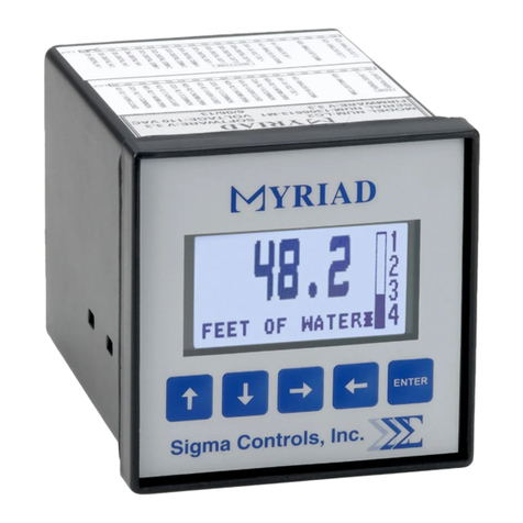
Sigma Controls MYRIAD DPC User manual

1
VISIT OUR WEBSITE SIGMACONTROLS.COM
MYRIAD ‘DPC’ DUPLEX PUMP
CONTROLLER INSTRUCTION MANUAL
VERSION 3.9
MYRIAD DPC MANUAL 071122

2
TABLE OF CONTENTS
INTRODUCTION
3
Ordering Information
Specification
Feature
WIRING DETAIL
7
Dwg # 17-105
Analog Input
Analog Output
Digital Input
Digital Output
PROGRAMMING AND INITIAL SETUP...
9
Input Range Selection
Terminal Block Detail
Initial Setup & Programming
Overview/Key De cription
MAINTENANCE
& TROUBLESHOOTING
..
3
DIAGNOSTICS
4
APPENDIX ‘A’.
7
DPC ADDENDUM
8
AUX PCB ADDENDUM
MODBUS COMMUNICATION
9
30
CONTROLLER SETTINGS
34
WARRANTY
36

3
INTRODUCTION:
The Sigma Myriad DPC (Duplex Pump Controller) i a tate of the art microproce or ba ed,
u er configurable in trument for the monitoring and control of two (2) con tant peed or (2)
variable peed driven pump .
The Myriad DPC perform all of the function found in a full ize control panel.
Di play level in numeric and bargraph form
Di play pump run tatu
Allow full u er election of all y tem variable
Monitor critical alarm (motor overtemperature, etc.)
Monitor non critical alarm ( eal leak, etc.)
Monitor hand off auto election witch po ition
Monitor pump (VFD) ‘run’ feedback
Provide digital and relay output for pump control, level alarm, en or fail, pump fault
and eal leak
Provide 4/20MA output for VFD peed etting with proportional control or P.I.D. etpoint
control.
Retran mit level ignal
Provide time and date ‘ tamped’ alarm information
Continuou en or monitor with ‘ en or fail’ alarm output
Audible and vi ual alarm
Allow imulation of level to exerci e pump or verify operation
Record “MAX” and “MIN” proce value and a graphic trend chart for trouble hooting
Available in ¼ DIN panel mount or Nema 4X enclo ure
Additional Function available with the Optional Auxiliary PCB
Alternation elector hardwired 3 po ition ‘Pump 1 – Auto – Pump 2 ‘
Float Switch Control. 4 Float Control, Low Float Cutout, Single Emergency Float Control
Horn Driver Output
Re et Pu hbutton Input
Seal Leak Input for each pump
ORDERING INFORMATION:
1/4 DIN Ca e Sigma Myriad-DPC-DIN
Wall Mount Nema 4X Sigma Myriad-DPC-N4X

4
SPECIFICATIONS:
ANALOG INPUT (1 ea.) (A econd AI i available when backup en or i enabled)
Analog, 4/20MA, 0-5V, 1-5V, 0-10VDC, i olated with common negative, +-0.1%
accuracy.
DIGITAL INPUTS (7 ea.) (7 additional DI are available with the Aux PCB)
Digital 10-30VDC
ANALOG OUTPUT: (4 ea.)
Analog, with common negative 0-20MA, 4/20MA, 0-5V, 0-10V (voltage output require a
re i tor).
DIGITAL OUTPUTS: (4 ea.) (Horn output available on Aux PCB)
Opto i olated, olid tate, open collector, 100MA 30VDC max.
RELAY OUTPUTS: (4 ea.)
SPDT, Form ‘C’ 5A Relay
DISPLAY:
LCD, 128 X 32 pixel bitmapped graphic di play
LOOP POWER:
24VDC regulated output, 100MA max.
5 USER KEYS:
Up, Down, Left, Right, Enter
ACCURACY:
0.1% of calibrated pan
LOCKOUT:
U er pa word, u er configurable
INPUT IMPEDANCE:
Voltage 100K, current 100 OHMS
POWER:
120VAC (230VAC available)
ENVIRONMENTAL:
Operating, 0-65° C
Storage, -40° -80° C
R.H., 0-90% non-conden ing
ENCLOSURE:
¼ DIN, ABS pla tic 96 X 96 X 124MM or Nema 4X wall mount 12 x 8 x 8 inche

5
FRONT PANEL:
Ga keted Nema 4X
ACCESS: (DIN CASE)
Cha i & board remove from front of ca e.
TERMINAL STRIP:
(40) Removable for ea e of wiring 28 – 16 AWG
CONNECTIONS:
Removable crew terminal block 28 – 16 AWG wire.
CONTROL OUTPUTS:
4 relay output , u er programmable, SPDT Form ‘C’ relay 5 AMP.
4 digital output , Opto i olated, open collector. (Horn output available on Aux PCB)
Digital communication RS485 MODBUS
RTU protocol
OUTPUT ANNUNCIATION:
On board piezo buzzer
CPU Activity Monitor
PROGRAMMING:
Menu ba ed, all parameter and etpoint are u er configurable via menu prompt and
u er key . The preconfigured creen and ‘pull down’ ub menu with Engli h prompt
a ure rapid etup and commi ioning.
1 YEAR WARRANTY
OPTIONS:
Auxiliary Digital I/O PCB with predefined function .
Mi cellaneou Expan ion card , networking
MODBUS
485 RTU
Network allow multiple unit to be connected together for di tributed application or
remote monitoring SCADA application .
NETWORKING:
Significant expan ion i po ible via additional control board and MODBUS
networking. Up to 128 unit may be interconnected, 4000 feet per node.

6
FEATURES:
Microproce or Ba ed
Graphic LCD Di play
5 Function Key
I olated 24VDC Sen or Power
4/20MA, 1-5V, 0-5V, 0-10VDC Programmable input
2 Analog Input
4 Analog Output
7 Digital Input (7 additional DI are available with the Aux PCB)
4 Digital Output (Horn output available on Aux PCB)
4 Form ‘C’ Relay Output
Fully U er Programmable in Engli h
2 Ea. RS485 Port (Programming and SCADA)
CPU Activity Monitor
P.I.D. Control (optional election)
WIRING DETAIL
Input , ee Dwg # 07-105
Output , ee Dwg # 07-105
The range selector switches located on the bottom of the circuit
board are factory set. If a field change of input type is required see
Appendix ‘A’. Do not apply an input signal that is not coordinated with
range switches or the unit may be damaged.
CAUTION
!
All electrical wiring must be in accordance with all local state and national
codes that apply.
Do not exceed the rated current of the D.C. power supply (100MA) or the
form ’C’ relay outputs (5A/ 40VAC resistive).
WARNING
Hazardous voltages are present within the enclosure. Installation or
service should only be carried out by trained personnel.
!
CAUTION

7

8

9
PROGRAMMING & SETUP
The Myriad DPC utilize ‘plain Engli h’ menu driven etup creen which are intuitive and ea ily
under tood.
MAIN DISPLAY
NOTE: To ‘RETURN’ to the main display from any other screen, scroll to ‘EXIT’ and
press ‘ENTER’.
From the default creen (Fig. 1), pu h the ‘ENTER’ button to enter the pa word protected
menu .
Enter the u er elected pa word (factory default i zero) u ing the ↑ ↓ button and pre
‘ENTER’ to acce the fir t programming menu ‘MENU 1’.
NOTE: Programming hould begin at ‘MENU 2’. ‘SCALE’ to et the in trument for the correct
input ignal from ‘MENU 1’. U e the → ← button to highlight the ‘NEXT’ item and pre enter to
acce ‘MENU 2’.
Proce Value
Engineering Unit
Alarm Indicator
Level Indicator
Pump Run Indicator

10
MENU SCALE
U e the → ← button to highlight ‘SCALE’ and pre ‘ENTER’.
U e the ↑ ↓ arrow button to elect the de ired analog input range. NOTE: INPUT TYPE MUST
BE COORDINATED WITH INPUT SELECTOR SWITCH LOCATED ON THE BOTTOM OF
THE CIRCUIT BOARD (See Appendix ‘A’)
The ‘DPC’ doe not include linearization of the input ignal. The di play i linear over the 2
point elected.
NOTE: Highlight ‘NEXT’ and pre ‘ENTER’ to advance to the next creen.
DECIMAL POINT SELECTOR SCREEN
The cur or will be po itioned over the decimal count window. U e the ↑ ↓ arrow button to rai e
or lower the unit number to the left of the decimal point. (The example hown in thi window will
change with your election.)
U e the → ← button to move the cur or over the number behind the decimal point and u e
the ↑ ↓ button to change thi election. Once again, the example will change to confirm your
election.
U e the → ← button to highlight the ‘NEXT’ election and pre ‘ENTER’ to acce the Input
Scale Screen.

11
INPUT SCALING TO ENGINEERING UNITS
NOTE: Thi creen et what the Myriad DPC di play in the main di play for the elected
input. The example hown above will di play 0.0 unit when the input i 4.00 MA. Both the input
and the di play at that input can be changed for different requirement .
A) With the cur or electing ‘4.00’ (or the zero value of the elected input) u e the ↑ ↓ button to
change the input value for the required di played value.
B) U e the → ← button to move the cur or to the ‘di play’ value and the Up/Down button to
change the de ired di play for the previou ly elected input. Once complete, croll to ‘SAVE’,
pre ‘ENTER’ to acce ‘INPUT SCALE 2’ creen.
Follow the tep outlined above to et the value of ‘input’ and ‘di play’ for input Scale 2.
When complete with cale 2, croll the cur or to the ‘SAVE’ po ition and pre ‘ENTER’. Pre
‘DONE’ and pre ‘ENTER’ to move to the “ENGINEERING UNITS” election creen.
This screen available only on some versions.
ENGINEERING UNITS SELECTION:
When ‘Scale Menu’ i complete the ‘INPUT TEXT” menu i the la t menu in the caling proce .

12
Thi creen allow the election of everal engineering unit . With the cur or on the default
value a hown, pre the ↑ ↓ button to elect between:
FEET NTU
INCHES PPM
GPM DEG. F
PSI DEG C
LPM FLOATS
ING HG
MGD
U e the ↑ ↓ button to elect the de ired engineering unit then with the → ← button ,
highlight ‘NEXT’ and pre ‘ENTER’ to acce the “DISPLAY FILTER” creen.
DISPLAY FILTER SCREEN
U e the ↑ ↓ button to change the amount of filtering applied to the input ignal. ‘0’ i no filter
and ‘10’ i high filter.
Too much filtering will dampen process responses.
Scroll to ‘NEXT’ and pre ‘ENTER’ to return to the Menu 2.
ANALOG OUTPUT (AOUT)
U e the → ← key to highlight the ‘AOUT’ item and pre ‘ENTER’ to acce the analog output
ignal etting .
NOTE: There are four analog outputs on the DPC: AOUTPUT 1 and AOUTPUT are
speed vs. level setpoints which are only utilized on variable speed drive applications.
This screen allows the user to program the speed of the drive at a selected level. Both
level and drive speed are selectable.
!

13
SPEED SCALE
The ‘level’ value will be highlighted, u e the ↑ ↓ button to change the level point at which the
peed of the drive ( elected in the next block) i reque ted. In the example above, the drive will
be at 50% peed when the level i 30 inche .
Select a value of drive peed and level a de cribed above and croll to ‘EXIT’ to ave the
value elected and move to analog output 4 creen.
NOTE: When inverting the output direction (as in a pressure application), the speed on
scale one must be lower than the speed on scale . For example, to invert the default
values that are shown here, use the following settings:
Scale 1: Level = 100, Speed = 50%
ANALOG OUTPUT 4 (ANLOUT4) NOTE: Analog output 3 is a nonadjustable
retransmitted signal which ‘mirrors’ the analog input signal.
NOTE: Analog output 4 i retran mitted output which can be caled to any value of the di play.
With the di play value highlighted, u e the ↑ ↓ button to elect a di play value at which a
electable output occur . U e → ← button to move to the output value for the previou ly
elected di play value and adju t a de cribed above.
NOTE: In the example shown 4.00 MA will be output from analog output 4 when the
display value is 0 inches.
From menu 2 u e the → ← button to elect ‘SETUP’ and pre 'ENTER' to acce the etup
menu.

14
SETUP
NOTE: The ‘SETUP’ menu allow acce to the following item :
1) Pump elap ed timer 1
2) Pump elap ed timer 2
3) Trend creen time ba e
4) Pa word
5) Date
6) Alarm Horn on/off
7) Set MODBUS
ID
8) Backup Sen or
9) Alarm Output
10) PID Enable
ELAPSED TIMER 1 &
An elap ed timer i provided to allow the operator to monitor the run time of the two pump .
To re et the #1 timer u e the ↑ ↓ key to change the aved value to zero. Select ‘NEXT’ and
pre 'ENTER' to acce elap ed timer 2. Follow the procedure above to re et thi timer to zero.
U e the → ← key to highlight ‘NEXT’ and pre the 'ENTER' key to move to the trend creen
peed creen.
TREND SPEED SCREEN
NOTE: The trend creen i provided a a diagno tic tool. Thi trend graphic will di play the
proce value over the time duration elected. The duration of the trend i electable between 2
minute , 2 hour , 12 hour and full peed. The trend i non-retentive and will overwrite previou
data.
U e the ↑ ↓ key to elect the de ired time ba e and croll to ‘NEXT’ and pre ‘ENTER’ to
move to the ‘Change Pa word’ creen.

15
CHANGE PASSWORD SCREEN
Once the password has been changed make sure a record of the new
password is retained. Access to the programming menus requires a
correct password.
U e the ↑ ↓ key to enter a number up to 9999, elect ‘NEXT’ and pre ‘ENTER’ to enter the
‘change clock’ menu.
CHANGE CLOCK, MONTH, DATE AND DAY SCREENS
A de cribed previou ly, u e the ↑ ↓ key to et the creen to the current time. Scroll to ‘NEXT’
and pre ‘ENTER’ to move to the change month creen.
The ‘CHANGE MONTH’ creen, ‘CHANGE DATE’ creen and ‘CHANGE DAY’ creen are all
adju ted a above. After changing the ‘DAY’ creen, croll to ‘NEXT’ and pre ‘ENTER’ to
elect the ‘Alarm Horn’ creen.
NOTE: DAYLIGHT SAVINGS CHANGES ARE AUTOMATIC.
ALARM HORN SCREEN
NOTE: Selecting the alarm horn to ‘OFF’ will di able the internal piezo alarm from ounding
when an alarm condition occur .
!

16
Allow the MODBUS
comm port to be et to match network requirement . Exit to ave, then
cycle Power to adopt new node.
High and low level alarm are available on Relay 3. If de ired thi election will provide high
level alarm on RLY #3 and low level alarm on digital output #4. (24VDC relay required.)
When the de ired election are made, croll to ‘NEXT’ and pre ‘ENTER’ to return default
creen.
Select 'EITHER SEAL LEAK' for the tandard monitoring of the pump ’ eal leak contact
clo ure . [Default]
Select 'BACKUP SENSOR' if u ing a backup level tran mitter in thi mode. A primary en or
failure will change operation to a econdary en or. (Do not u e if u ing a ingle level en or.)
Set Dip witch 7 to up and 8 to down.
Select ‘RESET PUSHBUTTON' To u e AI3 for an external alarm re et pu hbutton.
Select 'PID' (proportional, integral, derivative), control provide a etpoint for the controller to
maintain. (U e for boo ter and imilar application .)

17
Select 'REVERSE' to drive the output down when the proce value exceed the etpoint, a in
pre ure boo ting application .
Select 'FORWARD' to drive the output up when the proce value exceed the etpoint.
Select 'DUPLEX' for two pump operation
Select 'SIMPLEX' when pump 2 i not in talled.
The Auxiliary PCB i a factory in talled option. When in u e, thi creen mu t be enabled,
otherwi e all of it function will be di abled.
The Auxiliary PCB ha input for float witche . Thi mu t be enabled to u e tho e function .
The Auxiliary PCB # 3 terminal can be u ed a a normally clo ed hutdown or a low float cutoff
to top the pump on a low water condition. Di able thi feature when not in u e to avoid the
need for a jumper.

18
When float control i enabled it erve a a backup control to the analog level en ing. Thi
etting control at what point the float a ume control.
Select LEAD FLOAT to initiate backup control when the float above the low float i tipped. U ed
when the top 3 float are hanging above the normal pumping range.
Select LAG FLOAT to initiate backup control when the 2
nd
float above the low float i tipped.
U ed when the top 2 float are hanging above the normal pumping range.
Select HIGH FLOAT to initiate backup control when the high float i tipped.
Select SINGLE FLOAT to initiate emergency operation of both pump . No other float need to
be in talled for thi mode.
Select NONE-FLOATS ONLY u e the controller with only float . The level en or will be
di abled.
MENU 1
From Menu 1 elect ‘Setting ’ and pre ‘ENTER’ to acce the ‘LEAD PUMP ON’ etpoint.
LEAD PUMP ON
NOTE: Thi parameter determine at what level the ‘lead’ pump turn on. U ing the ↑ ↓ button
elect a level point to turn on the lead pump. Scroll to ‘NEXT’ and pre ‘ENTER’ to acce the:
LEAD PUMP OFF SCREEN

19
Following the procedure above, elect a level value at which the lead pump turn off. U e
‘NEXT’ with the 'ENTER' button to acce the:
LAG PUMP ON SCREEN
Select a value which turn on the lag pump. U e ‘NEXT’ and ‘ENTER’ to acce the:
LAG PUMP OFF SCREEN
Again, elect a level value which turn off the lag pump. Select ‘NEXT’ and pre ‘ENTER’ to
advance to the:
PUMP ON DELAY SCREEN
Thi creen allow an operator elected delay before a pump i operated after it ‘ON’ etpoint
ha been reached. Sometime thi delay i required to overcome proce di turbance uch a
pre ure or wave action.
Change the ‘ON’ delay a required and elect ‘NEXT’ and pre ‘ENTER’ to advance to the:
PUMP OFF DELAY SCREEN

20
Change pump off delay a de cribed above and elect ‘NEXT’ and pre ‘ENTER’ to advance to
the:
LEVEL ALARM SCREENS
The next creen are a follow :
Low Level Alarm Set Point
Low Level Alarm Re et Point
High Level Alarm Set Point
High Level Alarm Re et Point
Alarm Timer (Thi function control the timing for alarm to be detected)
Adju t and advance through the alarm etting a de cribed previou ly. The ‘alarm timer’
provide an adju table time delay for alarm notification after the alarm etpoint ha been
reached in order to prevent nui ance alarm .
After the ‘alarm timer’ ha been et, exit etting and return to Menu 1, elect ‘ALT’, pre
‘ENTER’ to acce the alternation menu.
‘ALTERNATION’
NOTE: Three option are available for alternating the pump lead po ition:
A) ‘ALT OFF’ no alternation of lead/lag pump.
B) ‘WHEN PUMPS STOP’ pump alternate when a pump ha completed a pump cycle.
C) ‘DAILY’ allow for alternation of the pump in y tem which run continuou ly.
Selecting ‘DAILY’ bring up a new election which i the time of day at which the pump
will alternate their po ition in the equence even if they are operating.
U e the ↑ ↓ key to elect a time of day to alternate. Select ‘NEXT’ and pre ‘ENTER’ to return
to Menu 1.
From Menu 1 elect ‘ALARMS’ and pre ‘ENTER’ to view the current alarm tatu .
ALARMS
Table of contents
Other Sigma Controls Controllers manuals
Popular Controllers manuals by other brands

Magicfx
Magicfx FX-COMM4NDER MFX3203 User and installation manual
Oriental motor
Oriental motor NX Series operating manual

Oriental motor
Oriental motor LIMO EZS Series user manual
Secu-tech
Secu-tech LC200 Operating instruction
MICROMATIC
MICROMATIC Rotac 26R OVERHAUL INSTRUCTIONS
Krom Schroder
Krom Schroder E8.5064 V1 operating instructions
