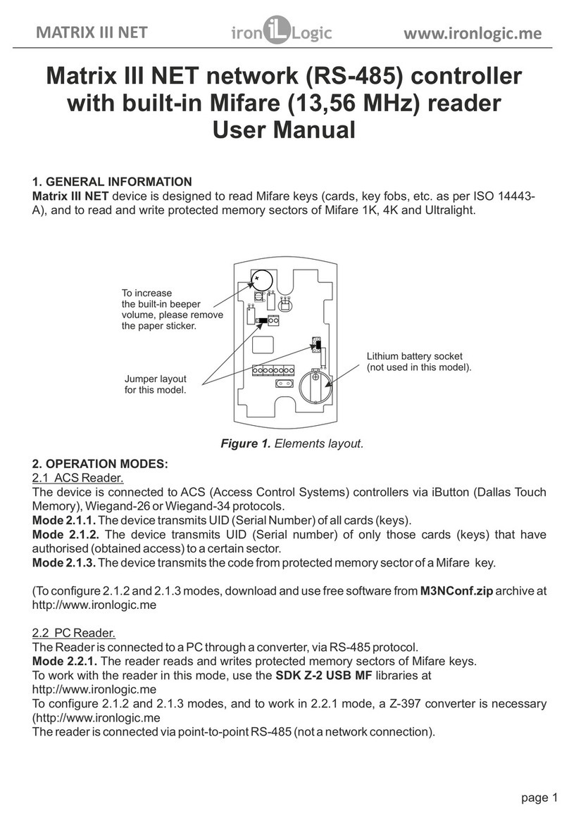
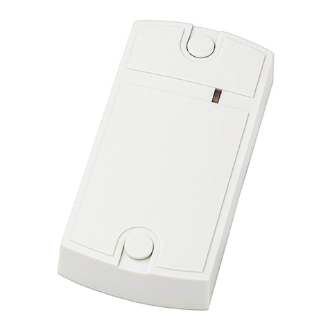
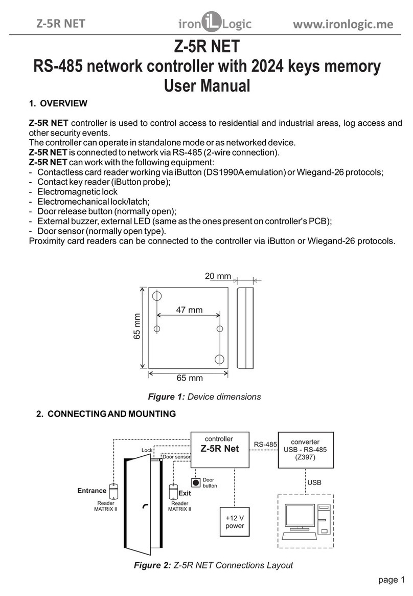
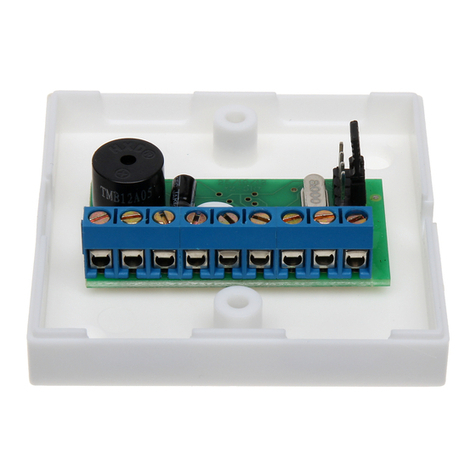
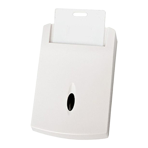
Iron logic Z-5R WEB mini User manual

1
1. GENERAL INFORMATION
Controller Z-5R WEB mini is intended for use in access control systems
(ACS) and provides control of a single access (pass) point.
Controller operation management (changing the operating modes and key database) is
possible in the standalone mode using master keys or via an integrated web interface, as well as
using an external controlling software in the so-called network mode. Additionally, in network
mode, it is possible for the controlling software to receive the controller event log.
In both modes, the controller makes the decision to allow access independently based on the
internal key database and the current mode of operation regardless of the existence of a
connection with the controlling software. To operate in the network mode or with the integrated
web interface, the controller must be connected to the Wi-Fi network.
In the configuration mode, the controller itself becomes an access point providing the means of
communication with it to connect it to an existing Wi-Fi network and configure other parameters.
Access through the pass point is carried out based on checking the status of the presented
identifiers (proximity cards, Touch Memory keys or pin codes), which will be hereinafter referred to
as keys.
By their functional purpose, the controller distinguishes between keys intended for passes and
keys intended for programming the controller.
Pass keys can be common and blocking. Blocking keys have a higher status.
In normal mode, the controller "allows" to pass using both common and blocking keys.
In the "Lock" mode, the passage through the blocking keys is allowed but the passage through
the common keys is closed (for example, when issuing common keys to employees and blocking
keys to security officers,
it is possible to provide passage to all categories of employees during working hours in normal
mode, but only security officers will be allowed to pass at night in the lock mode).
The keys for programming the controller are called master keys. They are designed only for
programming the controller without a computer and not intended for passage. Master keys
allow you to: add/remove common, blocking and master keys, set the time of sending the opening
signal to the locking device (access permissions), enable/disable the "Accept" pass mode.
In the "Accept" mode, any key is perceived as resolved and written into the controller memory
as a common key for passing. The mode is used to generate a key database when installing ACS
at the site when the keys for passage have already been issued. Then, being for some time in the
"Accept" mode, the controller "collects" information about the presented keys and after enabling
the normal mode, the passage will be carried out only through the keys written into its memory.
To obtain key codes, the controller supports the connection of 2 readers (for the entrance and
the exit) via the Wiegand (26, 34, 42, 50) or iButton (Dallas Touch Memory) protocols. After
checking the access rights, the controller issues a control signal (on/off the power transistor) to the
locking device (electromechanical lock, electromagnetic lock or latch, turnstile). The type of shut-
off device and the protocol for connecting the readers are selected in the controller configuration
mode.
Z-5R WEB mini www.ironlogic.me
Controller Z-5R WEB mini
User Manual

2
The controller allows 2048 events to be stored in a cyclic buffer (receiving the code, triggering
the door sensor, issuing a control signal, etc.).
To increase the functionality of the operation, the controller allows to:
• connect a door sensor - to record the event "the passage occurred" and reduce the time
the sound alarm is active and inform about the unlocked door (reduce the time of sending
the "opening signal" to the locking device);
• connect the "exit button" to open the door without checking access rights;
• receive a signal by the controller from an external source for emergency door unlocking.
Wi-Fi communication module
Standards: IEEE 802.11 b/g
Frequency range: 2.4-2.4835 GHz
Transfer rate 11g: up to 54 Mbit/s
11b: up to 11 Mbit/s
Wireless signal strength: <20dBm (<100mW)
Operation mode: Access point, client
Wireless network security: WPA/WPA2, WPA-
PSK/WPA2-PSK
USB Interface
Connector: USB Type micro A
Version: USB 2.0
Mode: Device, Full/Low Speed
Other parameters
Light and sound indication of operation
modes:
Yes
DC power supply voltage, V: 12 (9–24 allowed)
Maximum current consumption at 12 V, mA: 100
Incorrect power-on protection: Yes
Dimensions, mm: 64х64х19
Weight, kg, not more than: 150
Controller
Key memory, pcs. 2024
Event memory, pcs. 2048
Number of connected readers
(contactors), not more than:
2
Connection protocols:
contactor readers
iButton, Wiegand
iButton
Reader indication control: yes
Output for lock connection: MOS transistor
Power output current, А:5
Jumper to select the lock type: electromagnetic
electromechanical
Lock opening duration setting, sec: 0.1 to 6,500
(factory value - 3)
2. TECHNICAL SPECIFICATIONS
Z-5R WEB mini www.ironlogic.me

3
3. CONNECTING EXTERNAL DEVICES
The figure shows the overall dimensions and terminal layout on the board of the device:
THE PURPOSE OF THE TERMINALS IS SHOWN IN THE TABLE
Fig.1 Overall dimensions and terminal layout.
ZUMM For connecting an external buzzer. It is necessary to use a buzzer with a built-in
generator for a voltage of 12 volts and a consumed current of not more than 200
mA. The positive pin should be connected to the terminal + 12V, and the negative
pin should be connected to this terminal.
TM External reader or contactor, in Wiegand mode: DATA0 signal.
GND Signal ground. To connect the common wires of the external reader,
contactor, door position sensor and door opening button.
EXIT Door opening button. Internal reader or contactor
can be connected simultaneously. In Wiegand mode: DATA1 signal.
LED Control of the green LED of the external reader.
LOCK Terminal for connecting the negative wire of the lock winding.
+12V +12 Volt.
Connection of the positive pin of the power supply and the positive lock winding wire.
GND Power ground. Connection of the negative pin of the power supply.
DOOR Connection of the door position sensor. Twisted pair is recommended. When the
door is opened, the triggered sensor allows turning off the sound on the controller
prematurely, as well as saving energy by turning off the electromechanical lock
immediately after opening the door or turning on the electromagnetic lock only when
the door is already closed.
CFG
CLR
CR2032
iron iL Logic
DOOR
+12V
LOCK
EXIT
GND
ZUMM
ADD
GND
TM
LED
Z-5R WEB mini
58
58
64
19
64
Z-5R WEB mini www.ironlogic.me

4
Fig. 3 Connection diagram for external devices.
Entrance ТМ
Reader entrance and exit
IN. READ
Optional connection:
- External buzzer
- External LED (SDI)
- Door opening button
- Door position sensor
Fig.4 Connection of external readers via iButton protocol.
GND TM
EXIT
LED
LOCK
+12V
GND
DOOR
ZUMM
DATA 0
+12V
GND
GND TM
EXIT
LED
LOCK
+12V
GND
DOOR
ZUMM
DATA 0
+12V
GND
Exit
Entrance
Exit
button
Reader 2
Reader 1
Z-5R WEB mini
Z-5R WEB mini
Power
supply
Reader
MATRIX-II
Reader
MATRIX-II
Entrance Exit
Sensor
Lock
Door
opening
button
Controller
Z-5R WEB mini
12V
CFG
CLR
CR2032
iron iL Logic
DOOR
+12V
LOCK
EXIT
GND
ZUMM
ADD
GND
TM
LED
Z-5R WEB mini
Fig. 2 Connection diagram for Z-5R WEB mini.
Entrance ТМ
External buzzer
Lock
Button
External buzzer
Ground (-)
Door opening
button
External SDI (+)
Lock
+ 12 V
Ground (-)
Door sensor
Door sensor
PS 12V
Z-5R WEB mini www.ironlogic.me

5
4. DEVICE NETWORK CONNECTION METHODS Z-5R WEB mini
When using the device in network mode, you'll need to adjust your Wi-Fi network connection
settings. It should be noted that by its functions, the Z-5R WEB mini device consists of two units:
the ACS controller itself and the module for communication with the local computer network via
the Wi-Fi protocol.
The communication module provides connection of the device to the local network available at
the site via the Wi-Fi interface and establishes the connection with the computer with the ACS
control software is installed, which implements access control functions (map list downloading,
access right setting, event reading from the buffer, etc.).
According to the method of establishing a connection with the control software, three modes are
available:
-WEB communication mode. In this mode, the communication module connects to the
controlling web server on the Internet and the device is controlled via the website
(for example, "cloud" ACS - www.guardsaas.com);
Fig.5 Connection of external readers via Wiegand protocol.
+12V
GND TM
EXIT
LED
LOCK
GND
DOOR
ZUMM
+12V
GND
DATA 1
LED-G
LED-R
BEEP
DATA 0
TM
EXIT
LED
LOCK
GND
DOOR
ZUMM
+12V
GND
Entrance
Exit
button
Reader 1
Reader 2
+12V
GND
DATA 1
LED-G
LED-R
BEEP
DATA 0
EXIT
TM
Reader
DATA 1
DATA 0
Z-5R WiFi
EXIT
TM
Reader
DATA 1
DATA 0
Z-5R WEB mini
Z-5R WEB mini
Fig.6 Connection of contactors.
Entrance
and exit
contactors
CFG
CLR
CR2032
iron iL Logic
DOOR
+12V
LOCK
EXIT
GND
ZUMM
ADD
GND
TM
LED
Z-5R WEB mini
Z-5R WiFi
Z-5R WEB mini www.ironlogic.me

6
- Server communication mode. In this mode, the communication module listens for a connection
using the TCP/IP protocol from the computer with the control software installed (for example,
GuardLight, GuardCommander, Avangard);
- Client communication mode. In this mode, the communication module tries to establish a
connection on its own via the TCP/IP protocol with the control software. To configure this mode,
you need to specify the IP address and TCP port on the remote computer (for example, in
GuardLight or Avangard software);
Web server
DB
Wi-Fi
Internet
Wi-Fi
Z-5R WEB mini www.ironlogic.me

7
5. WEB INTERFACE
The web interface is used to configure communication parameters and connected equipment.
To perform the first configuration, you need a device that can connect to the network via Wi-Fi
(tablet, laptop or smartphone) and has an integrated Internet browser (Internet Explorer, Firefox,
Opera, Chrome, etc.).
To access the web interface of the device settings, you need to perform the following actions:
1. Set the jumper to CFG position (see P 6 "Turning on the device and getting started");
2. Turn on the power supply;
3. Connect your device to Wi-Fi:
- Wait for the appearance of a Wi-Fi network named Z-5R WiFi_XXXXXX;
- Connect to this network (connection password - AUTH_KEY);
The factory value AUTH_KEY of the eight-character is shown on the label located on the back
of the device case or at the end of this manual (case sensitive!).
4. Using a browser, open the page at http://192.168.10.1 (login: z5rwebmini, password
AUTH_KEY);
5. Scrolling through the menu pages, configure the settings (remember to press Save on each
page).
After the configuration is complete, you should remove the jumper from the CFG position, reboot
the controller and wait for the Z-5R WEB mini to connect to the local network. Now the web
interface will be available at the IP address that was assigned to the device during configuration
(will be described below in P 5.3) or received from the router (DHCP server) when registering in
the local network.
5.1 Language selection
At the first activation, English is set in the web interface. To select the Russian language, click on
the "Russian" in the upper right corner of the interface:
5.2 Status tab
The Status tab displays the current status of the device:
Z -5 R WEB mini
SN:46-000001
Status
Mode:
Connection:
Run time:
Controller software version
Communication module software version
CFG jumper
WEB
0 days 00:01:01
2.22
1.09
On
Z-5R WEB mini www.ironlogic.me

8
Here:
Network (SSID): A name of the Wi-Fi network to which the device will be connected.
Password: An encryption key (password) used on the above Wi-Fi network.
Search for networks: Activation of the search for currently available Wi-Fi networks. After
searching for available Wi-Fi networks will be finished, a list of found networks will appear with a
signal strength displayed:
To select a network, highlight the desired network and then press OK. Then the name of the
Wi-Fi network will automatically appear in the settings. If the network does not broadcast its
name, you must enter the network name manually in the Network (SSID) field. When using
encryption, you must enter the encryption key.
Mode: A device operating mode (WEB, Server, Client, Standalone).
Connection: In the Client and Server modes, it displays the IP address of the computer to
which the connection is established.
Run time: the duration of the device's operation from the moment of turning the power on.
Controller software version: Displays the current firmware version of the controller.
Communication module software version: Displays the current firmware version of the
communication module.
CFG jumper: displays the status of a jumper: On - installed, Off - removed.
5.3 Connection Settings tab
On the Connection Settings tab, the method and parameters for connecting the communication
module to the local network can be set. Setting the parameters is similar to setting up an
Internet router.
Connection Settings
Network (SSID) mySSID
WiFiPassword
192.168.1.129
255.255.255.0
192.168.1.1
Password
8.8.8.8
Use DHCP
Static IP
Subnet mask
Gateway
DNS server
Search for networks
Save
Network test
Wi-Fi
IP
Connection Settings
Available Wi-Fi networks
NET.111
ironlogic
default
-90 dBm
-76 dBm
-88 dBm
OK
Z-5R WEB mini www.ironlogic.me

9
Network test: Verification of connectivity with the current SSID and password values. However,
with the correct password, the router may refuse in connection because it can be configured to
check the MAC address of the device.
Use DHCP: Instructs to access a DHCP server to automatically
obtain the IP address and other network parameters necessary to operate on this local network.
If there is no DHCP server, you must correctly configure the following network settings:
Static IP: A unique IP address that provides the device's address on the local network.
Subnet mask: A subnet mask used on this local network.
Gateway: An IP address of the gateway to communicate with other networks (including the
Internet).
DNS server: An IP address of the DNS server.
For correct operation, all the specified parameters must be set. If you do not know some of the
parameters, please contact your system administrator.
When the configuration is complete, you must press Save.
5.4 Operating Mode tab
If Z-5R WEB mini is intended to operate in the network mode, i.e. controlled by external
software, then after configuring the connection to the local network, it is necessary to configure
the mode of establishing communication between the controlling software and the
communication module. On the Operating Mode tab, the desired method of connection to the
software when operating in the network mode can be selected:
Here:
Authentication key: An authentication key is required to connect to the cloud Internet server in
the WEB mode when operating through the server, as well as to access the web interface of the
Z-5R WEB mini device.
Initially, the factory value indicated on the label on the device casing is displayed here (see
AUTH_KEY). At this configuration stage, it can be changed, if necessary (numbers and Latin
letters are allowed).
Operating mode: Selection of the network mode of operation - WEB, Server, Client -
or selection of the Standalone mode of operation.
Operating mode
General settings
Authentication key DEADBEEF
Operating mode WEB
Z-5R WEB mini www.ironlogic.me

10
5.4.1 Web
The WEB mode provides a connection with the "cloud" service. To configure the WEB
operating mode, it is necessary to check with the service provider and set the following
parameters:
Server address: A name or IP address of the WEB server of the "cloud" service to which the
controller will connect.
Use HTTP proxy: Specifying the need to contact a special server on the network
to access the Internet.
Proxy server address: A network address of the proxy server on the local network.
Proxy server port: A port for connecting to the proxy server.
Password: A password to access the data on the WEB server.
Connection interval: An interval of connection to the WEB server in seconds.
Number of events: A number of events in the controllers when data is prematurely sent to the
WEB server before the transmission interval expires.
When all the parameters are configured, you must press Save.
5.4.2 Server
In this mode, the communication module awaits for the control software to connect to its opened
local port. If the server operating mode is selected, the following should be set:
Here:
Local port: A TCP port to which the control software will be trying to connect.
Allowed IP: An IP address of the computer from which the control software is allowed
to connect to the controller (255.255.255.255 to allow all IP addresses).
When all the parameters are configured, you must press Save.
5.4.3 Client
If the Client operation mode is selected, the communication module will regularly try to establish
a connection with the control software.
The following parameters should be set:
hw.guardsaas.com
192.168.10.1
3128
10
1
Server address:
ab974088d09d4dc3
Use HTTP proxy:
Proxy server address:
Proxy server port:
Password:
Connection interval:
Number of events:
WEB
Server
1000
Local port:
255.255.255.255
Allowed IP:
Client
192.168.1.10
25000
Server address:
Server port:
Z-5R WEB mini www.ironlogic.me

11
Accept mode: Enables the Accept mode, in which all unknown keys are written to memory as
new common keys.
Access mode: The possible values are Normal (normal mode of passage),
Lock (passing via blocking cards), Free Passage (the pass is open), Waiting (set only via the
web interface for the case when the controlled access point is set to the Lock mode, so the first
scanned card (common or blocking, but not a master card!) will switch the access mode to the
Free Passage position).
Key adding mode: Switches the device into the mode for adding common and
blocking keys (see Paragraph 7.1 for details).
Master key adding mode: Switches the device into the mode for adding master
keys (see Paragraph 7.2 for details).
Key deletion mode: deletes a common or blocking key scanned by the reader from the
database (see Paragraph 7.3 for details). Master keys are not deleted in this mode.
When enabling the "Key adding", "Master key adding" and "Key deletion" modes, a countdown
timer will appear on the corresponding button showing the time remaining until the mode is
automatically turned off.
Here:
Server address: An IP address of the computer to which the device should establish
a connection to communicate with the controlling software.
Server port: An IP port to which the connection must be made.
When all the parameters are configured, you must press Save.
5.4.4 Standalone
The initial configuration of the ACS, which, for example, on the Z-5R controller is performed
using jumpers, on this device should be done using the Standalone mode. This mode is
designed to work with the list of controller keys without using the master key via the web
interface. To ensure the configuration of the key database, you can
use an external reader connected to the device Z-5R WEB mini via
the iButton protocol (configuring the key database using a reader connected via the Wiegand
protocol is not supported!).
In the case of controlling the device operation through the web interface, you should select the
Standalone operation mode. Then the control interface will be the following:
Standalone
Accept mode:
Access mode:
Key adding mode:
Master key adding mode:
Key deletion mode:
Normal
On
On
On
Z-5R WEB mini www.ironlogic.me

12
Lock type: Selects the type of lock: Electric Latch, Electromagnetic, Electromechanical. If the
lock type is configured by the controlling software, then changing the lock type cannot be done
until it's reset to factory settings using the web interface or jumper (position 2, see page 50) and
the "Lock Type" field displays the name of the configured pass point.
Internal sound: Enables/Disables the integrated audio source.
Wi-Fi indication: Enables/Disables the Wi-Fi network connection status by flashing the blue
light. Indication description: constant flashing - searching and connecting to a Wi-Fi network;
flashing 3 times in succession - configuration mode (CFG jumper is installed); flashing 2 times in
succession - a connection to the controlling software (server) is established; single flashes -
waiting for a connection to the controlling software (server).
Opening intervals: the duration of the pulse sent to the shut-off device for unlocking the
passage. Depending on the type of lock, this can be both voltage removal and supply.
Opening control time: waiting time for the door to open when the passage is allowed. Opening
the door after this time is qualified as a break-in. If a set value is lower than "Opening time",
"Opening Time" will be used for this function.
Closing control time: time to control the opened state of the door. If the door is not closed
within the set time, the "Door left open" event will be generated. A value of "0" disables control.
Synchronise time over NTP: Allows accessing a time server (NTP) to synchronize the device
clock.
NTP server: The address of the NTP server used in time synchronisation.
Time zone: The time zone used when synchronising the time.
Open the door: Buttons that open the entrance or exit passage.
When all the parameters are configured, you must press Save.
5.6 Advanced Settings tab
The Advanced Settings tab allows you to update the device software, download and upload
configuration files, update the device firmware, restore factory settings and reboot
the Matrix-II Wi-Fi:
5.5 Controller Settings tab
The Controller Settings tab allows you to set the parameters of the device Z-5R WEB mini
controller operation:
Controller Settings
Electromagnetic
UTC+3
10 x 0.1s.
x 0.1s.
x 0.1s.
30
0
pool.ntp.org
Save
Entrance Exit
Lock type:
Internal sound:
Wi-Fi indication:
Opening intervals:
Opening control time:
Closing control time:
Synchronise time over NTP:
NTP server:
Time zone:
Open the door:
Z-5R WEB mini www.ironlogic.me

13
Restore factory settings: restores the default settings.
Configuration file save: saves the controller settings to a file used for configuration on the
device.
Configuration file upload: uploads the saved settings from a file used for configuration on the
device.
Controller reboot: Restarts the device for the settings changes to take effect.
Firmware update: allows you to update the device software of both the controller and the
communication module.
5.7 Shutting down the web interface
To turn off the web interface, it is necessary to remove the jumper from the CFG position if it was
installed (see P 6 "Turning on the device and getting started"), select the Advanced Settings tab
and press the "Restart" button in the menu
"Controller Reboot".
6. TURNING ON THE DEVICE FOR THE FIRST TIME AND GETTING STARTED
Connect external devices to the controller in accordance with Section 3.
Default (factory) settings of the Z-5R WEB mini communication module:
Network name: "mySSID"; password: "WiFiPassword"; protocol - Wi-Fi, mode - DHCP;
connection establishing mode - WEB, server - hw.guardsaas.com.
Attention! Changing the communication module settings is possible only via web
interface.
If you intend to use the device in network mode with network parameters different from the
factory settings, then change the factory settings in accordance with paragraph 5 of this manual.
Using the web interface, it is also possible to configure settings for operation in the Standalone
mode. To operate the device in the standalone mode, it is necessary to select the "Operating
Mode" tab via the web interface, enable the "Standalone" mode of operation and create at least
one master key (see paragraph 7).
Next, keeping the standalone mode of operation, exit the web interface and create keys for the
passage.
After changing the settings, turn off the power. Remove the jumper from the CFG position and
set it according to the type of lock used. Turn on the power supply. The device is ready to work
in the mode selected in the settings.
If the device is intended to be used only in the standalone mode, the jumper located on the
device card is used to configure it:
Advanced Settings
Restore factory settings:
Configuration file save:
Configuration file upload:
Controller reboot:
Firmware update:
Reset
Save
Upload
Reboot
Update
Z-5R WEB mini www.ironlogic.me

14
This jumper can be in one of five positions:
Position No. 1 - selection of an electromechanical lock (in the "closed" position, the voltage is
removed from the lock) (see Note 1).
Position No.2 CLR (clear) - to erase the memory (database) of the controller and
restore the factory settings of the communication module. To do this, turn the power off, set the
jumper and turn the power on. Upon deletion, a series of short audio signals will be produced.
All keys (cards) and the programmed time of opening the door are erased (the factory value of 3
seconds is set).
Position No. 3 ADD (addition) - to add common and blocking cards to the controller memory
without using a master card. To do this, turn the power off, set the jumper and turn the power
on. After the beep, the controller will be switched into the mode for adding common cards: You
can add common (short-time scan) and blocking (long-time scan) cards without using a master
card. 16 seconds after the last card is scanned, the controller exits the mode of adding common
and blocking cards (a series of short beeps will sound).
Position No. 4 - selection of an electromagnetic lock (in the "closed" position, a voltage is
applied to the lock). If the jumper is not installed at all, it is considered to be "set" to position 4,
i.e. the connection of the electromagnetic lock is chosen (see Notes 1 and 2).
Position No. 5 CFG When power is supplied, the device starts in the communication
parameter and connected equipment configuration mode (see Paragraph 5). In this mode, the
lock is de-energised.
Note 1. If the lock type was configured using the web interface or a controlling software (for
example, GuardLigth), then setting the jumper to position 1 or 4 does not affect the selection of
the lock type until the factory settings are restored using the web interface or jumper (position 2).
Note 2. With a large number of passes (for example, every 10 seconds), the output circuit
may fail due to overheating. To protect the circuit, such passage points must be equipped with
bypass diodes parallel to the lock winding. After that, the response (opening) time of the
electromagnetic lock may increase by 1-3 seconds. If such an increase in time is unacceptable, it
is recommended to install a variable resistor in series with a diode for a voltage of up to 14 V and
dissipated energy from 0.7 J (V8ZA2P is recommended) (see Fig. 3).
1
2
3
4
5
CLR
ADD
CFG
Fig.7 Jumper.
Z-5R WEB mini www.ironlogic.me

15
Light and sound indication of the operation of the Z-5R WEB mini
- Adding common keys - 1 long scan.
- Adding master keys - 1 short and 1 long scan.
- Deleting common keys - 2 short and 1 long scan.
- Erasing all keys (from the controller memory) - 3 short and 1 long scan.
- Setting the door opening time - 4 short scans.
- Switching to the "Accept" mode - 5 short scans.
- Disabling the "Accept" mode - 1 short scan.
7.1 Adding common keys
Place and hold the master key (long scan). At the moment of touching, the controller of the
device (hereinafter referred to as the controller) will produce a short signal confirming the
authorisation of the master key, and after 6 seconds it will produce a second signal indicating the
controller switching to the mode for adding common keys. After that, the master key should be
put away. To add new keys, place them on the reader one after another with a pause between
touches of less than 16 seconds. Each contact with a new key will make the controller emit a
short confirming signal. If the new key is placed and held in the field of the reader for more than
3 seconds, it will be recorded as a blocking card. If the placed key is already in memory, the
controller will emit two short signals. The mode is switched off either automatically 16 seconds
after the last touch or when you place the master key on the reader. The controller informs you
about the end of the mode with a series of 4 short signals.
7.2 Adding master keys
Briefly tap the reader with the master key (short tap). At the moment of touching, the controller
will give a short signal confirming the authorisation of the master key, so after no more than 6
seconds place and hold the master key on the reader (long touch).
A red LED is on indicating the working state and the supply of power.
When bringing the card close to the reader, the following responses are possible:
- card is in the database of the Z-5R WEB mini controller the green LED flashes,
the buzzer signal sounds, the lock is open for the set time of opening the lock (or until the door
position sensor is triggered);
- card is not in the database of the Z-5R WEB mini controller - the LED flashes (green and
red), two short sound signals are heard.
When the "Wi-Fi indication" option is enabled (see Paragraph 5.5.), the above indication will be
interrupted by blue LED flashes displaying the status of the connection to the Wi-Fi network.
7. SETTING UP THE DEVICE USING A MASTER KEY
To control the device (switch to the desired programming mode: Creating/Deleting common and/
or blocking cards, enabling the "Accept" mode, etc.) short (less than 1 sec) and long (about 6
sec) scans (touches) of the master card (master key) by an external reader connected via the
iButton protocol are used.
Attention: to control, or as is often said - "programming" the device, readers connected via the
Wiegand, protocol are not supported due to the nature of the protocol.
There is a time limit to work in each programming mode (about 16 sec after the last card was
scanned by the reader). After that, the device exits the programming mode informing you with a
series of 4 short signals.
The following programming modes are available:
Z-5R WEB mini www.ironlogic.me

16
At the moment of the second touch, the controller will give two short signals indicating a second
touch with the master key in programming mode, and after 6 seconds the controller will emit one
signal indicating the switching of the controller to the master key adding mode. After that, the
master key should be put away. To add new master keys, place them on the reader one after
another with a pause between touches of no more than 16 seconds. Each contact with a new
key will make the controller emit a short confirming signal. If the key already exists in memory as
a master key, there will be no signals. Adding master key mode will be automatically turned off
16 seconds after the last scan. The controller informs you about the end of the mode with a
series of 4 short signals.
7.3 Deleting common keys
Briefly touch the reader with a master key twice (short taps). At the moment of the first touch,
the controller will give one short signal confirming the authorisation of the master key. At the
moment of the second touching, the controller will give two short signals indicating a second
touch with the master key in the programming mode, so after no more than 6 seconds place and
hold the master key on the reader (long touch). At the moment of the third touch, the controller
will give three short signals and one signal after 6 seconds indicating switching to the common
key deletion mode. After that, the master key should be put away. To delete common and
blocking keys, place them on the reader one after another with no more than a 16-second
interval between touches.
Each contact with a key to be erased will make the controller emit a short confirming signal. If the
key is not in memory, the controller will emit two short signals. The mode is switched off either
automatically 16 seconds after the last touch or when you place the master key on the reader.
The controller informs you about the end of the mode with a series of short signals.
7.4 Deleting all keys (from the controller memory)
Briefly touch the reader with a master three times (short taps). At the moment of the first touch,
the controller will give one short signal confirming the authorisation of the master key. At the
moment of the second touch, the reader will give two short signals indicating the second touch
with the master key in the programming mode. At the moment of the third touch, the controller
will give three short signals indicating the third touch with the master key, so after no more than 6
seconds place and hold the master key on the reader (long touch). At the moment of the fourth
touch, the controller will give four short signals and a series of short ones after 6 seconds
indicating the erasure of the controller memory and exiting the programming mode. After that,
the master key should be put away.
*-When erasing the entire database using a master key, the programmed lock opening time is
not erased.
7.5 Setting the lock opening time
Four times briefly place the master key on the reader. At the moment of each touch, the
controller will give signals confirming the authorisation of the master key, and their number will
correspond to the number of touches. At the moment of the fourth touch, the controller will
respectively give four signals and enter the opening time programming mode. Within 6 seconds
from the last touch, you must press and hold the door opening button for the time it takes to
open. After releasing the button, the controller will generate a signal and record the time in
memory. For fine-tuning, we recommend using the web interface.
Z-5R WEB mini www.ironlogic.me

17
7.6 Enabling/Disabling the "Accept" mode
The "Accept" mode is used to write all the keys touching it to the device's memory. In this mode,
the pass is unlocked by the key touching the reader, and at the same time, it is written into the
controller memory, if it is not there. The mode is used to restore the controller database without
collecting user keys. A master key is required to enable the mode. Five times briefly touch the
reader with the master key. At the moment of each touch, the reader will give signals confirming
the authorisation of the master key, and their number will correspond to the number of touches.
At the moment of the fifth touch, the reader will give five signals respectively and another long
signal after a few seconds confirming switching to the "Accept" mode.
To turn off the "Accept" mode, place the master key. The mode will be turned off, which will be
confirmed by a series of short signals.
*- If the supply voltage drops, the previously set "Accept" mode is saved after its restoration.
7.7 Pass modes
The controller supports the following pass modes:
- Normal Mode - passage using common and blocking keys is allowed;
- "Lock" Mode - only passage using blocking keys is allowed;
- "Free Passage" Mode - the locking device is unlocked.
The "Lock" and "Free Passage" modes can be set using a blocking key (Paragraph 7.1 Adding
Blocking Keys) by holding the key on the reader (long touch) for more than 3 seconds. When the
door is open, the "Free Passage" mode is turned on, and when the door is locked, the "Lock"
mode is turned on. If any of these modes are already enabled, then when holding the blocking
key or placing the master key, switching to normal mode will occur at any position of the door.
Important! When using a blocking key, the passage is granted when the key is removed from
the reader.
In the "Lock" mode, when using a common key, the passage does not unlock, but a series of
short signals are emitted.
In the "Free Passage" mode, all the placed keys are registered for further processing by the
controlling software.
*- If the supply voltage drops, the previously set "Lock" mode
persists even after the voltage is supplied again.
8. COMMUNICATION BETWEEN NETWORK AND STANDALONE MODES OF OPERATION
Note 1. When power is applied, the controller returns to the operating mode
that was prior to powering off. The exceptions are the modes of adding/deleting keys: in this
case, the controller will return to the normal mode.
Note 2. When switching from the standalone mode to the network mode, the controlling software
loads its key database into the controller and usually deletes the existing one. Therefore, we
recommend you to save the current key database before connecting the controller to the
controlling software so you could restore or export the current database to the controlling
software.
Note 3. If you present the master key to the controller when it's working in network or web mode,
then most likely nothing will happen since network programmes delete all master keys and do
not allow them to be written. Entering new keys in the network system should only be done using
the controlling software.
Note 4. After configuration in the standalone mode, if access to the controller
is intended from programmes (for example, Guard Commander), then the controller
communication module must be configured to operate in network mode using the web interface.
Z-5R WEB mini www.ironlogic.me

18
9. FIRMWARE UPDATE OR RESTORATION VIA USB
If it is impossible to update the firmware via the web interface, the controller can connect to a
computer via the USB interface. To do this, you need to connect the device to a personal
computer using a USB cable. In this mode, the device is powered by the USB bus so no
additional external power connection is necessary.
Once connected, a new serial port appears in the system. You may need to install drivers that
can be downloaded at www.ironlogic.ru. Also, you can download utility software to update the
firmware of the controller on the site.
10. SCOPE OF DELIVERY
- Z-5R WEB mini device............................- 1 pc.
- Instruction manual..........................- 1 pc.
11. OPERATING CONDITIONS
Ambient temperature: .................... -40°С to +50°С.
Relative humidity:..................not more than 98% at 25°С.
When operating conditions change, the technical specifications of the product may differ from the
nominal values.
The controller is intended for use in the absence of: Precipitation,
direct sunlight, sand, dust and moisture condensation.
12. LIMITED WARRANTY
Device is covered by limited warranty for 24 months. The warranty becomes void if: - this Manual
is not followed; - device has physical damage; - device has visible traces of aggressive
chemicals exposure; - device circuits have visible traces of tamper by unauthorised parties.
While covered, the Manufacturer will repair the device or replace any broken parts, free of
charge, where fault is caused by manufacturer's defect.
13. CONTACTS
Authorized representative in the European Union:
ICONTROL SIA
79A, Slokas iela, LV-1007, Riga, Latvia
E-mail: [email protected]
Phone: +37124422922
www.ironlogic.me
Z-5R WEB mini www.ironlogic.me
The symbol of crossed-throught waste bin on wheels means that the product must be
disposed of at f separate collection point. This also applies to the product and all
accessories marked with this symbol. Products labeled as such must not be disposed
of with normal household waste, but should be taken to a collection point for recycling
electrical and electronic equipment. Recycling helps to reduce the consumption of raw
materials, thus protecting the environment.
Table of contents
Other Iron logic Controllers manuals
Popular Controllers manuals by other brands

Smartgen
Smartgen HGM8100A user manual

Emerson
Emerson Bettis Q series Reference manual

Chauvet Professional
Chauvet Professional WELL COM V2 Quick reference guide

Hayward
Hayward Aqua Plus® Operation manual

Raritan
Raritan STC Installation and maintenance instructions

Mitsubishi
Mitsubishi FX-32E-TB/UL Hardware manual