Sigma Metalytics PMV Pro PRO User manual

ERIFIER
Precious Metal
PRO
MANUAL
MODEL #2601

2
Contents
Caution ..................................................................................................................................3
PMV PRO Diagram ............................................................................................................4
PMV PRO Functions .........................................................................................................5
Power On and Calibrate .................................................................................................6
Setup ......................................................................................................................................7
Metal Selection ...................................................................................................................8
Weight Entry .......................................................................................................................9
Measurement Screen ....................................................................................................10
Measurement Interpretation ....................................................................................11
Wand Use ...........................................................................................................................14
PC Interface ......................................................................................................................15
External Bridge Use ......................................................................................................16
Thickness Calibration ..................................................................................................18

3
CAUTION
Read Before Use
• The onboard sensors and bridges are very sensitive to stress. DO
NOT press on them, place objects on them, or lift the device by the
bridges. Stress can cause miscalibration and damage.
• The plastic cover on the display protects the screen from damage.
DO NOT remove the plastic cover from the display.
consistent with the selected metal or alloy, are INFORMATIONAL ONLY and any judgment about or action taken with regard to any
sample is entirely the responsibility of the user. To ensure accuracy, thoroughly read the included instructions and be aware of the
special conditions which may affect the readings.

Power
CalMetal MeasureWeight
[█]
10 mm05 51 02 52 03 53 04 54 05 55 06 56 07 57 08 105 11058 09 59 001 511 021 521 031 531 140
Place sample against dotted lines where indicated.
Precious Metal
Firmware Version: 1.01
FPGA Version: 1.03
Database: 1.03
Small Sensor
and Bridge
Large Sensor
and Bridge
Sample Placement
Circle
Active Sensor
Lamps
Dimensions
Lamps
Measurement
Scale
Sample Placement
Circle
Sample must cover inside
of placement circle
External
Bridge
Connector
Wand
Connector
Power
Connection
PMV Pro
Sample must cover inside
of placement circle
4
Enter
Button

5
PMV PRO Functions
The PMV PRO uses up to four different measurements to determine if a coin or bar is
consistent with genuine precious metals.
The four measurements are:
1. The PMV PRO measures the sample’s resistivity just under
the surface of the metal. This ensures there are no contaminants or foreign metals in
or near the surface.
2. Using the sensors above and below the sample, the PMV PRO measures
the sample’s bulk resistivity. This measurement checks the entirety of the sample
and ensures there are no contaminants or foreign metals anywhere between the two
sensors.
3. The PMV PRO electronically measures the thickness of the
sample using the average thickness of the face of the sample.
4.
the sample is the correct density. The user must enter the measured weight of the
sample to perform this test.

6
Firmware Version: 1.01
FPGA Version: 1.03
Database: 1.03
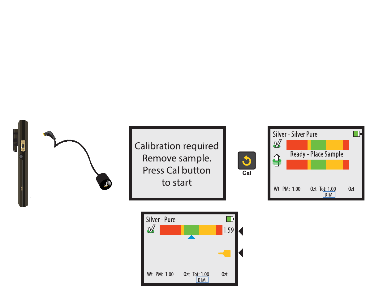
Power On and Calibrate
Power on your PMV PRO by pressing the POWER button. The device will display the serial number,
turned on. This calibration checks the internal components and prepares the device for use. Press the
CAL button to calibrate. The device will check each sensor then show the READY screen.

7
Setup
You may change some settings in the SETUP screen. To access the SETUP screen, press the RIGHT
button on the READY screen. Use the UP and DOWN buttons to select the category, and use the RIGHT
and LEFT buttons to change the selection within a category. Press the ENTER button when done to exit
the SETUP screen.
Note: You do not need to setup the device each time you use it, the settings are saved between uses.

8
Metal Selection
Prior to taking a measurement, you must select the appropriate metal or alloy from the metal selection
database. Press the button open the selection menu. Use the LEFT and RIGHT buttons to
navigate between metal categories, and use the UP and DOWN
a category. When ready, press the ENTER, , or WEIGHT

9
Weight Entry
To enter the weight of a sample, press the WEIGHT button. You can either select from the options listed
in the English Units (Ozt) and Metric Units (grams) categories, or you can manually enter a weight on
your own. Use the LEFT and RIGHT buttons to navigate between categories, and use the UP and DOWN
buttons to select options within a category. When ready, press ENTER, , or
the selection.
Manual Weight Entry
To manually enter weight, use the UP and DOWN
buttons to select the type of weight you want to enter.
Press the ENTER button to change the indicated
weight. Use the LEFT and RIGHT buttons to select the
digit and use the UP and DOWN buttons to change
the digit value. Press the or button
10
Sample consistent with
selected metal
aspects of sample, like
size, weight, and
markings.
Sample inconsistent
with selected metal
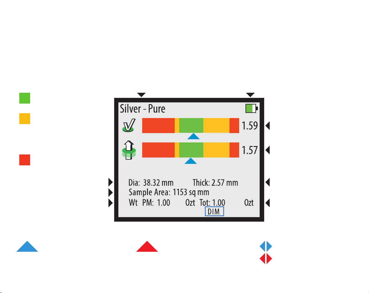
Measurement Screen
The MEASUREMENT screen will display when taking a reading. Below is a basic explanation of each
part of the screen. The screen will not display the diameter, thickness, or weight if weight mode is
Indicates the device is getting a
reliable reading.
Indicates the device is getting an
unreliable reading, treat result
with caution.
Indicates the result is off the

11
Measurement Interpretation
2.32
1.71
The device is getting a reliable reading
and the reading is consistent with the
selected metal.
The device is getting a reliable reading
that the surface of the sample is
inconsistent with the selected metal.
The device is getting a reliable reading
indicates that the bulk of the sample is
inconsistent with the selected metal.
The red arrows indicate that the
indicating a problem with the sample.
A red arrow on the top bar means the
sample is too small. Try measuring
with a smaller sensor.
A red arrow on the bottom bar means
the sample is too thin. Try measuring
with a smaller sensor.

12
Dimension Verification
To verify the dimensions of a sample, the correct metal must be selected and the correct weight must be
entered. To verify the dimensions of a sample, press the button while the device is reading
the sample. Select the shape of the sample using the UP and DOWN buttons. Once the DIMENSION
screen appears, you may move the sample away from the sensor.
• align the right edge of the sample to the vertical dotted line indicated by the
illuminated LED. The left edge of the sample is expected to fall within the green range indicated on
the screen. If the edge falls within the range, then the sample’s density is consistent with the selected
metal. If the left edge falls outside of the green range, then the sample’s density is inconsistent with
the selected metal.
• align the right edge of the sample to the vertical dotted line indicated
by the illuminated LED. Use the UP and DOWN buttons to adjust the indicated width on the screen
to match the width of the sample. While adjusting the width, the illuminated LED may change
to indicate a different vertical dotted line. Re-align the right edge of the sample to the new line.
With both the right edge and width aligned properly, the sample’s left edge should fall somewhere
within the green range. If the edge falls within the range, then the sample’s density is consistent
with the selected metal. If the left edge falls outside of the green range, then the sample’s density is
inconsistent with the selected metal.
The PRO must be actively reading a sample when is pressed to perform dimension

13
Dimension Verification Diagram
14
Wand Use
Wands are optional attachments for the PMV PRO. To use a Wand attachment, plug the Wand into the
Wand Connector on the right-hand side of the device. When you plug in the Wand, the device will ask
for calibration. Remove all samples from the device and ensure the Wand is at least one inch away from
any metal, then press the CAL button. When the READY screen is displayed, you may touch the face of
the Wand to a sample.
When measuring with the Wand, only the reading will display. There will also
be a yellow Wand indicator on the screen indicating the device is using the Wand’s sensor.
Refiners
When the Wand is touched to metal,
the screen will change to show the
results of the reading. There is only
one bar and a yellow icon appears to
indicate that the wand is in use.

15
PC Interface
The PMV PRO is capable of using a Windows PC (Windows 7, 8, 10, and 11) as an interface for the
sigmametalytics.com/pro-pc) and following the included download and installation instructions.
Once the program is successfully downloaded and installed, plug the PRO device into your PC using the
included USB cable.
To install the PRO PC interface:
1.
3. Your computer might show a warning that the .MSI was stopped from running because it might be
dangerous. Click “Learn More” and then “Run Anyway” to install the program.
4. The program will install to the C: drive by default, but you may select a custom folder.
5.
“PMV PRO.”
6. Connect your PRO to your computer using the included USB cable. Power on your device and run the
PMV PRO program to get started.
7. While using the PRO with the PC interface, the readings will display on both the device’s display and
the PC application.

16
External Bridge
The External Bridge is an optional attachment for the PMV PRO. To use the External Bridge, plug the
External Bridge into the External Bridge connector on the right-hand side of the device. When you
plug in the External Bridge, the device will ask for calibration. Remove all samples from the device and
External Bridge, and ensure the External Bridge’s plunger is in the up position. Then press the CAL
button. When the READY screen is displayed, you may place your sample under the External Bridge
may move the sample around under the plunger to test various areas.
When measuring with the External Bridge, the Basic and will display, just
like using the onboard sensors.
The sample must be no more than 45mm thick. The sample must cover the entire black circle on the
External Bridge platform throughout testing.

17
External Bridge Dimension Verification
overview. When verifying dimensions with the External Bridge, enter the measured weight, then, press the button
while the device is reading the sample. The device will display an initial DIMENSIONS screen. You must enter the measured
scale or calipers to measure the width. Once you have entered the width, press the button again and the device
For bars with angled
sides, measure width
from the middle of
each side.
Refer to Page 9 for data entry.

18
Thickness Calibration
In the event that your PRO device’s onboard sensors become miscalibrated, it may be important to re-
samples. Once the device displays the READY screen, press and hold the CAL button for 3 seconds. The
THICKNESS CALIBRATION screen will appear. Place the included calibration disk under the affected
sensor, then press the ENTER button. Leave the calibration disk under the sensor until the screen
returns to the MEASUREMENT screen.
With correct calibration, the calibration disk should be measured at about 1.60 - 1.61 mm thick. If your
device reads the calibration disk as more than 0.1 mm thinner or thicker than expected, please contact
us.
This re-calibration is only rarely needed and should only be performed if the device is showing
clear signs of a thickness mis-calibration. Because of the way the PRO electronically measures the
thickness of coins based on the face of the coin, the PRO’s indicated thicknesses for coins tends to be

Thickness Calibration
Cal
Press Cal and hold 3 seconds
Place Calibrator
under sensor.
Press Enter button
to cal
Press
Enter
When Done
Calibration
Power
CalMetal MeasureWeight
[█]
10 504540353025mm 05 2015 6055 80757065 105 110100959085 135130125120115 140
Place sample against dotted lines where indicated.
Silver-Silver Pure
Wt PM: 1.00 Ozt Tot: 1.00 Ozt
DIM
Ready - Place Sample
Place calibration
coin under each sensor that
that needs to be
calibrated
19

20
Common Questions
1.
Our “Pure Silver” range is calibrated to put .9999 silver in the green and .999 silver in the yellow on the right. We do this
because we so frequently see .999 silver counterfeited that we want all users to be cautious of .999 silver samples and
to check the other aspects (markings, weight, and size) of the sample prior to making any judgment. If you are using an
2.
The left side of the reading range indicates less resistivity and the right side indicates more resistivity. If a sample reads to
the left, it means it is less resistive than expected; if a sample reads to the right, it means it is more resistive than expected.
3.
Modern coinage is designed to have the same resistivity as older 90% silver coinage to ensure they all work in vending
machines. The best way to ensure your quarters are 90% silver is to check their weight: modern quarters are about 0.5
grams lighter than older quarters.
4.
The device needs to be actively measuring the sample when you press the MEASURE button to bring up the dimensions
5.
The device will ask for calibration when powering on and when plugging in an attachment. In regular use, we recommend re-
of all samples and press the CAL button to re-calibrate.
6.
The PMV PRO electronically measures thickness and takes the average thickness from the face of the coin while trying to
account for relief, design, and lettering. Mints and retailers measure coin thickness using calipers at the rim, not the face.
Because of this different method of measuring, the PRO’s thickness measurement is usually slightly thinner than what’s
published by the mint or retailers.
7.
The PMV PRO can go for 6 - 8 hours of constant use before needing a charge. The device has a high-capacity battery, so you
can leave it charging overnight or for long periods without damaging the system.
This manual suits for next models
1
Table of contents
Other Sigma Metalytics Measuring Instrument manuals


