SIGMA TEK RFID 131 User manual

RFID 131
RFID Reader
with USB and CAN Connection
Date of creation: 22.12.2016
Version date: 01.07.2020
Article number: 01-691-131-E

Publisher: SIGMATEK GmbH & Co KG
A-5112 Lamprechtshausen
Tel.: 06274/4321
Fax: 06274/4321-18
WWW.SIGMATEK-AUTOMATION.COM
Copyright © 2016
SIGMATEK GmbH & Co KG
Translation from German
All rights reserved. No part of this work may be reproduced, edited using an electronic system, duplicated or dis-
tributed in any form (print, photocopy, microfilm or in any other process) without the express permission.
We reserve the right to make changes in the content without notice. The SIGMATEK GmbH & Co KG is not responsi-
ble for technical or printing errors in the handbook and assumes no responsibility for damages that occur through
use of this handbook.
RFID READER RFID 131
01.07.2020 Page 1
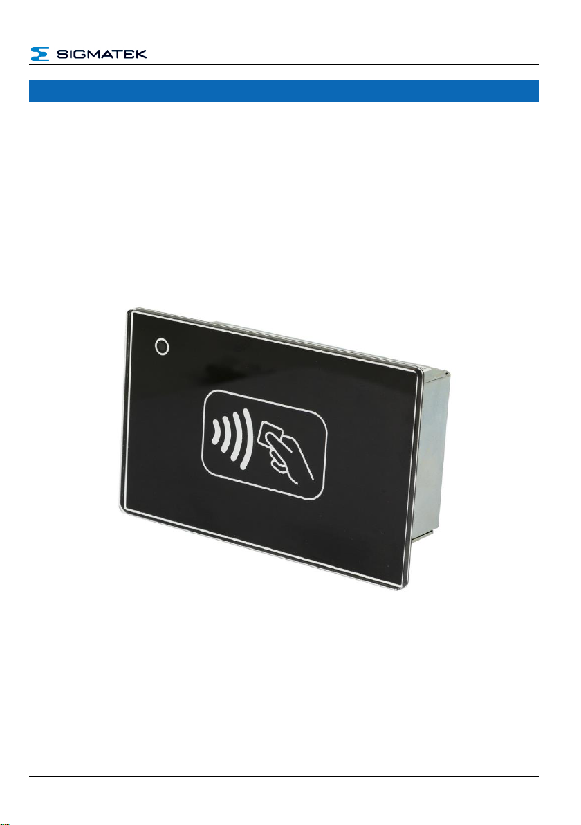
RFID Reader RFID 131
The RFID reader is an installable device for reading and writing to RFID card. Communica-
tion with other bus participants is established over the CAN bus or USB interface. The
reader is supplied with +24 V.
The RFID reader is installed in a cutaway of the control cabinet. The status LED in the
upper left corner blinks in a 1 s cycle and indicates the readiness of the device. With a CAN
message, it can also be controlled via the application.

RFID 131 RFID READER
Page 2 01.07.2020
Contents
1Technical Data ........................................................................ 4
1.1 Performance Data.........................................................................4
1.2 Electrical Requirements...............................................................4
1.3 RFID Reader ..................................................................................4
1.4 Environmental Conditions...........................................................5
1.5 Miscellaneous ...............................................................................5
2Mechanical Dimensions......................................................... 6
3Connector Layout................................................................... 7
3.1 Applicable Connectors.................................................................8
4Mounting Instructions............................................................ 9
4.1 Mounting Position ........................................................................9
5General Instructions..............................................................10
5.1 Ground.........................................................................................10
5.1 Shielding......................................................................................10
5.2 ESD Protection............................................................................10
5.3 User Guidelines ..........................................................................11
6CAN Bus.................................................................................12
6.1 Node ID Assignment...................................................................12
6.1.1 Node-IDs (CAN Open SDO)..............................................................12
6.2 Number of CAN Bus Participants .............................................13

RFID READER RFID 131
01.07.2020 Page 3
6.3 CAN Bus Data Transfer Rate .....................................................14
6.4 CAN Bus Termination.................................................................15
6.5 CAN Protocol...............................................................................15
6.5.1 CAN Object Definition....................................................................... 15
6.5.2 CAN –Object Dictionary................................................................... 16
6.5.3 Serial Interface.................................................................................. 17
6.5.4 Example Communication - Scanning Tags....................................... 17
7USB Interface Connections..................................................23
7.1 Use with Windows-based Systems...........................................23
8FCC Statement.......................................................................24
9Cleaning the Front.................................................................25
10 Disposal .................................................................................26
RFID 131 RFID READER
Page 4 01.07.2020
1 Technical Data
1.1 Performance Data
Protocol
ISO 15693, ISO 14443A, ISO 14443B
Supported cards
Mifare Ultralight/Ultralight C
Mifare Classic Mini/1K/4K
Mifare Desfire EV1 2K, 4K 8K
Mifare Pro, Plus
ISO15693 NXP ICOD SLI, TI TagIT, standard cards
RF power
100 mW EIRP
Operating frequency
13.56 MHz
Reading distance
up to 5 cm
(depending on the tag, antenna and ambient conditions)
Write distance
approximately 70 % of the read distance
Interfaces
1x USB device 2.0, (Type Mini-B)
1x CAN bus
Status LEDs
yes, blinks in 1 s frequency and indicates the readiness of the device
1.2 Electrical Requirements
Supply voltage
typically +24 V DC
minimum +18 V DC
maximum +30 V DC
Current consumption
Power supply +24 V
minimum 45 mA
maximum 60 mA
Inrush current
2 A for 2 ms
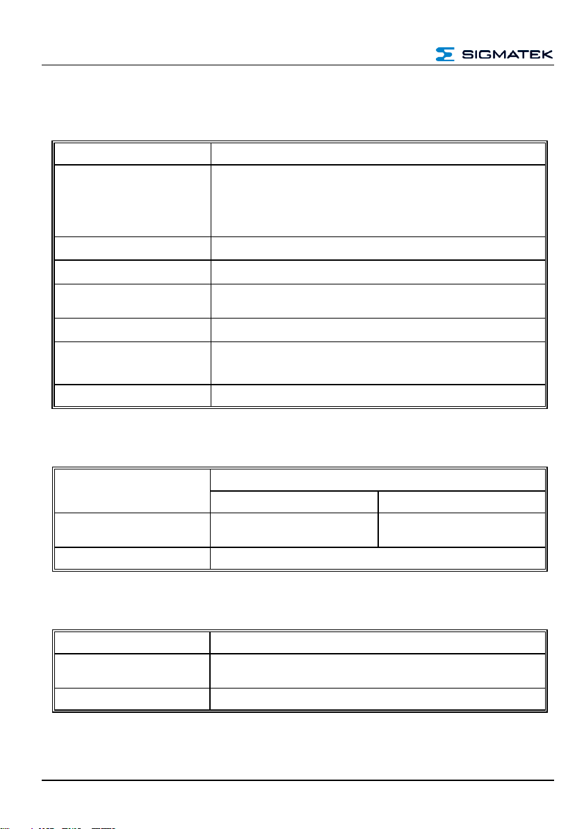
1.3 RFID Reader
Dimensions
90 x 57 x 30.8 mm (W x H x D)
Material
front: acrylic glass
back: chromated sheet steel
Weight
110 g

RFID READER RFID 131
01.07.2020 Page 5
1.4 Environmental Conditions
Storage temperature
-20 ... +85 °C
Environmental temperature
0 ... +55 °C
Humidity
0-95 %, non-condensing
EMC resistance
according to EN 61000-6-2 (industrial area)
EMC noise generation
according to EN 61000-6-4 (industrial area)
Radio Communication Conformity
Europe
according to ETSI EN 300 330 (2014/53/EU, RED Directive)
Radio Communication Conformity
USA
FCC CFR 47 Part 15
Product safety
EN 60950-1:2006
Vibration resistance
EN 60068-2-6
2-9 Hz: amplitude 3.5 mm
9-200 Hz: 1 h (10 m/s2)
Shock resistance
EN 60068-2-27
duration 11 ms, 18 Shocks
15 g (150 m/s2)
Protection type
EN 60529
protected through the housing
front: IP65
cover: IP20
1.5 Miscellaneous
Article number
01-691-131
Hardware version
2.x
RFID 131 RFID READER
Page 6 01.07.2020
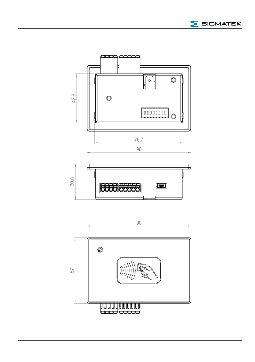
2 Mechanical Dimensions
RFID READER RFID 131
01.07.2020 Page 7
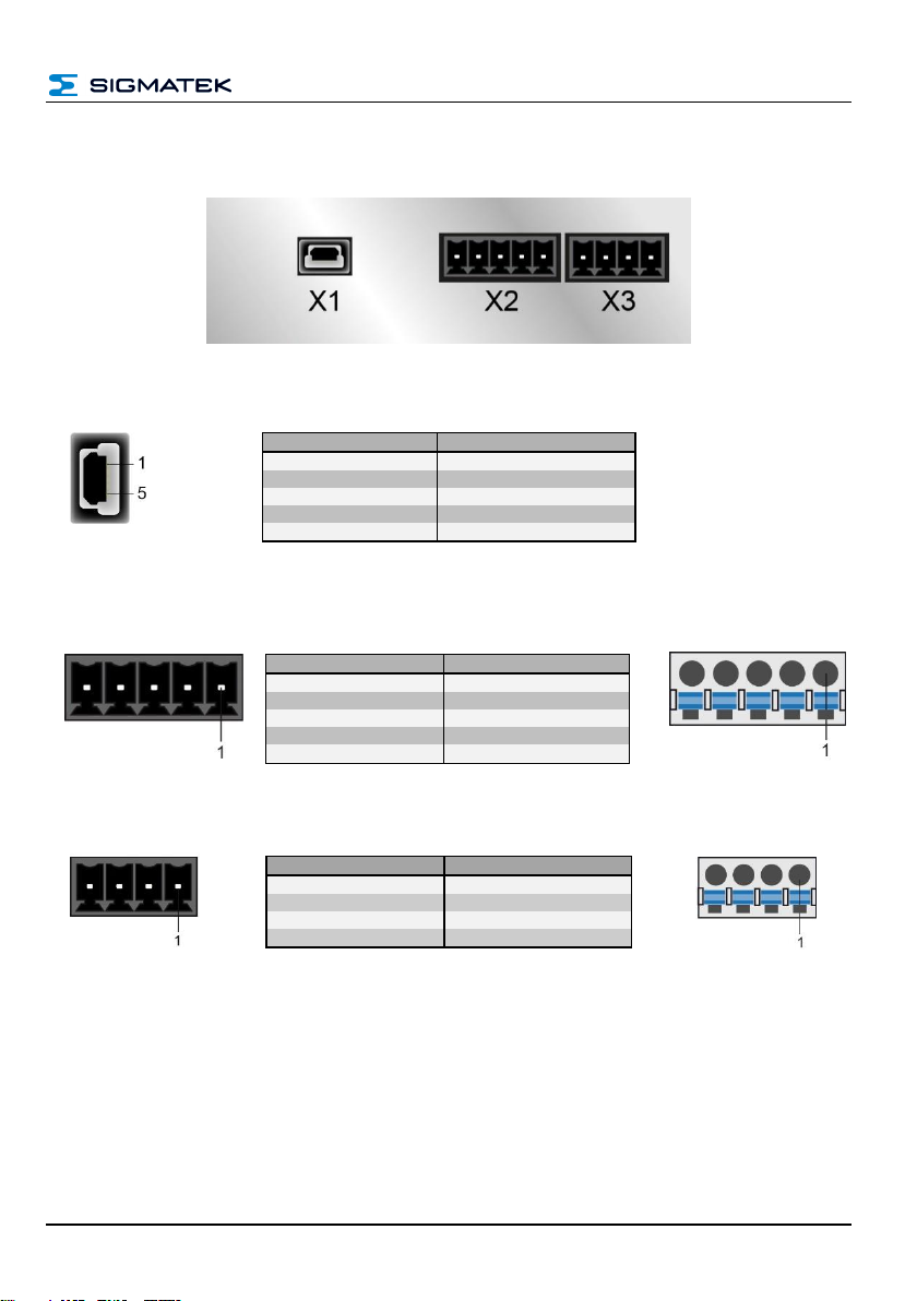
3 Connector Layout
X1: USB-Device 2.0 (Type Mini-B)
n.c. = do not use
X2: CAN Bus (5-pin Phoenix Contact)
X3: Visualization (4-pin Phoenix Contact)
Pin
Function
1
+5 V
2
D-
3
D+
4
n.c.
5
GND
Pin
Function
1
CAN A (LOW)
2
CAN B (High)
3
CAN A (CAN LOW)
4
CAN B (High)
5
CAN GND
Pin
Function
1
+24 V supply
2
+24 V supply
3
GND
4
GND

RFID 131 RFID READER
Page 8 01.07.2020
S1: DIP-Switch
3.1 Applicable Connectors
Connectors:
X1: USB Type Mini-B on a USB Type A cable, max. length 3 m
(not included in delivery)
X2: 5-pin Phoenix plug with spring terminals FK-MCP 1.5/ 5-ST-3.5
(Included with delivery)
X3: 4-pin Phoenix plug with spring terminals FK-MCP 1.5/ 5-ST-3.5
(Included with delivery)
Connections:
Stripping length:
10 mm
Mating direction:
parallel to the conductor axis or circuit board
Conductor cross section rigid:
0.2-1.5 mm2
Conductor cross section flexible:
0.2-1.5 mm2
Conductor cross section AWG/kcmil:
24-16
Conductor cross section flexible with
ferrule without plastic sleeve:
0.25-1.5 mm2
Conductor cross section flexible with
ferrule with plastic sleeve:
0.25-0.75 mm2 (reason for reduction d2 of the
ferrule)

RFID READER RFID 131
01.07.2020 Page 9
4 Mounting Instructions
The following guidelines must be observed when installing the RFID reader:
- For installation with the screw-in brackets provided, it is recommended that the in-
stallation panel have a material strength of 3 mm. Material strengths from 1 to 4
mm are also allowable. The screw-in brackets can be tightened with a maximum
torque of 0.15 Nm. For this purpose, a 3x0.5 flat-tip screw driver is required.
- To avoid damage to the front, it is important to ensure that during installation, the
mounting surface clean (free of debris, uneven areas). Unevenness can lead to
voltages on the front or contamination from dust and water.
4.1 Mounting Position
Since very little heat is generated, no specific clearance is required.
Sufficient air circulation however, must be ensured so that no trapped heat can developed.
Section side view: section top view

RFID 131 RFID READER
Page 10 01.07.2020
5 General Instructions
5.1 Ground
The RFID reader must be connected to ground through the assembly on the control cabinet
or over the connection provided. It is important to create a low-ohm ground connection, only
then can error-free operation be guaranteed. The ground connection should have a maxi-
mum cross section and the largest (electrically conductive) surface possible.
5.1 Shielding
To wire the USB interface, a USB 2.0 cable must be used. When using the CAN bus inter-
face, a shielded cable must be used. Noise signals can therewith be prevented from reach-
ing the electronics and affecting the function.
5.2 ESD Protection
Before any device is connected to, or disconnected from the reader, the potential should be
equalized (by touching the control cabinet or ground terminal). This will allow the dissipation
of electrostatic loads (caused by clothing/shoes).

RFID READER RFID 131
01.07.2020 Page 11
5.3 User Guidelines
CAUTION!
The RFID reader cannot always be operated with an interface (USB or CAN). Simulta-
neous operation is not supported and causes the reader to malfunction.
CAUTION!
The USB interface is not used to operate the device.
Here, as can be seen under "Electrical Requirements", an additional external voltage
supply is required.
Technical changes to the device, as well as improper use can lead to the loss of the
FCC license and generate interference, which can affect the function of nearby de-
vices.
Please note the national standardization when operating the wireless device.
Further information on the use, as well technical data can be found in the separate manual
for the RFID reader series. This can be acquired through the support.

RFID 131 RFID READER
Page 12 01.07.2020
6 CAN Bus
This section explains how to correctly configure and use the CAN bus. The CAN bus inter-
face is based on the CAN-Open standard according to EN50325-4. For the configuration,
the device ID and the data transfer rate must be set.
6.1 Node ID Assignment
Each CAN bus participant in the system is assigned its own node identification number
(Node ID). With this Node ID, data can be exchanged with other stations connected to the
bus. In a CAN bus system however, each Node ID can only be assigned once!
6.1.1 Node-IDs (CAN Open SDO)
SW 4
SW 5
SW 6
SW 7
SW 8
Node ID
Off
Off
Off
Off
Off
1
On
Off
Off
Off
Off
2
Off
On
Off
Off
Off
3
On
On
Off
Off
Off
4
Off
Off
On
Off
Off
5
On
Off
On
Off
Off
6
Off
On
On
Off
Off
7
On
On
On
Off
Off
8
Off
Off
Off
On
Off
9
On
Off
Off
On
Off
10
Off
On
Off
On
Off
11
On
On
Off
On
Off
12
Off
Off
On
On
Off
13
On
Off
On
On
Off
14
Off
On
On
On
Off
15
On
On
On
On
Off
16

RFID READER RFID 131
01.07.2020 Page 13
Off
Off
Off
Off
On
17
On
Off
Off
Off
On
18
Off
On
Off
Off
On
19
On
On
Off
Off
On
20
Off
Off
On
Off
On
21
On
Off
On
Off
On
22
Off
On
On
Off
On
23
On
On
On
Off
On
24
Off
Off
Off
On
On
25
On
Off
Off
On
On
26
Off
On
Off
On
On
27
On
On
Off
On
On
28
Off
Off
On
On
On
29
On
Off
On
On
On
30
Off
On
On
On
On
31
On
On
On
On
On
32
6.2 Number of CAN Bus Participants
The maximum number of participants on the CAN bus depends on the cable length, termi-
nation resistance, data transfer rate and the drivers used in the participants.
With a termination resistance of 2x 20 , a minimum of 100 participants are possible.
RFID 131 RFID READER
Page 14 01.07.2020
6.3 CAN Bus Data Transfer Rate
Various data transfer rates (baud rates) can be set on the CAN bus. The longer the bus line
is, the lower the data transfer rate that must be selected.
In delivery condition, the CAN Baud rate is set to 500 kbits/s.
The CAN bus transfer rate can be freely configured via DIP switch, if a device is ex-
changed or incorrectly configured, the DIP switch must be checked or set correctly.
SW 1
SW 2
SW 3
Mmximum length
Baud rate (in kBaud)
Off
Off
Off
60 m
615
On
Off
Off
80 m
500
Off
On
Off
160 m
250
On
On
Off
320 m
125
Off
Off
On
400 m
100
On
Off
On
800 m
50
Off
On
On
1200 m
20
On
On
On
30 m
1000
These values are valid for the following cable: 120 , Twisted Pair.
Note: For the CAN bus protocol: 1 kbits/s = 1 kBaud
RFID READER RFID 131
01.07.2020 Page 15
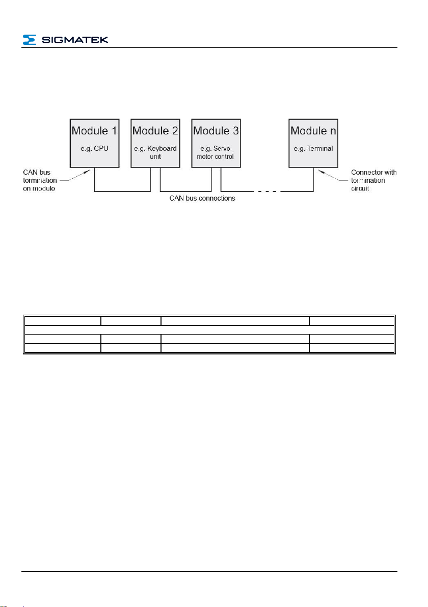
6.4 CAN Bus Termination
In a CAN bus system, both end modules must be terminated. This is necessary to avoid
transmission errors caused by reflections in the line.
6.5 CAN Protocol
Each message contains up to 8 bytes. The data transfer takes place according to CiA
DS301. Several CAN messages may be necessary for one frame on the RFID reader.
6.5.1 CAN Object Definition
Direction from the point of view of the control controlling the module.
Object Number
Direction
Name
Cycle Time
SDO
0x580 + Node ID
Receive
SDO request
not cyclic
0x600 + Node ID
Transmit
SDO response
not cyclic

RFID 131 RFID READER
Page 16 01.07.2020
6.5.2 CAN –Object Dictionary
Index
(hex)
Subindex
Size
(bytes)
Access
Description
2000
0
256
SEG_WO
RFID –Request
2002
0
1
EXP_RO
Number of FW information entries (here: 4)
2002
1
2
EXP_RO
FW version
2002
2
4
EXP_RO
Serial number of the product
2002
3
16
SEG_RO
Product name in ASCII
2002
4
2
EXP_RO
Bootloader version
2003
0
1
EXP_WO
Special commands
0xE0 … Switch to bootloader
(e.g. for FW update)
0xF0 … Hard reset of the RFID reader
(This command entry in the Object Dictionary is
reset in the firmware immediately after recogni-
tion)
2005
0
4
EXP_RW
LED Access:
Bit 0 –Bit 13: switch on time in ms (0 bis 16383)
Bit 14 –Bit 27: switch off time in ms (0 bis 16383)
Bit 28: Direct control
0 … LED off
1 … LED on
Bit 29: Blink-enable
0 … Direct control is used
1 … The LED flashes at the indicated times
(Direct control is ignored)
Bit 30 –Bit 31: Reserved
2200
0
256
SEG_RO
RFID –Response (the actual length returned in
the initiate segmented read packet varies with the
length of the RFID reader response (max. 256
bytes))
Accesses from the point of view of the control that controls the module:
SEG_WO .. segmented write only access
SEG_RO .. segmented read only access
EXP_WO .. expedited write only access
EXP_RO .. expedited read only access
EXP_RW .. expedited read/write access

RFID READER RFID 131
01.07.2020 Page 17
6.5.3 Serial Interface
The data from and to the RFID hardware (2000 RFID - Request, 2200 RFID - Response)
are forwarded by the microcontroller from/via the serial interface. The protocol documenta-
tion of the HF-RFID Reader can be obtained separately from the support department. It
describes the complete communication processes.
6.5.4 Example Communication - Scanning Tags
Here a short communication example is shown which CAN messages are necessary to
perform a SCAN.
To read or write data from or to the RFID reader, the protocol must be transferred from the
HF-RFID reader via the CanOpen protocol.
Message to the RFID Reader:
Byte
Data
Description
0
0x21
CANOpen Header (structure see CANOpen Specification) →Command “initiate down-
load request”
1
0x00
2 Byte Index (see Object Dictionary) →0x2000 = RFID request according to Object
Dictionary
2
0x20
3
0x00
1 Byte Subindex (see Object Dictionary)
4
0x06
Data (structure see CANOpen Specification (different depending on command).
In our case the length of the “Scaan Tags" command is given here
5
0x00
6
0x00
7
0x00
Response from the RFID Reader:
Byte
Data
Description
0
0x60
CANOpen Header … command “initiate download response”
1
0x00
2 Byte Index
2
0x20
3
0x00
1 Byte Subindex
4
0x00
Reserved (always 0)
5
0x00
6
0x00
7
0x00

RFID 131 RFID READER
Page 18 01.07.2020
After the reader has confirmed the message, the next message is sent.
Message to the RFID Reader:
Byte
Data
Description
0
0x03
CANOpen Header (structure see CANOpen Specification) →Command “download
segment request”
1
0x00
Here follows the data (in this case the Scan Tags command of the reader)
Byte 1… command “Scan Tags”
Byte 2… Status code to reader (always 0x00)
Byte 3-4 … length of the data
Byte 5 … card type
Byte 6 …CRC
Byte 7 … not used →0x00
2
0x00
3
0x01
4
0x00
5
0x02
6
0x03
7
0x00
Response from the RFID Reader:
Byte
Data
Description
0
0x20
CANOpen Header … command “download segment response”
1
0x00
Reserved (always 0)
2
0x20
3
0x00
4
0x00
5
0x00
6
0x00
7
0x00
Now the Scan Tags command should have been successfully sent to the firmware of the
RFID reader via the CanOpen protocol. To be able to read the response to the Scan Tags
command we have to read the response from the module. The response of the command is
provided by the firmware in the designated area (0x2200 RFID Response) in the object
dictionary.
An SDO upload must be initiated to read this data.
Table of contents


