Sigma IRIS Lite User manual

1
Installation Manual
IRIS Lite & IRIS Basic
Outdoor Self Powered Sirens

2

3
• Τhe siren installation and the wiring can be completed without applying power from the control
panel and remain so for a long time. It is activated by applying the supply voltage powered from
the control panel. This feature is particularly useful in cases of a building, where the siren is first
installed and the panel is powered after a long time. In this case, the siren’s consumption is
8 mA, the flash is not active to indicate standby mode and the siren will be switched on by the
first application of the supply voltage from the control panel.
• In standby mode, there are seven different - selected - modes of operation of the five Flash
LEDs.
• It has five different alarm sounds (selectable).
• It has two independent activation inputs, which operate with a positive or negative voltage
interruption.
• The siren follows the alarm duration of the control panel. However, the siren will also gives an
alarm, if the cables that connecting the siren to the panel, are cut-off or shorted.
Specifically:
- gives a five (5) minutes alarm, if only the power supply cables are cut-off (+12 V)
- gives a fifteen (15) minutes alarm, if only the TRIGGER cable is cut-off
- gives a five (5) minutes alarm, if both the power supply cables and TRIGGER cable are cut-off
simultaneously
• It has short circuit protection on the battery charging (of the cables) output.
• It has protection against faulty connection of the battery poles with simultaneous optical LED
indication.
• When the siren is in standby mode and its battery voltage drops bellow10.0 V, flash stops
flashing.
• It has a TAMRER to protect it from opening the outer cover and / or detachment from the wall
The Tamper switch has free contacts for easy connection to the control panel.
• Built-in FLASH, with five high brightness and low power LEDs with short-circuit protection.
These LEDs are flashing in various programmable modes when the siren is at standby mode.
General specifications
Description
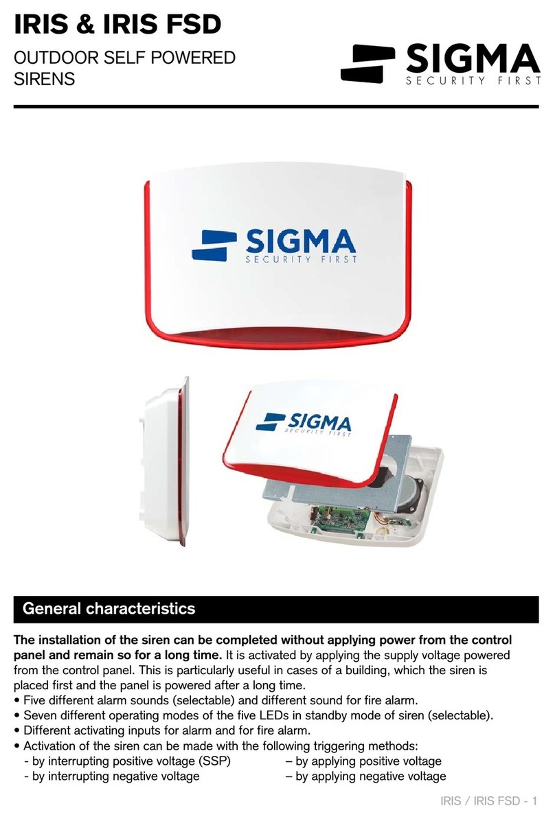
Self-powered and self-protective electronic siren with built-in FLASH, in two shades (red and
blue), for easy detection of the area from which the alarm comes. It is an ideal combination of
stylish design and quality construction and is manufactured under the strictest safety standards.
The outer casing is made of high-strength polycarbonate, suitable for outdoor use. Inside it is pro-
tected by a metal cap made of galvanized sheet metal (in the Basic version) and it has protection
against opening the outer lid or detaching the siren from the wall.

4
Technical Specifications IRIS LITE IRIS BASIC
Power Supply 13.2-14.5 V DC
Operational Voltage 13.8 V DC
Consumption (Standby MODE) 8mA (when powered for the first time only by the battery
and is not fed by the control panel)
Consumption (Standby MODE) 13.0mA when the LEDs turn on at standby mode
Consumption (Standby MODE) 9.5mA when the LEDs do not light up in standby mode
Consumption (Alarm MODE) 1.2A max only sound, 1.35Α max when the FLASH turns
on
Consumption LED FLASH 150mA max
Activation from Trigger +
It is balanced when the Trigger + input has a +12VDC
permanently. It sounds an alarm if this voltage is inter-
rupted or when the voltage at this input is <5.8 V DC
Activation from Trigger-
It is balanced when the Trigger - input is permanently at
0 (- of the power supply) and gives an alarm when the
supply is cut off or when the input voltage is> 1.5 V DC
Operation Frequency 900-2700 Hz
Acoustic Power 122dB at 1 meter
Maximum Alarm Duration 15 minutes
Tamper Protection On the cover and on the wall
ΤΑΜΡΕR contacts (NC-NO) 600mA / 12.5 V DC
Protection Rate IP 44
Battery (Pb) 12 V /1.3 or 2.3 Ah
Siren housing and Flash material Polycarbonate
Metal protection cover NO YES
Weight (without battery) 1460 gr 1880 gr
Dimensions 348 x 245 x 78 mm (WxHxD)

5
Connecting the siren’s TAMPER to the Control Panel
At the “TAMPER” terminals, the Tamper contacts of the siren end up. When the siren is screwed
to the wall and its lid is closed, this output is NC and becomes NO when the lid is opened or
the siren detaches from the wall. These contacts can be connected to any perimeter or 24-hour
zone of the panel (such as NC or EOL zone, using EOL resistor), taking care to use the correct
polarity (COM & ZONE).
Caution!
If you use an EOL band, then, for greater security, place the EOL resistor in the siren,
at the TAMPER ZONE output and in series with the cable as shown in the wiring
diagram.
Power supply of the siren
The + 12V inputs are for powering the siren and charging the battery. They are connected to the
corresponding outputs of the Control panel, taking care of the correct polarity.
Caution!
For the siren to function properly, a battery must be used. In the case, however, that
you want the siren without battery to operate, you must connect the red battery cable
to + 12V. The siren can operate this way, provided the cable’s cross-section allows it
and the panel power supply is able to provide the required current.
Selecting the activation method of the siren
The TRIGGER (+ or -) inputs are used to activate the siren.
Activation can be done in two modes:
A. By positive voltage interruption
Connect the “+ TRIGGER” input of the siren to the corresponding output of the Control Panel
or a programmable output (PGM), that provides 12.0V at standby mode and cut or turns to 0 V
when an alarm is given.
B. By negative voltage interruption
Connect the “- TRIGGER” input of the siren to the corresponding output of the Control Panel
or a programmable output (PGM), that provides 0V at standby mode and become an Open
Collector or turns to 12.0 V when an alarm is given.
Note: The siren follows the alarm duration of the Control panel. However, if the cables
connected to the panel are interrupted or shorted, the siren activates an alarm for a
maximum of 5 minutes.
TAMPER
COM | ZONE FREE TAMPER SWITCH CONTACTS
12V
- +
POWER SUPPLY INPUT (12V) FOR SIREN ΑΝD FOR BATTERY CHARGING
TRIGGER
- +
NEGATIVE OR POSITIVE ALARM ACTIVATION INPUT (PANEL CONTROLABLE)
Terminals Description

6
To install the siren, please follow the steps, as described below:
1. Select the point where you will mount the siren, which should be as high as possible so that
the siren is easily visible and safe.
2. Align the siren mount to the wall,with the built-in spirit level, mark the fixing holes and open
them with a drill.
3. Fix the base of the siren to the wall using the existing brackets.
4. Pass the cable that connects the siren to the panel, from the hole in the siren base. For
greater security, choose the passage of the wire inside the siren to be directly behind this
hole.
5. Connect the siren to the panel, according to the explanation of the connection terminals on
page 5 and the following wiring diagram.
6. When you finish cable connections, connect the battery to the siren. The siren can remain in
this condition until you finish the installation. The siren will start to operate normally only when
supplied with power from the alarm control panel.
Note:
When the power supply is first applied from the panel to the siren, a short sound will be heard
as a confirmation that the siren has been activated.
7. Install the inner cover and screw it in with the four corresponding screws.
8. Close siren’s external cover and fasten it with the corresponding screws.
Attention!
To power the siren from the alarm panel, you must, anyway, use cable 0,5-0,75mm2.
A 2x0.50 + 4x0.22 mm2cable is recommended.
Installation
Η γραμμή αυτή δεν είναι
απαραίτητο να συνδεθεί.
It is not necessary
to connect this this
wire wire

7
Programming the Siren
Battery Fault output
The siren functions are programmed using the “MENU” and “SELECT” buttons, which are placed
on the siren board.
Entering the programming process
To enter the siren programming process, turn on the siren by connecting the battery to the cor-
responding terminals, making sure to use the correct polarity.
Then press and hold the “MENU” button until the confirmation signal (five beeps) is heard and the
“SOUND” LED lights up.
Siren Sound Selection
When the “SOUND” LED lights up, use the “SELECT” button to select the sound you want the
siren to hear. Every time you press the “SELECT” button, the sound of the siren will be changed,
which you will hear at low volume from the speaker. The last sound you hear will be the new
sound of the siren.
Press “MENU” button to save settings and go to next menu. The LED with “FLASH”
indication will turn on.
Select the siren’s lighting at standby mode
When the “FLASH” LED lights, use the “SELECT” button, to select the lighting mode of the siren
at standby mode or even disable it. Each time you press “SELECT” button, will change the for-
mat of movement LEDs of the siren. The form of movement that, you will see at the LEDs, is the
one, the siren will follow. When all the LEDs are off, the siren will have no lighting at standby
mode.
Press “MENU” button to save settings.
Exit Setup
To exit the programming procedure, press continuously “MENU” button until the confirmation
signal (five BEEP) is heard. Immediately, the siren will enter the standby mode.
The siren will also automatically exit programming and will return to standby mode after three
minutes without pressing either button.
Factory Programming
To restore the factory settings of the siren, press simultaneously “MENU” and “SELECT” buttons
for 2 seconds until you hear the confirmation sound – ( 5 BEEP).
The siren automatically monitors the battery status (Battery Self-Test) by dynamically checking
the battery every hour when there is a voltage at the siren power input (+ 12V-) or every five min-
utes when there is no voltage. If, during the test, the battery voltage is lower than 11.5V, we have
a low battery voltage while, if the battery voltage is below 10.0V, we have a battery failure.
In both cases, the siren flash is activated as follows: initially, the middle LED of the flash turns on,
then it turns off and the next two turn on and finally, they turn off and the two external LEDs turn
on. This process is repeated until the battery voltage rises above 11.5V or the battery is replaced
with a new one and returns to standby mode again for the next test.
1.
2.
3.
4.

8
Thank you for selecting our products which have been designed and manufactured to offer you security and
safety for many years. They have been thoroughly tested before reaching your hands, and have passed all
necessary performance tests. All our products are covered by a 6 (SIX) years warranty, for good operation,
from the date of purchase and covers the products that are accompanied by invoice or receipt of purchase.
This warranty covers the free of charge repair of the device (parts and labor) in case the malfunction is due to
failure of device itself and not if the failure is cause to any wrong installation, improper use or external factors
such as lightning, floods, excess power voltage etc. Warranty ceases to exist if the device has been installed
or repaired by an unauthorized person. Also, this warranty does not cover the losses, failures or injuries
that might happen to the secured area, in case of miss operation of the device. Finally, our company is not
responsible for the correct installation and use of the security system, for which solely responsible is the
installer.
RECYCLING
Do not dispose of this device or battery in a household waste bin!
• The electrical and electronic equipment used must be handled separately and in
accordance with the legislation, which requires appropriate processing and recycling of
the aforesaid goods.
• The battery contains pollutants and, therefore, after the end of its lifetime, it should not
be disposed of in common waste but delivered to the appropriate operator for the
collection and disposal of polluting waste in accordance with the local laws and
regulations.
• Recycling of the product will help to avoid potential adverse effects on the environment
and human health, which could arise from inadequate waste management.
www.sigmasec.gr
You will need to check the proper functioning of the siren at regular intervals to make sure that the
siren is not damaged and that it will work normally when needed.
The following functions should be checked in every maintenance:
1. Check the proper operation of the siren’s speaker as well as the LED Flash by simulating an
alarm from the Control Panel.
2. Check the proper functioning of Tamper switch that protect the siren from opening or
detachment from the wall.
3. Check whether the siren’s battery voltage is 13.2-13,8 V. If the battery voltage is less than this,
replace the battery and plug new, ensuring the correct polarity.
4. Check for water or insect influx signs inside the siren and clean them if necessary.
Maintenance
Warranty
This manual suits for next models
1
Table of contents
Other Sigma Security System manuals