Signaltec MCTS II User manual

MA MCTS II, Ver. 1.4 1 11/2018
SIGNALTEC GmbH, Reutersbrunnenstrasse 27, D-90429 Nürnberg, GERMANY, T. +49 911 2550993-0, F. +49 911 2550993-13, Email: [email protected], Web: www.signaltec.com
MCTS II
Multi Channel Current Transducer System
Installation Manual

MA MCTS II, Ver. 1.4 2 11/2018
SIGNALTEC GmbH, Reutersbrunnenstrasse 27, D-90429 Nürnberg, GERMANY, T. +49 911 2550993-0, F. +49 911 2550993-13, Email: [email protected], Web: www.signaltec.com
Contents
1. Introduction
2. Receiving of goods
3. Hardware Installation
3.1. Connection of the current sensor to the MCTS rack
3.2. Connection of the current output to an instrument current input terminal
3.3. Connection of the optional voltage output to an instrument voltage input terminal
4. Operating instructions
5. Scaling
5.1. Current output ratio
5.2. Sensor output ratio when using the passive plug-on resistors
5.3. Sensor output ratio when using the active plug-on voltage amplifiers
6. Status readout interface
6.1. Pin-out of the 25-pole D-SUB
7. Specifications
7.1. Rack specifications
7.2. Transducer specifications
7.2.1. Transducers with rms-range
7.2.2. Transducers with peak-range
7.3. Connection cable specifications
7.3.1. Standard Connection Cables
7.3.2. Total Measuring Resistance at Full Scale
7.3.3. Maximum Burden Resistor depending on Transducer and Connection Cable
7.4. Burden module specifications
7.4.1. Passive plug-on burden resistor specifications
7.4.2. Active plug-on voltage amplifier specifications
8. Switching off and deinstallation
9. Installation of internal power supplies (channel extension)
10. Accessories

MA MCTS II, Ver. 1.4 3 11/2018
SIGNALTEC GmbH, Reutersbrunnenstrasse 27, D-90429 Nürnberg, GERMANY, T. +49 911 2550993-0, F. +49 911 2550993-13, Email: [email protected], Web: www.signaltec.com
1. Introduction
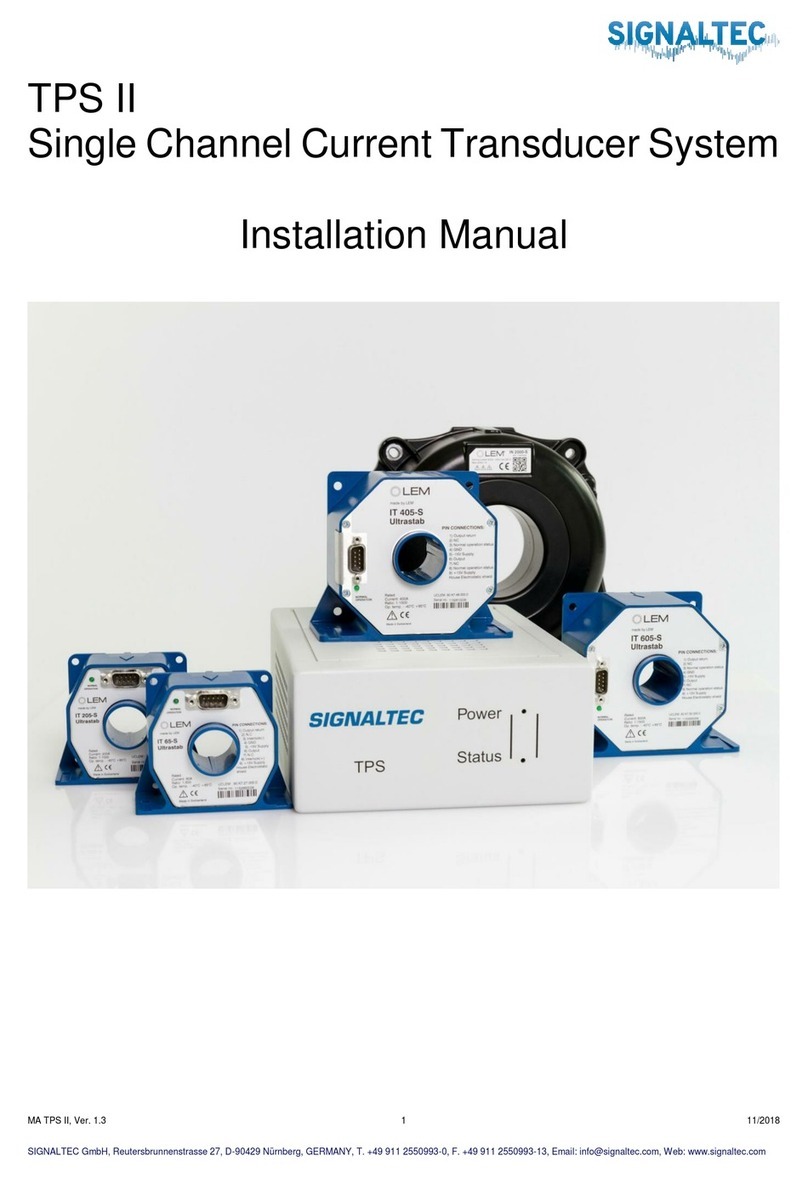
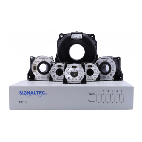
The MCTS is a multichannel high precision current transducer system, mainly used for the range extension of
power meters. The rack can be equipped with up to six internal power supplies. All internal power supplies are
galvanic isolated from each other and from earth potential. The current output terminals deliver the transducer
output current on the back panel. Passive plug-on burden resistors and active plug-on voltage amplifiers are
available as an option. The status-readout-interface delivers the transducer status (ok or overload/error) bymeans
of internal galvanic isolated relay contacts.
Warning
Please be aware that an unpowered transducer or a transducer used with open output can be destroyed. The
same can happen if a transducer is heavily overloaded. Power and transducer status are visible on the front panel.
The information of the status-readout-interface on the back panel can be used to switch off the primary current
via a relay or a PLC in case the transducer is overloaded, the MCTS is switched off or the output loop is
interrupted. All these events will change the transducer status to error on the front panel led and the status-
readout-interface. There is more information about the status-readout-interface available in chapter 6.
2. Receiving of goods
The MCTS system can be equipped with up to six internal power supplies. There are various transducer types
available from 60 A up to 2000 A. Connection cables are available in different lengths. Passive plug-on shunts
and active plug-on voltage modules are available as an option. A status-readout cable and different current and
voltage output cables are available as options either.
Please compare your order papers with our packing list and the received goods.

MA MCTS II, Ver. 1.4 4 11/2018
SIGNALTEC GmbH, Reutersbrunnenstrasse 27, D-90429 Nürnberg, GERMANY, T. +49 911 2550993-0, F. +49 911 2550993-13, Email: [email protected], Web: www.signaltec.com
3. Hardware Installation
The MCTS is delivered with rack mounting brackets for the easy installation into a 19" cabinet. The mounting
brackets can be installed easily with four screws on the left and right side panel. The 19" rack mounting brackets
and the screws are delivered with the system.
3.1. Connection of the current sensor to the MCTS rack
The current transducer will be connected to the MCTS rack with
the delivered D-SUB current transducer connection cable.
3.2. Connection of the current output to an instrument current input terminal
The transducer output current can be directly connected to the
current input terminals of a current or a power meter.
3.3. Connection of the optional voltage output to an instrument voltage input terminal
Before you connect the current output to the voltage input terminal
of a voltage meter or the sensor input terminal of a power meter
you have to transfer the output current into a voltage signal. For
this purpose, passive plug-on burden resistors and active plug-on
output voltage amplifiers are available.

MA MCTS II, Ver. 1.4 5 11/2018
SIGNALTEC GmbH, Reutersbrunnenstrasse 27, D-90429 Nürnberg, GERMANY, T. +49 911 2550993-0, F. +49 911 2550993-13, Email: [email protected], Web: www.signaltec.com
4. Operating instructions
Before you switch on the primary current through the current transducer, be sure that the transducer is powered
by the MCTS rack and that the output current loop is closed. An unsupplied transducer can be damaged as well
as a sensor with open current output loop. The power and transducer states (ok or error/overload) are visible on
the front panel and available on the status-readout interface (see chapter 6).
Power-LED off: System not powered or channel not installed
Power-LED green: Channel powered
Status-LED off: System not powered or channel not installed
Status-LED green: Transducer connected, normal operation
Status-LED red: Transducer overloaded or interruption in output circuit, switch primary current off!
Example: Four channel MCTS system
Channel 1, 2, 3: Transducer powered, transducer status ok
Channel 4: Transducer powered, transducer overloaded, output loop open or transducer defective
Channel 5, 6: No power supply installed

MA MCTS II, Ver. 1.4 6 11/2018
SIGNALTEC GmbH, Reutersbrunnenstrasse 27, D-90429 Nürnberg, GERMANY, T. +49 911 2550993-0, F. +49 911 2550993-13, Email: [email protected], Web: www.signaltec.com
5. Scaling
Various transducer types are available for the MCTS system. The older types of transducers (IT x0-S) are
specified for a maximum DC- or peak-range. To calculate the AC rms-range of the sensor you have to divide the
DC- or peak range by the square root of 2. The newer transducer types (IT x5-S and IN) are specified for a
maximum rms- and DC-Range. You can find the detailed transducer specification in chapter 7.2.
5.1. Current output ratio
Transducer
DC-Range
rms-range
Ratio
Scaling Factor
IT 65-S
60 A
60 A
60A/100mA
600 : 1
IT 205-S
200 A
200 A
200A/200mA
1000 : 1
IT 405-S
400 A
400 A
400A/266.67mA
1500 : 1
IT 605-S
600 A
600 A
600A/400mA
1500 : 1
IN 1000-S
1000 A
1000 A
1000A/666.67mA
1500 : 1
IN 2000-S
2000 A
2000 A
2000A/1000mA
2000 : 1
IT 60-S
60 A
42 A
60A/100mA
600 : 1
IT 200-S
200 A
141 A
200A/200mA
1000 : 1
IT 400-S
400 A
282 A
400mA/200mA
2000 : 1
IT 700-S
700 A
495 A
700A/400mA
1750 : 1
IT 1000-S/SP1
1000 A
707 A
1000A/1000mA
1000 : 1
5.2. Sensor output ratio when using the passive plug-on resistors
Transducer
DC-Range
rms-range
Plug-on
Burden
Resistor
Ratio
Scaling Factor
IT 65-S
60 A
60 A
MCTS/BR25/0.01
60A/2.5V
41.667 mV/A
IT 205-S
200 A
200 A
MCTS/BR10/0.01
200A/2V
10.000 mV/A
IT 405-S
400 A
400 A
MCTS/BR10/0.01
400A/2.667V
6.667 mV/A
IT 605-S
600 A
600 A
MCTS/BR2.5/0.02
600A/1V
1.667 mV/A
IN 1000-S
1000 A
1000 A
MCTS/BR1.5/0.02
1000A/1V
1.000 mV/A
IN 2000-S
2000 A
2000 A
MCTS/BR1/0.02
2000A/1V
0.500 mV/A
IT 60-S
60 A
42 A
MCTS/BR50/0.01
60A/5V
83.333 mV/A
IT 200-S
200 A
141 A
MCTS/BR25/0.01
200A/5V
25.000 mV/A
IT 400-S
400 A
282 A
MCTS/BR1/0.02
400A/0.2V
0.500 mV/A
IT 700-S
700 A
495 A
MCTS/BR1/0.02
700A/0.4V
0.571 mV/A
IT 1000-S/SP1
1000 A
707 A
MCTS/BR1/0.02
1000A/1V
1.000 mV/A
5.3. Sensor output ratio when using the active plug-on voltage amplifiers
Transducer
DC-Range
rms-range
Plug-on
Burden
Resistor
Ratio
Scaling
Factor
IT 65-S
60 A
60 A
MCTS/VM0.1/0.02
60A/7V
116.667 mV/A
IT 205-S
200 A
200 A
MCTS/VM0.2/0.02
200A/7V
35.000 mV/A
IT 405-S
400 A
400 A
MCTS/VM0.26/0.02
400A/7V
17.500 mV/A
IT 605-S
600 A
600 A
MCTS/VM0.4/0.02
600A/7V
11.667 mV/A
IN 1000-S
1000 A
1000 A
MCTS/VM0.66/0.02
1000A/7V
7.000 mV/A
IN 2000-S
2000 A
2000 A
MCTS/VM1/0.02
2000A/7V
3.500 mV/A
IT 60-S
60 A
42 A
MCTS/VM0.1/0.02
60A/7V
116.667 mV/A
IT 200-S
200 A
141 A
MCTS/VM0.2/0.02
200A/7V
35.000 mV/A
IT 400-S
400 A
282 A
MCTS/VM1/0.02
400A/1.4V
3.500 mV/A
IT 700-S
700 A
495 A
MCTS/VM1/0.02
700A/2.8V
4.000 mV/A
IT 1000-S/SP1
1000 A
707 A
MCTS/VM1/0.02
1000A/7V
7.000 mV/A

MA MCTS II, Ver. 1.4 7 11/2018
SIGNALTEC GmbH, Reutersbrunnenstrasse 27, D-90429 Nürnberg, GERMANY, T. +49 911 2550993-0, F. +49 911 2550993-13, Email: [email protected], Web: www.signaltec.com
6. Status readout interface
Status-Readout-Interface
The channel and transducer states are visible on the MCTS
front panel and can be read out via the Status-Readout
Interface.
The interface gives out the transducer status by means of
potential free relay contacts.
Switching voltage: 200 V
Switching current: 2 A
A status readout cable is available as an option.
Transducer status ok:
MCTS on and transducer in normal range
Transducer status error:
MCTS off, transducer in over range or current output loop open
6.1. Pin-out of the 25-pole D-SUB
Channel Number
Status
Pin-Connection
Wire Color*
1
ok
14 - 2
green - brown
power off, error, overload
14 - 1
green - white
2
ok
16 - 4
pink - grey
power off, error, overload
16 - 3
pink - yellow
3
ok
18 - 6
black - red
power off, error, overload
18 - 5
black - blue
4
ok
20 - 8
red/blue - grey/pink
power off, error, overload
20 - 7
red/blue - violet
5
ok
22 - 10
white/yellow - brown/green
power off, error, overload
22 - 9
white/yellow - white/green
6
ok
24 - 12
grey/brown - white/grey
power off, error, overload
24 - 11
grey/brown - yellow/brown
* Status-Readout-Interface cable MCTS/ROC is available as an option

MA MCTS II, Ver. 1.4 8 11/2018
SIGNALTEC GmbH, Reutersbrunnenstrasse 27, D-90429 Nürnberg, GERMANY, T. +49 911 2550993-0, F. +49 911 2550993-13, Email: [email protected], Web: www.signaltec.com
7. Specifications
7.1. Rack specifications
Front
Rear
Dimensions
Cabinet Width:
Cabinet Height:
Cabinet Depth:
442 mm (19” rack type)
87,2 mm (2 HU)
415 mm
Mass Basic Unit:
Mass Internal power supply:
Mass 19” mounting brackets:
6.8 kg
0.5 kg
0.5 kg
General Data
Operation Temperature:
Operation Humidity:
Warranty period:
-10 … 60 ⁰C
20 … 90 % RH, noncondensing
36 Months
To ensure mechanical stability please use 19” rack rails.
Electrical Data
Supply voltage:
Output voltages:
Max. Power Consumption:
100-240 VAC, 50/60 Hz, fused with 6 A slow blow
+ 15 VDC, 3.4 Amax / -15 VDC, 2.0 Amax
The maximum power consumption depends on the number of channels
installed, the number of transducers connected and the current consumption
of each transducer. The maximum power consumption of a six channel MCTS
with transducers IN 2000-S at 2000 Arms primary current is around 175 W.

MA MCTS II, Ver. 1.4 9 11/2018
SIGNALTEC GmbH, Reutersbrunnenstrasse 27, D-90429 Nürnberg, GERMANY, T. +49 911 2550993-0, F. +49 911 2550993-13, Email: [email protected], Web: www.signaltec.com
7.2. Transducer specifications
7.2.1. Transducers with rms-range
Newer LEM transducer types of the IT xx5-S series and the IN series are specified for a maximum rms-range.
Type
IT 65-S
IT 205-S
IT 405-S
IT 605-S
IN 1000-S
IN 2000-S
Current Range
DC
AC Sinus
Peak
60 A
60 A
85 A
200 A
200 A
283 A
400 A
400 A
566 A
600 A
600 A
845 A
1000 A
1000 A
1414 A
2000 A
2000 A
2828 A
100 ms Overload
300 Apk
1000 Apk
2000 Apk
3000 Apk
5000 Apk
10000 Apk
Ratio
600 : 1
1000 : 1
1500 : 1
1500 : 1
1500 :1
2000 : 1
Output Range
0 … 100 mArms
0 … 200 mArms
0 … 266.67 mArms
0 … 400 mArms
0 … 666.67
0 … 1 Arms
Max. Measuring
Resistance
(Full Range)
50 Ω
20 Ω
15 Ω
5 Ω
4 Ω
3.5 Ω
Bandwidth (-3 dB,
Small Signal 0,5 %)
DC … 800 kHz
DC … 1 MHz
DC … 300 kHz
DC … 300 kHz
DC … 440 kHz
DC … 140 kHz
Step Response
(0 … 90 %)
1 µs
1 µs
1 µs
1 µs
1 µs
1 µs
Error
(of Full Scale)
< 0.033 %
< 0.0103 %
< 0.0059 %
< 0.0039 %
< 0.0012 %
< 0.0012 %
Temp.-Coefficient
(of Full Scale)
< 2.5 ppm/K
< 1 ppm/K
< 1 ppm/K
< 1 ppm/K
< 0.3 ppm/K
< 0.1 ppm/K
Frequency Influence*
(of Measured Value)
< 0.025 %/kHz
< 0.1 %/kHz
< 0.175 %/kHz
< 0.3 %/kHz
< 0.1 %/kHz
< 0.1 %/kHz
Angular Accuracy*
< 0.01 ⁰ + 0.02 ⁰/kHz
< 0.01 ⁰ + 0.075 ⁰/kHz
< 0.01 ⁰ + 0.08 ⁰/kHz
< 0.01 ⁰ + 0.175 ⁰/kHz
< 0.01 ⁰ + 0.05 ⁰/kHz
< 0.01 ⁰ + 0.075 ⁰/kHz
Temperature Range
-40 … 85 ⁰C
-40 … 85 ⁰C
-40 … 85 ⁰C
-40 … 85 ⁰C
-40 … 85 ⁰C
-40 … 85 ⁰C
Test Voltage 50 Hz
5.4 kV
5.4 kV
4.6 kV
4.6 kV
4.2 kV
6 kV
Inner Diameter
26 mm
26 mm
30 mm
30 mm
38 mm
70 mm
Mass
0.33 kg
0.35 kg
1.08 kg
1.08 kg
1.3 kg
4.2 kg
Link to LEM Data
Sheet for detailed
Specifications
IT 65-S
IT 205-S
IT 405-S
IT 605-S
IN 1000-S
IN 2000-S
* Verified with 50 Arms, DC … 10 kHz
7.2.2. Transducers with peak-range
Older LEM transducer types of the IT xx0-S series are specified for a maximum DC-range. They can be used up to the equal AC-rms-range
by using a limited burden resistor.
Type
IT 60-S
IT 200-S
IT 400-S
IT 700-S
IT 1000-S/SP1
Current Range
DC
AC Sinus
Peak
60 A
42 A
60 A
200 A
141 A
200 A
400 A
282 A
400 A
700 A
495 A
700 A
1000 A
707 A
1000 A
100 ms Overload
300 Apk
1000 Apk
2000 Apk
3500 Apk
4000 Apk
Ratio
600 : 1
1000 : 1
2000 : 1
1750 : 1
1000 : 1
Output Range
0 … 100 mApk
0 … 200 mApk
0 … 200 mApk
0 … 400 mApk
0 … 1000 mApk
Max. Measuring
Resistance
(Full Range)
60 Ω
30 Ω
2.5 Ω
2.5 Ω
3 Ω
Bandwidth (-3 dB,
Small Signal 0,5 %)
DC … 800 kHz
DC … 500 kHz
DC … 500 kHz
DC … 100 kHz
DC … 500 kHz
Step Response
(0 … 90 %)
1 µs
1 µs
1 µs
1 µs
1 µs
Error
(of Full Scale)
< 0.027 %
< 0.0083 %
< 0.0043 %
< 0.0053 %
< 0.0053 %
Temp.-Coefficient
(of Full Scale)
< 2.5 ppm/K
< 2 ppm/K
< 1 ppm/K
< 0.5 ppm/K
< 0.5 ppm/K
Frequency Influence*
(of Measured Value)
< 0.025 %/kHz
< 0.075 %/kHz
< 0.05 %/kHz
< 0.1 %/kHz
< 0.3 %/kHz
Angular Accuracy
(DC … 10 kHz)
< 0.01 ⁰ + 0.05 ⁰/kHz
< 0.01 ⁰ + 0.075 ⁰/kHz
< 0.01 ⁰ + 0.075 ⁰/kHz
< 0.01 ⁰ + 0.12 ⁰/kHz
< 0.015 ⁰ + 0.15 ⁰/kHz
Temperatur Range
10 … 50 ⁰C
10 … 50 ⁰C
10 … 50 ⁰C
10 … 50 ⁰C
10 … 50 ⁰C
Test Voltage 50 Hz
5.4 kV
5.4 kV
5.4 kV
4.6 kV
3.1 kV
Inner Diameter
26 mm
26 mm
26 mm
30 mm
30 mm
Mass
0.3 kg
0.3 kg
0.3 kg
0.8 kg
1 kg
Link to LEM Data
Sheet for detailed
Specifications
IT 60-S
IT 200-S
IT 400-S
IT 700-S
IT 1000-S/SP1
* Verified with 50 Arms, DC … 10 kHz

MA MCTS II, Ver. 1.4 10 11/2018
SIGNALTEC GmbH, Reutersbrunnenstrasse 27, D-90429 Nürnberg, GERMANY, T. +49 911 2550993-0, F. +49 911 2550993-13, Email: [email protected], Web: www.signaltec.com
7.3. Connection cable specifications
Connection cables from the MCTS rack to the
transducers are available in various cable lengths.
Special cable lengths can be manufactured
according demand. Be aware that the cable
resistance is part of the maximum measuring
resistance mentioned in the transducer data
sheets. The cables are availablewith two different
wire cross sections, 0.34 mm² and 0.75 mm².
7.3.1 Standard Connection Cables
Order Number
Cable Length
Wire Cross Section
Single Wire Resistance
Loop Resistance (4 x RWIRE)
Mass
MCTS/TPS/1.5
1.5 m
0.34 mm²
0.08 Ω
0.31 Ω
0.21 kg
MCTS/TPS/2.5
2.5 m
0.34 mm²
0.13 Ω
0.52 Ω
0.28 kg
MCTS/TPS/3
3 m
0.34 mm²
0.16 Ω
0.63 Ω
0.32 kg
MCTS/TPS/5
5 m
0.34 mm²
0.26 Ω
1.05 Ω
0.47 kg
MCTS/TPS/10
10 m
0.34 mm²
0.52 Ω
2.09 Ω
0.84 kg
MCTS/TPS/15
15 m
0.34 mm²
0.79 Ω
3.14 Ω
1.21 kg
MCTS/TPS/20
20 m
0.34 mm²
1.05 Ω
4.19 Ω
1.58 kg
MCTS/TPS/25
25 m
0.34 mm²
1.31 Ω
5.24 Ω
1.95 kg
MCTS/TPS/30
30 m
0.34 mm²
1.57 Ω
6.28 Ω
2.32 kg
MCTS/TPS/5/0.75
5 m
0.75 mm²
0.12 Ω
0.47 Ω
0.65 kg
MCTS/TPS/10/0.75
10 m
0.75 mm²
0.24 Ω
0.95 Ω
1.15 kg
MCTS/TPS/15/0.75
15 m
0.75 mm²
0.36 Ω
1.42 Ω
1.70 kg
MCTS/TPS/20/0.75
20 m
0.75 mm²
0.47 Ω
1.90 Ω
2.30 kg
MCTS/TPS/30/0.75
30 m
0.75 mm²
0.71 Ω
2.85 Ω
3.30 kg
7.3.2 Total Measuring Resistance at Full Scale
7.3.3. Maximum Burden Resistor depending on Transducer and Connection Cable
The remaining burden resistancecan be calculated by subtraction of the connection cable loop resistance from the transducer totalmeasuring
resistance.
Example IN 1000-S with 15 meters cable 0.34 mm² and 0.75 mm²:
IN 1000-S total measuring resistance: 4 Ω at 1000 Arms
MCTS/TPS/15 loop resistance: 3.14 Ω →Maximum burden resistor = 4 Ω - 3.14 Ω = 0.86 Ω
MCTS/TPS/15/0.75 loop resistance: 1.42 Ω →Maximum burden resistor = 4 Ω - 1.42 Ω = 2.58 Ω
Transducer
Measuring Resistance
IT 60-S
60 Ω
IT 200-S
30 Ω
IT 400-S
2.5 Ω
IT 700-S
2.5 Ω
IT 1000-S/SP1
3 Ω
IT 65-S
50 Ω
IT 205-S
20 Ω
IT 405-S
15 Ω
IT 605-S
5 Ω
IN 1000-S
4 Ω
IN 2000-S
3.5 Ω

MA MCTS II, Ver. 1.4 11 11/2018
SIGNALTEC GmbH, Reutersbrunnenstrasse 27, D-90429 Nürnberg, GERMANY, T. +49 911 2550993-0, F. +49 911 2550993-13, Email: [email protected], Web: www.signaltec.com
7.4. Burden module specifications
The transducer system delivers the transducer output current at
the 4 mm output terminals on the back panel of the rack. For those
instruments which don’t have current input terminals, optional high
precision passive and active plug-on burden modules with very low
phase angle error are available. The active voltage output modules
are supplied by the MCTS rack with a 3-pole D-SUB connector.
7.4.1. Passive plug-on burden resistor specifications
Passive plug-on burden resistors are available from 1 Ω
to 50 Ω. The burden resistor is limited by the transducer
and the length of the connection cable. For higher output
voltages active plug-on burden amplifiers are available.
Order
Number
Resistance
Value
Accuracy
Max. Output
Voltage
Bandwidth
Phase
Error
Load
Influence
MCTS/BR1/0.02
1 Ω
0.02 % of MV
1.00 Vrms @ 1000 mArms
> 1 MHz
< 1⁰ @ 100 kHz
< 0.1 ppm/mW
MCTS/BR1.5/0.02
1.5 Ω
0.02 % of MV
1.00 Vrms @ 667 mArms
> 1 MHz
< 1⁰ @ 100 kHz
< 0.1 ppm/mW
MCTS/BR2.5/0.02
2.5 Ω
0.02 % of MV
1.58 Vrms @ 632 mArms
> 1 MHz
< 1⁰ @ 100 kHz
< 0.1 ppm/mW
MCTS/BR3.75/0.02
3.75 Ω
0.02 % of MV
1.94 Vrms @ 516 mArms
> 1 MHz
< 1⁰ @ 100 kHz
< 0.1 ppm/mW
MCTS/BR5/0.02
5 Ω
0.02 % of MV
2.24 Vrms @ 447 mArms
> 1 MHz
< 1⁰ @ 100 kHz
< 0.1 ppm/mW
MCTS/BR10/0.01
10 Ω
0.01 % of MV
3.16 Vrms @ 316 mArms
> 1 MHz
< 1⁰ @ 100 kHz
< 0.1 ppm/mW
MCTS/BR25/0.01
25 Ω
0.01 % of MV
5.00 Vrms @ 200 mArms
> 1 MHz
< 1⁰ @ 100 kHz
< 0.1 ppm/mW
MCTS/BR50/0.01
50 Ω
0.01 % of MV
7.07 Vrms @ 141 mArms
> 1 MHz
< 1⁰ @ 100 kHz
< 0.1 ppm/mW
Mechanical Data
Width:
Height:
Depth:
Mass:
51 mm
51 mm
62 mm (Connectors included)
85 g

MA MCTS II, Ver. 1.4 12 11/2018
SIGNALTEC GmbH, Reutersbrunnenstrasse 27, D-90429 Nürnberg, GERMANY, T. +49 911 2550993-0, F. +49 911 2550993-13, Email: [email protected], Web: www.signaltec.com
7.4.2. Active plug-on voltage amplifier specifications
The output voltage level the transducer can drive is
limited. The active plug-on burden modules combine a
very precise burden resistor with a highly accurate
voltage amplifier. The plug-on burden voltage modules
deliver 7 Vrms (9.9 Vpk) at transducer nominal value.
The active plug-on voltage output modules are powered by the 3-pole D-SUB on the back
panel of the system.
Order
Number
Input
Resistance
Accuracy
[% of V + % of R]
Max. Output
Voltage
Bandwidth
Phase
Error
Load
Influence
MCTS/VM1/0.02
1 Ω
0.01 % + 0.01 %
7 Vrms @ 1000 mArms
> 300 kHz
< 1⁰ @ 100 kHz
< 0.1 ppm/mW
MCTS/VM0.66/0.02
1.5 Ω
0.01 % + 0.01 %
7 Vrms @ 667 mArms
> 300 kHz
< 1⁰ @ 100 kHz
< 0.1 ppm/mW
MCTS/VM0.4/0.02
2.5 Ω
0.01 % + 0.01 %
7 Vrms @ 400 mArms
> 300 kHz
< 1⁰ @ 100 kHz
< 0.1 ppm/mW
MCTS/VM0.26/0.02
3.75 Ω
0.01 % + 0.01 %
7 Vrms @ 267 mArms
> 300 kHz
< 1⁰ @ 100 kHz
< 0.1 ppm/mW
MCTS/VM0.2/0.02
5 Ω
0.01 % + 0.01 %
7 Vrms @ 200 mArms
> 300 kHz
< 1⁰ @ 100 kHz
< 0.1 ppm/mW
MCTS/VM0.1/0.02
10 Ω
0.01 % + 0.01 %
7 Vrms @ 100 mArms
> 300 kHz
< 1⁰ @ 100 kHz
< 0.1 ppm/mW
Mechanical Data
Width:
Height:
Depth:
Mass:
51 mm
51 mm
62 mm (Connectors included)
105 g

MA MCTS II, Ver. 1.4 13 11/2018
SIGNALTEC GmbH, Reutersbrunnenstrasse 27, D-90429 Nürnberg, GERMANY, T. +49 911 2550993-0, F. +49 911 2550993-13, Email: [email protected], Web: www.signaltec.com
8. Switching off and deinstallation
Before you switch off the MCTS rack, open the output current loop or remove any cable between rack and sensor,
make sure that the primary current is switched off. An unpowered transducer can be damaged.

MA MCTS II, Ver. 1.4 14 11/2018
SIGNALTEC GmbH, Reutersbrunnenstrasse 27, D-90429 Nürnberg, GERMANY, T. +49 911 2550993-0, F. +49 911 2550993-13, Email: [email protected], Web: www.signaltec.com
9. Installation of additional internal power supplies (channel extension)
The MCTS system can be ordered with one to six internal power supplies (MCTS2/1CH to MCTS/6CH). The
system can be extended with addition power supplies (MCTS/PS) easily.
For the modification you need one power supply kit MCTS/PS. It consists of
the following components:
- 1 pcs. power supply 50 W
- 1 pcs. primary connection cable
- 1 pcs. secondary connection cable
- 1 pcs. baseplate
- 4 pcs. TORX screw T10
- 4 pcs. toothed washers
Example for systems modification from three to four channels:
Remove the five TORX screws from the top panel and open
the system. Be absolutely sure that the power cord has been
unplugged before you open the rack.
Remove the top panel.

MA MCTS II, Ver. 1.4 15 11/2018
SIGNALTEC GmbH, Reutersbrunnenstrasse 27, D-90429 Nürnberg, GERMANY, T. +49 911 2550993-0, F. +49 911 2550993-13, Email: [email protected], Web: www.signaltec.com
You find the sockets for the connection of the secondary on
the electronics board in the back of the system. The sockets
for the primary AC power connection cables are in the front of
the rack.
Mount the MCTS/PS with the four TORX screws and the four
toothed washers. Primary or secondary connection cables
from adjacent power supplies might be in the way and need to
be removed from the cable harness.
Plug the +/- 15 V secondary connection cable into the socket
P4 of the electronics board.
Plug the primary connection cable into the connection block.

MA MCTS II, Ver. 1.4 16 11/2018
SIGNALTEC GmbH, Reutersbrunnenstrasse 27, D-90429 Nürnberg, GERMANY, T. +49 911 2550993-0, F. +49 911 2550993-13, Email: [email protected], Web: www.signaltec.com
Fix the primary and secondary connection cable with some
cable ties at the cable harness and close rack.
Connect to power plug, switch the system on and check the
channel power.
Perform a safety test according VDE 0701 / 0702 (EN 62638).

MA MCTS II, Ver. 1.4 17 11/2018
SIGNALTEC GmbH, Reutersbrunnenstrasse 27, D-90429 Nürnberg, GERMANY, T. +49 911 2550993-0, F. +49 911 2550993-13, Email: [email protected], Web: www.signaltec.com
10. Accessories
MCTS/CB
Carrying bag for rack, transducers, cables and
burden modules
BPL0.5
4 mm banana-plug test lead set, length 0.5 m
TSC
Transducer soft case for use with carrying bag
TSC1 for IT 60-S, 65-S, 200-S, 205-S, 400-S
TSC2 for IT 405-S, 605-S, 700-S, IN 1000-S
TSC3 for IT 1000-S/SP1
TSC4 for IN 2000-S
BPL01
4 mm banana-plug test lead set, length 1 m
MCTS/ROC
18-pole D-SUB-cable for status-readout-interface,
length 3 m
BNCL1
BNC to BNC test lead, length 1 m
BNC4A
BNC to 4 mm banana-plug adapter
BNC4L1
BNC to 4 mm banana-plug test lead, length 1 m
Table of contents
Other Signaltec Transducer manuals
