PM 1000291 000 00 Device handbook SIRAX BT5400 3/36
Table of content
1. Introduction ……………………………………………………………………………………………………………4
1.1 Purpose of this document ………………………………………………………………………………………………4
1.2 Scope of supply …………………………………………………………………………………………………………4
1.3 Further documents ………………………………………………………………………………………………………4
2. Safety notes ……………………………………………………………………………………………………………4
3. Device overview ……………………………………………………………………………………………………………5
4. Mechanical mounting………………………………………………………………………………………………………5
4.1 Mounting ……………………………………………………………………………………………………………5
4.2 Demounting of the device ………………………………………………………………………………………………5
5. Electrical connections ……………………………………………………………………………………………………6
5.1 General safety notes ……………………………………………………………………………………………………6
5.2 Cross sections and tightening torques ……………………………………………………………………………………6
5.3 Inputs ……………………………………………………………………………………………………………6
5.4 Power supply …………………………………………………………………………………………………………7
5.5 Connection Diagram ……………………………………………………………………………………………………8
5.6 Modbus interface RS485 …………………………………………………………………………………………………8
6. Commissioning ……………………………………………………………………………………………………………8
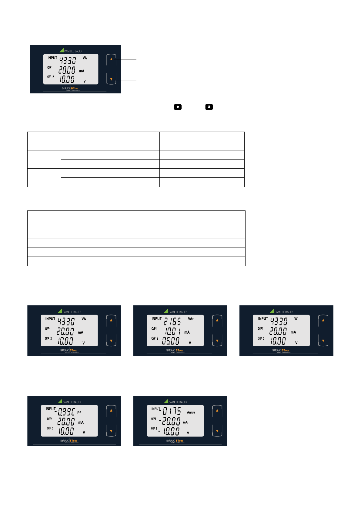
6.1 Operating the device …………………………………………………………………………………………………9
6.2 LED indication …………………………………………………………………………………………………………9
6.3 Input and output screens ………………………………………………………………………………………………9
7. Programming ………………………………………………………………………………………………………… 10
7.1 Programming via Front LCD & Two keys………………………………………………………………………………… 10
7.1.1. Password Protection …………………………………………………………………………………………… 10
7.1.1.1 Password Verification …………………………………………………………………………………… 10
7.1.1.2 Editing Existing Password ………………………………………………………………………………… 11
7.1.2 Transducer Type Selection …………………………………………………………………………………… 12
7.1.3 System Type Selection ………………………………………………………………………………………… 12
7.1.4 Output Type Selection ………………………………………………………………………………………… 12
7.1.4.1 Output 1 Type Selection ………………………………………………………………………………… 12
7.1.4.2 Output 2 Type Selection ………………………………………………………………………………… 13
7.1.5 Potential Transformer Parameter Setting ………………………………………………………………………… 13
7.1.5.1 Potential Transformer primary value ……………………………………………………………………… 13
7.1.5.2 Potential Transformer Secondary Value …………………………………………………………………… 14
7.1.6 Current Transformer Parameter Setting ………………………………………………………………………… 15
7.1.6.1 Current Transformer Primary Value………………………………………………………………………… 15
7.1.6.2 Current Transformer Secondary Value……………………………………………………………………… 16
7.1.7 Communication Parameter Setting ……………………………………………………………………………… 17
7.1.7.1 Address Setting ………………………………………………………………………………………… 17
7.1.7.2 RS 485 Baud rate ……………………………………………………………………………………… 17
7.1.7.3 RS 485 Parity Selection ………………………………………………………………………………… 18
7.1.8 Input Characteristics Setting …………………………………………………………………………………… 18
7.1.8.1 End value of Input ……………………………………………………………………………………… 18
7.1.9 Output Characteristics Setting…………………………………………………………………………………… 21
7.1.9.1 Output 1 Characteristics Setting ………………………………………………………………………… 21
7.1.9.1.1 End value of output 1 ……………………………………………………………………………… 21
7.1.9.1.2 Start value of output 1 ……………………………………………………………………………… 22
7.1.9.1.3 Elbow value of output 1……………………………………………………………………………… 23
7.1.9.2 Output 2 Characteristics Setting ………………………………………………………………………… 24
7.1.9.2.1 End value of output 2 ……………………………………………………………………………… 24
7.1.9.2.2 Start value of output 2 ……………………………………………………………………………… 24
7.1.9.2.3 Elbow value of output 2……………………………………………………………………………… 25
7.1.10 Mode Selection ……………………………………………………………………………………………… 26
8. Phasor Diagram ………………………………………………………………………………………………………… 28
9. Programming via the programming connection and the PRKAB5000 programming cable……………………………… 29
9.1. Programming via the RS485 (Modbus) interface ……………………………………………………………………… 29
9.2. DIP Switch Setting for Output ………………………………………………………………………………………… 29