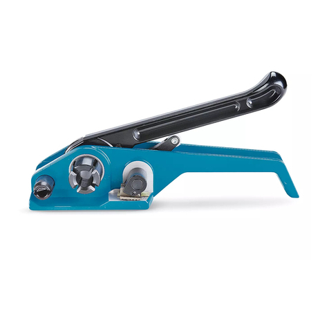
Signode GRIPPACK 114 Instruction Manual

SIGNODE !
!!
!3700 WEST LAKE AVENUE !
!!
!GLENVIEW, ILLINOIS 60026
GRIPPACK 114
BATTERY POWERED SEALER
NOTE: Fully charge battery before first use of tool.

READ THESE INSTRUCTIONS CAREFULLY.
FAILURE TO FOLLOW THESE INSTRUCTIONS CAN RESULT IN SEVERE PERSONAL INJURY.
1. STRAP BREAKAGE HAZARD
Improper operation of the tool or sharp corners on the load can result in strap breakage
during tensioning, which could result in the following:
!A sudden loss of balance causing you to fall.
!Both tool and strap flying violently towards your face.
Failure to place the strap properly around the load or an unstable or shifted load could result
in a sudden loss of strap tension during tensioning. This could result in a sudden loss of
balance causing you to fall.
Read the tool's operating instructions. If the load corners are sharp use edge protectors.
Place the strap correctly around a properly positioned load.
!Positioning yourself in-line with the strap, during tensioning and sealing, can result in
severe personal injury from flying strap or tool. When tensioning or sealing, position
yourself to one side of the strap and keep all bystanders away.
!Using strap not recommended for this sealer can result in strap breakage during sealing.
Use the correct Signode products for your application.
2. TOOL CARE
Take good care of the tool. Inspect and clean it daily, lubricate it weekly and adjust when
necessary. Replace any worn or broken parts.
3. WORK AREA
Keep work areas uncluttered and well lighted.
4. FALL HAZARD
Maintaining improper footing and/or balance when operating the tool can cause you to fall.
Do not use the tool when you are in an awkward position.
5. STRAPPING
Several types of strap can be used with this tool. Use the correct Signode products for your
application. If you need help contact your Signode Representative.
6. CUTTING TENSIONED STRAP
Use only cutters designed for cutting strap; never use claw hammers, crowbars, chisels, axes
or similar tools. Such tools will cause the strap to fly apart with hazardous force. Before
using any Signode product, read its Operation and Safety Manual.
2

READ THESE INSTRUCTIONS CAREFULLY.
FAILURE TO FOLLOW THESE INSTRUCTIONS CAN RESULT IN SEVERE PERSONAL INJURY.
7. GUARD AGAINST ELECTRIC SHOCK
8. CONSIDER WORK AREA ENVIRONMENT
!
!!
!Prevent body contact with grounded surfaces, such as pipes, radiators, ranges,
refrigerator enclosures.
!
!!
!When tool and charger are used outdoors, use only extension cords intended for
outdoors and so marked.
!
!!
!Wear protective gloves and non-skid footwear when working outdoors.
!
!!
!Do not expose power tools directly to rain.
!
!!
!Never operate tool in presence of gases or flammable liquids.
9. Never allow visitors to contact tool or extension cords. All visitors should be kept away from
work area.
10. DO NOT ABUSE TOOL
!
!!
!Keep handle dry, clean and free from oil and grease.
!
!!
!Always keep cord from heat, oil and sharp edges.
!
!!
!Always store idle tool in dry, high or locked-up place.
!
!!
!Always remove battery from tool when not in use or before servicing.
!
!!
!To avoid unintentional starting, never carry plugged-in tool with finger on switch.
11. MAINTAIN TOOL WITH CARE
Check Damaged Parts. Check for alignment of moving parts, binding of moving parts,
breakage of parts, mounting, and any other condition that may affect its operation. A guard
or other part that is damaged should be properly repaired or replaced by an authorized
service center unless otherwise indicated elsewhere in this instruction manual. Have
damaged switches replaced by authorized service center. Do not use tool if switch does not
turn it on and off.
!
!!
!When servicing double insulated tool, use identical replacement parts.
!
!!
!Keep tool clean for better and safer performance.
!
!!
!Inspect tool, battery and charger periodically and, if damaged, have repaired by
authorized service facility.
12. USE FOR THE INTENDED PURPOSE
This tool is designed for bundling round packages with Signode brand steel strapping.
POSSIBLE MISUSES
The use of any other strapping material may void this tool’s warranty.
3

TRAINING
Read the operating instructions carefully. This tool must not be used by persons not
properly trained in its use. Be certain that you receive proper training from your
employer. If you have any questions contact your Signode Representative.
EYE INJURY HAZARD
Failure to wear safety glasses with side shields can result in severe eye injury or
blindness. Always wear safety glasses with side shields which conform to ANSI
Standard Z87.1 or EN 166.
CUT HAZARD
Handling strap or sharp parts could result in cut hands or fingers. Wear protective
gloves.
SOUND PROTECTION
When operating the tool, wear ear protection.
ENVIRONMENTAL PROTECTION
Charger and batteries should be sorted for environmental-friendly recycling. Do not
open the battery. Do not throw the used battery into household waste, fire or water.
DISPOSAL
This tool is manufactured without any physical or chemical substances which could be
dangerous to health. The legal prescriptions for disposal of all the parts must be
observed. The electrical assemblies should be dismantled so that the mechanical,
electro-mechanical and electronic components can be disposed of separately.
DO NOT USE WATER
Do not use water or stream to clean the tool.
POWER SOURCE
Before starting preventive or corrective maintenance, remove the battery from the tool.
Always inspect the electrical plug and cable on charger before use. If damaged, they
must be replaced by qualified personnel.
4

TABLE OF CONTENTS Page
General Safety Instructions 2
Specifications 5
Major Components 6
Battery Charger 7
Battery Installation 8
Operating Instructions 9
Joint Formation & Inspection 10
Replacement Parts 11
Page
Troubleshooting:
Guides 15
Indicator Lights 19
Tool Maintenance 20
Maintenance Procedures 21
Declaration of Conformity 25
Signode GRIPPACK 114
Part No. 800250
STRAP SPECIFICATIONS
MODEL STRAP SEALS RECOMMENDED
TENSIONER
TYPE WIDTH THICKNESS
GRIPPACK 114 Magnus
Apex Plus
1.250"
(32mm) .025" to .031"
(.63-.80mm)
114P
114OF
GripPack
Tensioner
TOOL SPECIFICATIONS
MODEL DIMENSIONS WEIGHT
(W/ BATTERY) SOUND
PRESSURE
GRIPPACK 114 14.25" X 3.25" X 7.25"
(362mm X 83mm X 184mm) 7.5 LBS
(3.4 kg) 38 DB
5

PRODUCT IDENTIFICATION
A two letter date code can be
found on every tool. Contact
your local Signode
representative to assist in
identifying the production month
and year of the tool.
Date codes can also be used to
properly identify service parts for
this tool.
MAJOR COMPONENTS
6

BATTERY INFORMATION & CHARGING
Plug charger into your standard power outlet.
With no battery pack inserted, the charger's green
indicator light will go ON. This indicates the
charger is receiving power and the charger is ready
for operation.
When you insert the battery pack into the charger.
The charger's green indicator light will begin to
"BLINK". This indicates that the battery is receiving
a fast charge.
When the indicator light stops "BLINKING" (and
becomes a steady green light) fast charging is
complete. The battery pack is fully charged and can
be removed from the charger.
The battery pack may be used even though the
light may still be blinking. The light may require
more time to stop blinking depending on
temperature.
The purpose of the green light is to indicate that
the battery pack is fast-charging. It does not
indicate the exact point of charge. The light will
stop blinking in less time if the battery pack was
not completely charged.
When you begin the charging process of the battery pack, a steady red light could also mean the
battery pack is too hot or too cold.
Fast charging is only possible when the temperature range of the battery pack is between 32F
(0C) and 113F (45C). When needed, the internal fan of the charger will turn on to aid the charging
process and speed.
As soon as the battery pack reaches the correct temperature range, the battery charger will
automatically switch to fast charging.
If the red indicator light is "BLINKING", the battery pack cannot accept a charge.
!Check to make sure the battery pack is inserted to the charger properly.
!Clean the contacts of the charger or battery pack (e. g. by inserting and removing the
battery several times) or replace the battery pack as required.
When the battery pack is fully charged, unplug the charger (unless you're charging another
battery pack) and install the battery pack back into the tool.
7

INSTALLING A BATTERY
1. Hold the tool firmly with one hand.
2. Using your other hand, insert the battery into the
tool with a sliding motion.
3. Firmly push the battery until fully seated. When
fully seated the battery locks in place.
The Green indicator light will flash for
approximately while the tool energizes. One the
light stops flashing the tool is ready for use.
4. To remove the battery press the Red release
button on the battery and slide out.
NOTE: The power indicator light on the top of the tool will flash Green indicating the battery
has enough charge. If the indicator light flashes Red, charge the battery accordingly.
REPLACEMENT BATTERIES & CHARGERS
110 VOLT BATTERY CHARGER
P/N 800294 P/N 800293
220 VOLT BATTERY CHARGER
P/N 800386 P/N 800385
JOINT FORMATION & INSPECTION
An improperly formed joint, or a joint with an incorrect number of
notches, could result in strap separation. Before moving any package,
be certain that the joint is formed as shown in the illustration. If not,
remove the strap and check the tool for worn or broken parts. Repair
the tool before applying another strap. Failure to follow this procedure
could result in serious injury or death. If you have questions regarding
proper joint formation, contact your Signode Sales Representative.
Before making a double reverse notch seal joint, read the sealing tool’s
Operation, Parts and Safety Manual. A properly formed double reverse
notch joint will appear as shown in the illustration. Always use the correct number of seals
recommended by your Signode Sales Representative.
If the double reverse notch joint does not appear as shown in the illustration, proceed as
follows:
A. Review the tool’s operating instructions to be certain that the tool is being operated
properly before applying another strap.
B. Cut the strap off and apply a new strap and seal.
Tuck strap end back into the dispenser when not in use.
8

OPERATING INSTRUCTIONS
Wear safety glasses and gloves. Stand to one side of the strap when sealing.
Make sure all bystanders are clear before proceeding.
PLEASE NOTE: Do not operate tool without strap, as damage to the tool may occur.
1. Thread the strap from the dispenser
through a Signode 114P or 114OF seal.
Encircle the bundle and rethread the
strap end through the seal.
2. Bend the strap end backwards as shown.
Tension the strap as required. Refer to
the strap tensioner manual for the proper
use of the tool.
3. Position the sealer jaws over one end of
the seal. Press the switch located on the
handle grip. Once completed, move the
sealer jaws to the other end of the seal
and notch the seal a second time.
4. Once the second notch has been made
the seal joint can be inspected and the
strap tensioner can be removed.
9

REPLACEMENT PARTS
KEY QTY PART NO. DESCRIPTION
1 1 800234 GEAR HOUSING
21800332 RIGHT HANDLE ASSEMBLY
3 1 800333 LEFT HANDLE ASSEMBLY
4 1 800238 LEFT SIDE PLATE
5 1 800239 RIGHT SIDE PLATE
62 800266 NOTCHER
7 1 800526 WORM GEAR
81800241 ECCENTRIC PIN
9 2 800240 LINKAGE
10 1 800242 LINK PIN
11 4 800243 SEALER LINK
12 2 800245 JAW
13 2 800267 LOWER JAW PIN
14 1 800244 UPPER JAW PIN
15 1 800285 UPPER JAW PIN
16 2 800246 SPACER
17 1 800063 BEARING CAP
18 1 800236 GEAR HOUSING COVER
20 1 800527 WORM
21 1 800263 MOTOR MOUNT
24 1 800265 RUBBER BOOT
25 1 800060 TRIGGER SPRING
26 1 800268 JAW SPACER
27 1 800018 TRIGGER
28 1 800005 CONTACT PLATE
31 1 800100 PCB MOUNTING BRACKET
32 1 800286 SPACER
33 1 800522 CV SHAFT
34 1 425321 DRIVE CONNECTOR
38 1 426146 ROLLER BEARING
39 1 800311 O RING 12MM X 1.5
40 1 800309 NEEDLE BEARING 0810-RS
41 1 800310 BEARING 71906C
42 1 800312 BALL BEARING 6806
43 8 170304 M5 X 16 SHCS
44 14 280851 M4 X 12 SHCS
45 1 800059 O-RING SAE# 31 (50 DUROMETER)
46 1 800062 O-RING SAE# 26
47 2 800058 1.5 WIDE X Ø30.0 I.D. METRIC O-RING
48 8 800013 M3 X 5 SBHCS
49 3 M4 X 5 M4 X 5 SBHCS
10

KEY QTY PART NO. DESCRIPTION
50 2 800102 M2 X 10 SHCS
51 2 800049 M2 HEX JAM NUT
52 4 422835 Ø5 X 12 DOWEL PIN
53 2 280809 M5 X 35 SHCS
54 2 280819 M5 HEX LOCKNUT
55 2 010031 M5 X 25 SHCS
58 4 262456 M3 X 6 SHCS
59 4 434097 8mm EXT. RET. RING (TA# 5100-31)
60 1 293902 M4 X 5 SSS CUP
63 3 800325 SBHCS M4 X 5
64** 2 299044 SHSS M3 X 5
70 1 800309 SLEEVE BEARING
71 2 800295 12MM BALL BEARING
72 1 800254 IDLER CARRIAGE ASSEMBLY
73 12 800258 IDLER GEAR
74 3 800256 RING GEAR
75 2 800255 IDLER CARRIAGE ASSEMBLY
76 1 800260 END PLATE
77 1 800323 1.5 WIDE X Ø24.0 I.D. METRIC O-RING
78 2 800324 1.5 WIDE X Ø19.0 I.D. METRIC O-RING
79 1 800296 RETAINING RING
80 1 800375 NAMEPLATE
81 1 800376 INFORMATION SIGN
82 1 800377 INFORMATION SIGN
83 1 423953 WARNING SIGN
84 1 436387 INFORMATION SIGN
!When ordering parts please indicate tool model, part number and description.
!Recommended spare parts are underlined and should be stocked.
!Common hardware parts can be obtained at any local hardware supply.
** Use Loctite #222 (Purple) or equivalent.
11

12

13

ELECTRICAL SERVICE SUB-ASSEMBLIES
All of the service assemblies below (Keys 1 through 8) can be order together as Signode Part No. 800532.
KEY QTY PART NO. DESCRIPTION
1 1 800533 PCB The following service items include wires
2 1 800534 Contact Plate and all connectors needed for replacement.
3 1 800535 Snap Switch
4 1 800536 Snap Switch
5 1 800537 LED
6 1 800538 LED
7 1 800539 Motor
8 1 800540 Metal Sensor
14

TROUBLESHOOTING GUIDES
15

TROUBLESHOOTING GUIDES
16

TROUBLESHOOTING GUIDES
17

TROUBLESHOOTING GUIDES
18

TROUBLESHOOTING - INDICATOR LIGHTS
Charger is plugged in and receiving power.
Battery is receiving a Quick Charge.
Battery is too hot or cold to receive charge. Charging
starts when the battery reaches the proper temperature.
Battery cannot accept a charge. Replace battery.
Battery properly charged.
Operating error. Refer to tool troubleshooting.
Battery not properly charged to operate tool.
19

TOOL MAINTENANCE
GENERAL
The most common reason for poor tool performance and incorrectly formed straps joints is
improper tool maintenance. The easiest way to determine if a tool is performing correctly is by
inspecting the strap joint. Having a tool maintenance program is a simple task which consists of
three parts. First, a quick daily inspection of the tool for any worn or broken parts. Secondly,
keep each tool on a schedule of service intervals for cleaning and lubrication. Third, when
problems do occur, use the troubleshooting guide to properly determine and fix problems before
they lead to more serious tool conditions. Each of these three tasks have been outlined for this
particular tool, read and understand all information for improving the life and performance of the
tool.
TOOL INSPECTION
Visually inspect the exterior of the tool on a daily basis. Decreased tool life can be prevented by
early detection of broken parts. Replace all broken parts with new parts. Review any part
removal, replacement & adjustment instructions found in this manual.
SERVICE INTERVALS
Tool component wear is affected by the environment, strap/seal quantity and strap gauge which
the tool is subjected to. All critical moving components of the tool should be inspected
periodically. Broken parts can increase sealing effort, leading to additional component wear and
produce lower joint strength.
Inspect the components of the sealing mechanism when:
A. Joint does not appear as shown in this manual or visually it is detected that the joint
is not all formed or formed improperly.
B. Sealing effort seems sluggish or tool is difficult to remove from strap.
C. The number of cycles from one battery charge decreases.
D. When scheduled.
If there is any question that joint formation is not as shown or is suspect, it is important that you
contact your tool representative immediately.
TOOL LUBRICATION
Signode tools use a variety of greases and oils, all of which can be ordered through Signode.
When ordering indicate tool model, part number and name.
THREAD SEALANTS
Signode tools are assembled using a variety of thread sealants, all of which can be ordered
through Signode service using the appropriate description and part number.
!
!!
!Loctite #222 (Purple), Part No 422794.
20
Table of contents
Other Signode Food Saver manuals

Signode
Signode Little David LD16AE 2.0 User manual

Signode
Signode RCN-3435 Use and care manual

Signode
Signode RCNS2-34 Instruction Manual

Signode
Signode B-250 Instruction Manual

Signode
Signode RCD-1431 Instruction Manual

Signode
Signode D-58 User manual

Signode
Signode SRC Series Instruction Manual

Signode
Signode YC Series Instruction Manual

Signode
Signode D-504 Use and care manual