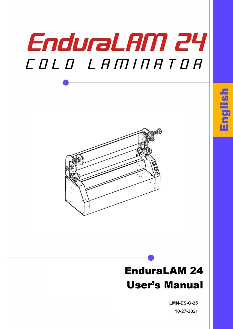
SignWarehouse EnduraLAM 3 User manual

EnduraLAM 3
User Manual
LMN-ES-C-55-1400E COLD
LMN-ES-C-55-1700E COLD
Please read this manual in detail before operation
10-27-21

1
CONTENT
Features:.......................................................................................................................................2
1. INSTALLATION...................................................................................................................3
1.1 NOTES:.................................................................................................................................3
1.2 Frame assembly ..................................................................................................................4
1.3 Machine Installation............................................................................................................5
2. Safety...............................................................................................................................8
2.1 Warning Symbols.................................................................................................................8
2.2 Safety parts .........................................................................................................................9
2.3 SAFETY NOTICE..................................................................................................................10
3. Technical parameter...................................................................................................11
4. PARTS OF LAMINATOR.....................................................................................................12
4.1Front view ..........................................................................................................................12
4.2 Back view...........................................................................................................................12
4.3 Notes.................................................................................................................................13
5. USAGE OF MACHINE.........................................................................................................18
6. Laminating process.....................................................................................................23
6.1 Lamination Principles........................................................................................................23
6.2 Operation ..........................................................................................................................23
6.3 Notes for Operation ..........................................................................................................24
7. Trouble Shooting.........................................................................................................25
8. Maintenance...................................................................................................................26
8.1 Maintenance of rollers......................................................................................................27
8.2 Cleaning..........................................................................................................................28
8.3 Checking.........................................................................................................................28
8.3.1 visual checking ....................................................................................................28
8.3.2 Safety parts checking ..........................................................................................28

2
Description:
Thank you for purchasing an EnduraLAM III laminator. In addition to the traditional
function of cold lamination, auto-peeling of liner paper and print take-up, it has the function of
increasing the laminating pressure. The function can effectively improve the output quality.
Besides, smarter and people-oriented innovation in the design concept and details will give you
simple and relaxing lamination experience.
Please read the manual carefully, including the installation, operation and maintenance to
ensure the best output and the service life of the machine. For after sale service, please fill in
the Warranty Card in the manual and fax or mail it to our company.
Features:
Simple Control Panel
Unlimited Speed control
Hand Crank Pressure Adjustment
Removable Working Table
Roll to Roll Lamination
Hands-free Foot Pedal
Emergency Stop button
Supported Applications:
Cold Laminating of digitally printed films, mounting of pressure-sensitive adhesive films to
rigid substrates, transfer tape application.

3
1. INSTALLATION
1.1 NOTES:
1. Before unpacking, carefully check for signs of apparent shipping damage. If there is any
indication that the product has been damaged, note it on the bill of lading and contact
SIGNWarehouse Product Support or Customer Service at your earliest opportunity.
2. After unpacking, check the contents against the packing list to make sure everything has
been shipped as expected.
3. The area of intended use for the laminator should be spacious enough for personnel to
move around the unit, and free of dust, corrosive fumes, and flammable or combustible
substances. For best results use the equipment in a climate-controlled environment.
4. After installation, adjust each of the casters to ensure that the product is secure and
level. The casters are designed to support the laminator for moving short distances.
NOTE: Take care when installing and moving the laminator. The equipment is heavy and may
require two or more adults to place, position or move the laminator.

4
1.2 Stand assembly
1) Unpack all the parts for the floor stand and make sure there are no missing pieces.
2) Assemble the two legs and all shafts according to FIG 1 below.
3) Install the casters to the left and right legs(Where two casters with brakes and two without
brakes are supplied, make sure you install one of each kind on each end of the stand.).
FIG 1) 1. Cross-bar 2. legs 3. Rolling casters. 4. Hex socket(M8*16)5. Hex socket(M8*16)

5
1.3 Machine Installation
1) Carefully unwrap and remove the laminator from crate. This will require at least two
able-bodied adults. Use 4 of the supplied M10 screws to mount the laminator to the floor stand.
Take care to position the laminator facing the same direction as the front of the cross-bar, as seen
below (FIG2).
NOTE: When installing and moving the laminator, hold it by the frame. Do not use the hand
crank or friction wheel. These may provide an insecure hand-hold and may result in injury or
damage to the equipment.
fixed by M10

6
2)Working Table Installation(Refer to Pic)。
1. Hold the media feed table sideways and
place it onto the front of the laminator. Align
the media table opening and screw.
2. Under the feed table(A), at each end, push
the table interlocks towards the side frames to
secure the feed table.
3. Replace the pressure plate.
3)Shaft assembly(Refer to 4.3)。
4)The hand crank on the right front of machine is
used to adjust the roller pressure. Turn the
handle counter-clockwise to lower the main
roller, or to increase the roller pressure. The
Gap/Pressure crank must be installed before
first use. Remove the shaft cap, fix the hand
wheel onto the axle, and then re-install the
shaft cap.
5)Remove the red shipping locks on both ends of roller ( See below).
6)Connect the foot pedal and wiring as following illustration.
3
1
2
A

7
Power: Cables and On/Off Switch
A: Power switch
B: Power cable
C: Foot Pedal connector
7)Turn on the machine, roller is rotating. Make trial laminating if everything is well and check the
lamination result.
A
C
B

8
2 Safety
Read the safety instructions and familiarize yourself with the main structure, performance and
operation measures before starting the machine. When using the equipment, please take note of
the warning labels placed on the surface. These are provided to support safe operation of the
product. All personnel operating the laminator should read this manual and become familiar with
the warning labels and their meaning.
2.1 Warning Labels
A. Crush Hazard: Placing hands or fingers in or near rollers during operation may pose hazard
of injury to hands. Keep hands away from rollers during operation.
B. Chain hazard: Keep hands, hair, and loose clothing away from drive chains and gears.
A
B
C
D
E
F

9
Hands, hair, or clothing caught in chains or gears may pose risk of injury.
C. Crush Hazard: Placing hands or fingers in or near rollers during operation may pose hazard
of injury to hands. Keep hands away from rollers during operation.
D. Electric shock:Risk of electric shock. Do not touch these components unless the unit is
powered down and unplugged.
E. EMERGENCY STOP:In case of emergency, press the red button to immediately cease
operation.
2.2 Safety Features
◼Emergency
In case of emergency, press the large, red
Emergency Stop button to shut off the power
and stop the rollers. To resume operation and
release the Estop, turn the button clockwise. It
will rise to its normal position automatically.
Press “on” from control panel to resume
movement of the pressure roller.
NOTE:In case of emergency, press the
Emergency Stop button immediately !
EMERGENCY SWITCH
◼Safety Sensor
There is a ssafety sensor located in front of
roller and support shaft. When an object
blocks the sensor, the machine detects the
risk of injury and immediately stops the
pressure roller. To resume operation, turn
on the switch on the control panel. To ensure
safe operation, it is recommended that you
test the safety sensor before first use of the
product.
NOTE: Use of the foot pedal deactivates the safety sensor.

10
2.3 SAFETY NOTICE
All operators should read this manual before using the product.
The power supply should match the power requirements on the nameplate and
specifications. Use a grounded three-plug power cable. Do not change the ground wiring.
In the event that maintenance or repair of the product requires the side panels to
be removed, be sure to turn off the main power and unplug the laminator to avoid
risk of electric shock or other physical damage or injury.
The facility should be well ventilated. Keep the machine away from water, excessive
moisture, or flammable, or combustible liquids or vapors.
To prevent accidental damage to product or injury do not leave tools on the media feed
table or any other surface of the laminator.
To prevent risk of short circuits or corrosion do not clean with water. Use a soft, dry, lint-free
cloth to remove dust and other contaminants.
Clean the roller by periodically activating it to expose the entire cylinder. Cleaning at only
one point may result in buildup of debris and potential damage to the roller.
Inspect the power cables and foot switch connector cables regularly to prevent risk of shock.

11
3 EnduraLAM Specifications
specification
EnduraLAM 55
EnduraLAM 65
Maximum media width
55 inches
63 inches
maximum laminating speed
19.6 feet/min
19.6 feet/min
Roller Diameter
4072 inches (120mm)
Roller Maximum Height
1.38 inches (35mm)
Roller Lifting method
Manual, hand crank
Voltage
220V/110C AC 50Hz
Power
Laminator: 120W, Motor: 90 - 120W
Dimensions
(Length, width, height)
72.5 x 24 x 49 in
(1840 x 610 x
1250mm)
80 x 24 x 49 in
(2040 x 610 x 1250mm)
Weight
385 lbs. (175 kg)
485 lbs. (220 kg)
Length
Height
Width

12
4PARTS OF LAMINATOR
4.1Front view
1.Caster 2. Bracket 3. Shaft 4.left cabinet 5.Emergency Stop 6.Working table 7. Media guide rod
8.Roller
9.Liner take up 10. Control panel 11.Right cabinet 12.Hand crank 13.Foot pedal
4.2 Back view
1
2
3
4
5
6
7
8
9
10
11
12
13
4
1
2
3
5

13
1.connection 2. Media take up 3.Film unwind 4.Friction wheel 5.Electric parts cabinet
4.3 Notes
◼Foot Pedal
The Foot pedal is another way to control the
motion of the rollers. This is a convenient
option for working with large-format media. In
some instances, your hands will be busy
loading media. The foot pedal allows you to
start the rollers. Pressure on the foot pedal
starts the rollers. Lifting off the pedal stops the
rollers.
Roll feed direction is still actuated by the
button on the control panel.
NOTE: The protect sensor can’t be used with foot pedal together. Please be careful when
placing media with the foot pedal to prevent getting your hands caught in the rollers.
◼Media Feed table and Media Guide Rod
The media feed table and media guide rod are
used to put tension on media. Both are
moveable. Take off the media feed table when
loading or unloading media or when cleaning
the roller. Take off media guide rod when
preparing to laminate media, put it back when
media is loaded and you’re ready to laminate.
➢Removing Media Feed Table :
1. Press the button to open the plug.
2. Hold the middle and lift.
B
A
1
2&3

14
3. Grasp the media feed table near the
middle and pull outwards.
➢Assemble the front turntable:
1. Hold the middle part of working table, put
down slowly.
2. Put down while the gap against screw.
3. Lock the plug.
➢Media guide rod:
Lift and take off the media guide rod. Insert
screw in the holes of media guide rod to
reinstall.
◼Top and Bottom Roller
The top and bottom rollers are the key
component of the laminator and they directly
affect the quality of laminating. Both top and
bottom rollers are silicon-coated to prevent
accidental adhesion by media. The bottom
1
2
3

15
roller is controlled by drive motors, manual
crank and speed control switch. The top roller is
operated by friction against the bottom roller.
NOTE: Keep hands away from pressure rollers during operation. In case of
accidental entanglement, press the Emergency Stop button.
◼Idler bar
The idler bar is used to keep the film as smooth
as possible while it winds around and through
the rollers.
◼Unwind/rewind shafts
There are four shafts for this machine: They are…
•Film liner rewinder (A)
a
b
c
d
A
D
B
C

16
•Film unwind shaft (B)
•Media rewinder (C)
•Media unwind shaft (D)
The four shafts are interchangeable. The film liner rewinder and media rewinder are
actuated by the drive motors. The film unwind shaft and media unwind shaft are not.
Remove the pin from saddles, then move out one side of shaft. For assembly, left side first,
the driven end of each shaft is slotted to engage a key. Three rubber strip on the shaft to hold
the media core.
The friction wheel is A,B,C D. Rotate clock-wise rotating to increase the friction, rotate
counter-clockwise to decrease the friction. Use the friction wheel to adjust the speed and
manage consistency.
◼CASTERS
Total four casters for this machine. Two of
casters (A)can be locked to prevent movement,
two casters(B) without brakes.
◼Pressure limit
This device limits the space of pressure plate.
In order to protect speed controller, the hand
crank cannot be used when the maximum
A
Stop nut
B
A
B
2
3
1

17
roller pressure has been achieved.
NOTE: It is a default position ,Do not adjust
◼Drive system
⚫Film unwind drive liner take up through
the sprocket wheel. The running speed is
different because the number of teeth of
the two sprockets is different, you can
adjust the two brake tension knob to
change the speed ratio.
⚫Motor drive roller and media take up
through the sprocket wheel.
◼Control Panel
➢Cold series:
A- velocity control knob:Control the speed of
the roller。
换Direction Switching Button
B- Direction Switching Button:Control the
rotation direction of the roller。
C- Motor on/off:Start or stop the motor。
C
B
A

18
5 USAGE OF MACHINE
◼Power Connection
⚫Power cable: Use the supplied 120V Power Cord to connect the machine to a 110/120 Volt
20-amp receptacle.
⚫Main switch: It is installed in the rear of machine (Cold series is the rocker switch) the switch
has two positions, up to open, down to close.
◼Foot pedal
The Foot pedal is another way to control the motion of the rollers. This is a convenient
option for working with large-format media. In some instances, your hands will be busy
loading media. The foot pedal allows you to start the rollers. Pressure on the foot pedal
starts the rollers. Lifting off the pedal stops the rollers.
Roll feed direction is still actuated by the button on the control panel.
NOTE: The protect sensor can’t be used with foot pedal together. Please be careful when
placing media with the foot pedal to prevent getting your hands caught in the rollers.
◼Emergency button
In case of emergency, press the large, red Emergency Stop button to shut off the power and
stop the rollers. To resume operation and release the Estop, turn the button clockwise. It will
rise to its normal position automatically. Press “on” from control panel to resume movement
of the pressure roller.
NOTE:In case of emergency, press the Emergency Stop button immediately !
◼OPERATION OF ROLLER
Open the handle on the manual crank (See illustration below). Use the handle to rotate the
wheel clockwise to raise the roller, and counter-clockwise to lower the roller. The pressure
controlled by operator based on different material and specification.

19
NOTE: Remove the hand crank before flipping upward.
◼Function shaft Installation and using
Three rubber straps on each shaft are designed
to create friction against the inside of the media
core. Slide the 3” core on the shaft, then rotate it
to tighten the core on the shaft.
◼Friction pad checking and replacement
The friction pad is a consumable and will need to be replaced regularly. Check it quarterly for
signs of wear.
Friction System For Media Unwind: it is comprised of the bracket, metal friction pad, fiber
friction pad, spring, spring bracket and black handle. Adjust pressure on spring by rotating the
handle. When the shaft is rotating, the key connects fiber friction pad and bracket to create
friction, which is generated by the friction pad. Over time, the friction pad will wear out and need
to be replaced. When friction diminishes to the point where the media unwind function is
impaired, inspect and replace the friction pad.
How to replace: Remove the handle, spring, fiber friction pad, and metal friction pad. Then install
a new metal friction pad.
⚫Friction System For Media Rewind: The Friction Media Rewind system consists of the
bracket, metal friction pad, fiber friction pad, spring, spring bracket and black handle. Adjust
pressure on the spring by rotating the handle. When the shaft rotates, the key connects the
fiber friction pad and bracket to create friction. The rewind shaft is motor controlled. The
Rewind sprocket driven by friction rotation. When the shaft rotates, the key connects fiber
friction pad and bracket to create friction. The friction pad for media rewind is also a
consumable that will need to be replaced over time. When friction diminishes to the point
where the media rewind function is impaired, inspect and replace the friction pad.
⚫Friction System For Film Unwind: The Friction Film Unwind system consists of the bracket,
metal friction pad, fiber friction pad, spring, spring bracket and black handle. Adjust
pressure on the spring by rotating the handle. When the shaft rotates, the key connects
This manual suits for next models
2
Table of contents
Other SignWarehouse Laminator manuals
