SILENT KNIGHT IDP-Photo Manual

IDP-Photo, IDP-Photo-T and
IDP-Acclimate Intelligent
Photoelectric Smoke Sensors
Installation and Maintenance
Instructions
SPECIFICATIONS
Operating Voltage Range: 15 to 32 VDC
Standby Current: 300µA @ 24 VDCMax.
Alarm Current (LED on): 6.5 mA @ 24 VDC
Operating Humidity Range: 10% to 93% Relative
Humidity, non condensing
Operating Temperature Range: 0° to 49°C (32° to 120°F);
IDP-Photo 0° to 38°C
(32° to 100°F); IDP-
Photo-T, IDP-Acclimate
Height: 2.0 inches (51mm)
installed in SS-B6 Base
Diameter: 6.1 inches (155 mm)
installed in SS-B6 Base
4.1 inches (104 mm)
installed in B501 Base
Weight: 5.2 oz. (147 g)
This sensor must be installed in compliance with the
control panel system installation manual. The installation
must meet the requirements of the Authority Having
Jurisdiction (AHJ). Sensors offer maximum performance
when installed in compliance with the National Fire
Protection Association (NFPA); see NFPA 72.
GENERAL DESCRIPTION
Models IDP-Photo, IDP-Photo-T and IDP-Acclimate
are plug-in type smoke sensors that combine a
photoelectronic sensing chamber with addressable-
analog communications. The sensors transmit an analog
representation of smoke density over a communication
line to a control panel. Rotary decade switches are
provided for setting the sensor’s address.
Two LEDs on the sensor are controlled by the panel
to indicate sensor status. An output is provided for
connection to an optional remote LED annunciator (P/N
RA400Z). Models IDP-Acclimate and IDP-Photo-T
combines a photoelectronic sensing chamber and 135°F
(57.2°C) fixed temperature heat detector.
Please refer to the operation manual for the UL listed
control unit for specific operation of the IDP-Photo, IDP-
Photo-T and IDP-Acclimate.
The IDP-Photo, IDP-Photo-T and IDP-Acclimate require
compatible addressable communications to function
properly. Connect these sensors to listed-compatible
control panels only.
SPACING
Silent Knight recommends spacing sensors in compliance
with NFPA 72. In low air flow applications with smooth
ceilings, space sensors 30 feet apart. For specific information
regarding sensor spacing, placement, and special
applications, refer to NFPA 72.
Duct Applications: IDP-Photo and IDP-Photo-T are listed
for use in ducts.
NOTE: These products are not listed for use inside duct
smoke detectors.
WIRING GUIDE
All wiring must be installed in compliance with the
National Electrical Code, applicable local codes, and any
special requirements of the Authority Having Jurisdiction.
Proper wire gauges should be used. The installation
wires should be color-coded to limit wiring mistakes and
ease system troubleshooting. Improper connections will
prevent a system from responding properly in the event
of a fire.
Remove power from the communication line before
installing sensors.
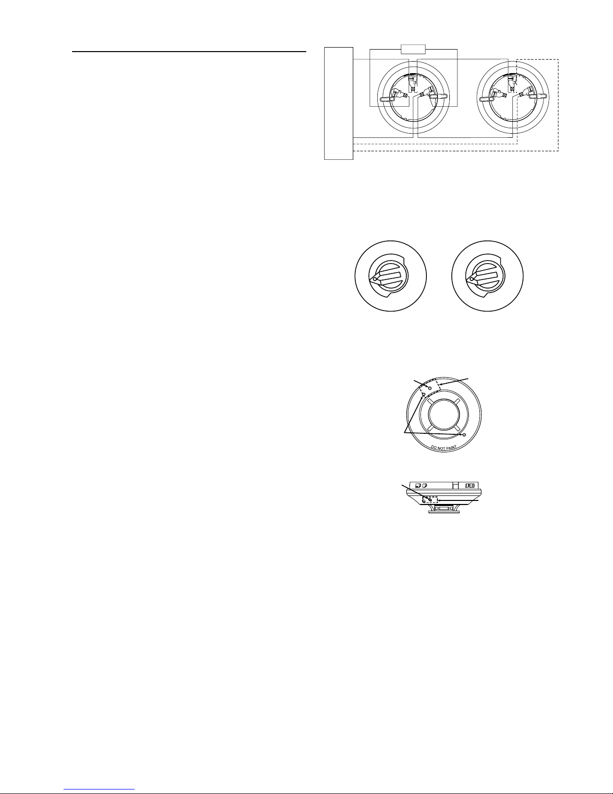
1. Wire the sensor base (supplied separately) per the
wiring diagram, see Figure 1.
2. Set the desired address on the sensor address switches,
see Figure 2.
3. Install the sensor into the sensor base. Push the sensor into
the base while turning it clockwise to secure it in place.
4. After all sensors have been installed, apply power to
the control unit and activate the communication line.
5. Test the sensor(s) as described in the TESTING
section of this manual.
Dust covers provide limited protection against airborne
dust particles during shipping. Dust covers must be
removed before the sensors can sense smoke. Remove
sensors prior to heavy remodeling or construction.
TAMPER-RESISTANCE
Models IDP-Photo, IDP-Photo-T and IDP-Acclimate
include a tamper-resistant capability that prevents their
removal from the bracket without the use of a tool. Refer to
the base manual for details on making use of this capability.
K200-04-00 1 I56-2720-00R
CAUTION
TESTING
Before testing, notify the proper authorities that the system
is undergoing maintenance, and will temporarily be out of
service. Disable the system to prevent unwanted alarms.
All sensors must be tested after installation and periodically
thereafter. Testing methods must satisfy the Authority
Having Jurisdiction (AHJ). Sensors offer maximum
performance when tested and maintained in compliance
with NFPA 72.
The sensor can be tested in the following ways:
A. Functional: Magnet Test (P/N M02-04-01 or M02-09-00)
This sensor can be functionally tested with a test
magnet. The test magnet electronically simulates
smoke in the sensing chamber, testing the sensor
electronics and connections to the control panel.
1. Hold the test magnet in the magnet test area as
shown in Figure 3.
2. The sensor should alarm the panel.
Two LEDs on the sensor are controlled by the panel
to indicate sensor status. Coded signals, transmitted
from the panel, can cause the LEDs to blink, latch
on, or latch off. Refer to the control panel technical
documentation for sensor LED status operation and
expected delay to alarm.
B. Smoke Entry: Aerosol Generator (Gemini 501 or
other UL lised devices)
The GEMINI model 501 aerosol generator can be
used for smoke entry testing. Other UL listed smoke
generating devices may be used as well. Set the
generator to represent 4%/ft to 5%/ft obscuration as
described in the GEMINI 501 manual. Using the bowl
shaped applicator, apply aerosol until the panel alarms.
For IDP-Acclimate, smoke entry testing should be
performed immediately following the magnet test.
Magnet test initiates an approximately 10 minute period
when the detector’s signal processing software routines
are not active. Failure to first perform the magnet test
will introduce a time delay before the detector alarms.
C. Direct Heat Method (Hair dryer of 1000-1500
watts). IDP-Photo-T and IDP-Acclimate only.
A hair dryer of 1000-1500 watts should be used to
test the thermistors. Direct the heat toward either
of the two thermistors, holding the heat source
approximately 12 inches from the detector in order to
avoid damaging the plastic housing. The detector will
reset only after it has had sufficient time to cool. Make
sure both thermistors are tested individually.
A sensor that fails any of these tests should be cleaned as
described under CLEANING, and retested. If the sensor fails
after cleaning, it must be replaced and returned for repair.
When testing is complete, restore the system to normal
operation and notify the proper authorities that the system
is back in operation.
Figure 1. Wiring Diagram
Figure 2. Rotary Address Switches
Caution: Do Not Loop Wire Under Terminal 1 or 2.
Break Wire Run To Provide Supervision of Connections.
Figure 3.
LED Status
Indicators
Magnet T est
Marker
Tes t Magnet
Position
Tes t Magnet
Position
Magnet T est
Marker
C0100-00
C0146-00
C0145-00
TENS ONES
9
8
7
6
5
4
3
210
9
8
7
6
5
4
3
210
32
1
32
1
+
–
–
+
OPTIONAL RETURN LOOP
REMOTE ANNUNCIATOR
+ –
UL LISTED COMPATIBLE
CONTROL PANEL
K200-04-00 2 I56-2720-00R
CLEANING
Before removing the detector, notify the proper
authorities that the smoke detector system is undergoing
maintenance and will be temporarily out of service.
Disable the zone or system undergoing maintenance to
prevent unwanted alarms.
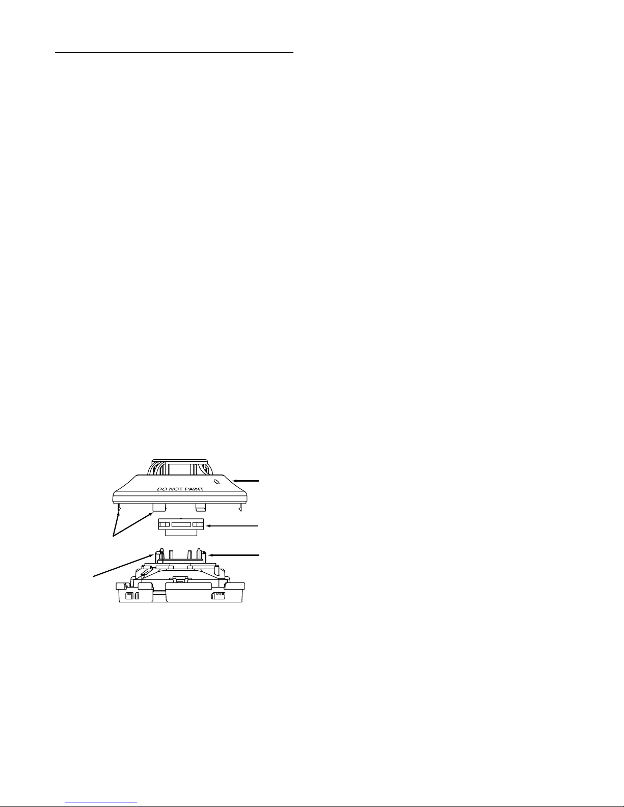
1. Remove the sensor to be cleaned from the system.
2. Remove the sensor cover by pressing firmly on each
of the four removal tabs that hold the
cover in place.
3. Vacuum the screen carefully without removing it. If
further cleaning is required continue with
Step 4, otherwise skip to Step 7.
4. Remove the chamber cover/screen assembly by
pulling it straight out.
5. Use a vacuum cleaner or compressed air to remove
dust and debris from the sensing chamber.
6. Reinstall the chamber cover/screen assembly by
sliding the edge over the sensing chamber. Turn until
it is firmly in place.
7. Replace the cover using the LEDs to align the
cover and then gently pushing it until it locks into
place. Make sure that the thermistors do not become
bent under the cover on the IDP-Photo-T and IDP-
Acclimate models.
8. Reinstall the detector.
9. Test the detector as described in TESTING.
10. Reconnect disabled circuits.
11. Notify the proper authorities that the system is back
on line.
Sensor
Cover
Sensing
Chamber
Cover and
Screen
Cover
Removal
Tabs Sensing
Chamber
Optional
Thermistors
(IDP-Photo-T and
IDP-Acclimate)
IDP-Photo-T and IDP-Acclimate
K200-04-00 3 I56-2720-00R
C0803-00

FCC Statement
This device complies with part 15 of the FCC Rules. Operation is subject to the following two conditions: (1) This device may not cause harmful
interference, and (2) this device must accept any interference received, including interference that may cause undesired operation.
Note: This equipment has been tested and found to comply with the limits for a Class B digital device, pursuant to Part 15 of the FCC Rules. These limits
are designed to provide reasonable protection against harmful interference in a residential installation. This equipment generates, uses and can radiate
radio frequency energy and, if not installed and used in accordance with the instructions, may cause harmful interference to radio communications.
However, there is no guarantee that interference will not occur in a particular installation. If this equipment does cause harmful interference to radio
or television reception, which can be determined by turning the equipment off and on, the user is encouraged to try to correct the interference by one
or more of the following measures:
– Reorient or relocate the receiving antenna.
– Increase the separation between the equipment and receiver.
– Connect the equipment into an outlet on a circuit different from that to which the receiver is connected.
– Consult the dealer or an experienced radio/TV technician for help.
Please refer to insert for the Limitations of Fire Alarm Systems
K200-04-00 4 I56-2720-00R
7550 Meridian Circle
Maple Grove, MN 55369-4927
763-493-6455; 800-328-0103
Fax: 763-493-6475
http://www.silentknight.com
© 2005 Silent Knight 12/04
This manual suits for next models
2
Popular Accessories manuals by other brands


INNOBIZ
INNOBIZ Elia Instructions for use

Karpo
Karpo Prolaser 896 5-DOT user manual

Snom
Snom M200 SC Administrator and provisioning manual

fontastic
fontastic Kari 10 user manual

Huawei
Huawei BTS3900 V100R003 Hardware description

ATC Electrical & Mechanical
ATC Electrical & Mechanical atc.ie HANDSU Installation and operation manual


