SILENT KNIGHT 5204 User manual

Fire Control/Communicator
Part Number 150644D, 6/01
MODEL 5204
Installation and
Operation Manual

150644 i
Content
Section 1
Introduction .............................................................................................................................................. 1-1
1.1 How to Use This Manual ......................................................................................................................... 1-1
1.2 Optional Accessories ................................................................................................................................ 1-2
Section 2
Specifications and System Planning ..................................................................... 2-1
2.1 Electrical Specifications ........................................................................................................................... 2-1
2.2 Environmental Specifications .................................................................................................................. 2-1
2.3 Wiring Specifications ............................................................................................................................... 2-2
Section 3
Agency Listings, Approvals, and Requirements ................................... 3-1
3.1 Federal Communications Commission (FCC) ......................................................................................... 3-1
3.1.1 FCC Warning .................................................................................................................................... 3-1
3.2 Underwriters Laboratories (UL) .............................................................................................................. 3-2
3.2.1 Requirements for All Installations .................................................................................................... 3-2
3.2.2 Requirements for Central Station Fire Alarm Systems .................................................................... 3-2
3.2.3 Requirements for Local Protected Fire Alarm Systems ...................................................................3-3
3.2.4 Requirements for Auxiliary Protected Fire Alarm Systems for Fire Alarm Service ........................ 3-3
3.2.5 Requirements for Remote Station Protected Fire Alarm Systems - Polarity Reversal ..................... 3-3
3.3 California Fire Marshal (CFM) ................................................................................................................ 3-4
3.4 Factory Mutual (FM) ............................................................................................................................... 3-4
3.5 Materials & Equipment Board of Acceptance (MEA) .............................................................................3-4
Section 4
Installation Overview ................................................................................................................... 4-1
4.1 Model 5204 Wiring Diagram ................................................................................................................... 4-1
4.2 Current Draw Worksheet ......................................................................................................................... 4-2
4.2.1 Worksheet Example .......................................................................................................................... 4-3
4.2.2 Worksheet Requirements .................................................................................................................. 4-4
Section 5
Control Panel Installation ...................................................................................................... 5-1
5.1 Grounding the Model 5204 Cover ...........................................................................................................5-2
5.2 Smoke Power Selection ........................................................................................................................... 5-2
5.3 Power Supply Wiring ............................................................................................................................... 5-2
5.4 Battery Connection .................................................................................................................................. 5-3

Model 5204 Fire Control/Communicator Installation Manual
ii 150644
5.5 Mounting the 5204 ................................................................................................................................... 5-3
5.6 Terminal Strip Description ....................................................................................................................... 5-3
5.7 Model 5205 Dialer and Telephone Line Connection (Optional) ............................................................. 5-5
Installation .............................................................................................................................. 5-5
Ring Detect Circuit ................................................................................................................5-6
5.8 Cable Connectors .....................................................................................................................................5-7
Status (P1) .............................................................................................................................. 5-7
Model 5230 (P2) .................................................................................................................... 5-7
Power Supply (AC) Connector (P4) ...................................................................................... 5-7
Section 6
Compatible Product Installation ................................................................................... 6-1
6.1 Zone Wiring ............................................................................................................................................. 6-1
6.1.1 Four-Wire Smoke Detector Connection ........................................................................................... 6-2
6.1.2 Two-Wire Smoke Detector Connection ........................................................................................... 6-3
Notes for Both Tables ............................................................................................................ 6-3
6.2 Connections to Compatible Silent Knight Products ................................................................................ 6-6
6.2.1 Model 4180 Status Display Module ................................................................................................. 6-6
6.2.2 Model 5220 Direct Connect Module ................................................................................................ 6-7
6.2.2.1 Installation .............................................................................................................................. 6-8
6.2.2.2 City Box Connect (24 VDC Systems Only) .......................................................................... 6-8
6.2.2.3 NFPA 72 Polarity Reversal (12 or 24 VDC Systems) ........................................................... 6-9
6.2.3 Model 5230 Remote Annunciator .....................................................................................................6-9
6.2.3.1 Setting ID Codes .................................................................................................................... 6-9
6.2.3.2 Wiring the 5230 Remote Annunciator ................................................................................. 6-10
6.2.3.3 Mounting the 5230 Remote Annunciator .............................................................................6-11
6.2.4 Model 5395 Distibuted Power Module ........................................................................................... 6-11
6.2.5 Model 7181 Zone Converter ........................................................................................................... 6-12
6.3 Supervised Notification Device Outputs ................................................................................................ 6-13
6.4 Auxiliary Relays .................................................................................................................................... 6-20
6.5 External Silence Keyswitch (Optional) .................................................................................................. 6-21
Section 7
Normal Operation ............................................................................................................................. 7-1
7.1 Built-in Touchpad and Model 5230 Annunciator Operation ................................................................... 7-2
7.1.1 Operating Modes ............................................................................................................................... 7-5
7.1.2 Built-in Touchpad Display Codes ..................................................................................................... 7-5
7.1.3 Silencing the System ......................................................................................................................... 7-7
7.1.4 LED Indicators .................................................................................................................................. 7-7
7.2 System Testing ......................................................................................................................................... 7-8
7.2.1 Fire Drills (Mode 20) ........................................................................................................................ 7-8
7.2.2 Walk Test (Mode 22) ........................................................................................................................ 7-8
7.2.3 Automatic Self Test .......................................................................................................................... 7-8
7.2.4 Watchdog Circuit .............................................................................................................................. 7-8
7.3 Zone Characteristics ................................................................................................................................. 7-9
7.3.1 Zone Type ......................................................................................................................................... 7-9
7.3.2 Cross Alarm .................................................................................................................................... 7-10
Example ............................................................................................................................... 7-10
7.3.3 Pre-Alarm ........................................................................................................................................ 7-11
7.3.4 Smoke Verification ......................................................................................................................... 7-12
7.3.5 Zone Response Time ...................................................................................................................... 7-13

Content
150644 iii
Section 8
Programming ......................................................................................................................................... 8-1
8.1 EEPROM Information ............................................................................................................................. 8-1
8.2 Downloading ............................................................................................................................................ 8-2
8.3 How to Use Step Programming ............................................................................................................... 8-2
8.3.1 Entering Step Programming (Mode 27) ............................................................................................ 8-3
8.3.2 Programming Options ....................................................................................................................... 8-3
8.3.3 Advancing to the Next Option .......................................................................................................... 8-4
8.3.4 Going to a Specific Step ................................................................................................................... 8-4
8.3.5 Viewing Previously Programmed Data ............................................................................................ 8-5
8.3.6 Correcting Errors .............................................................................................................................. 8-5
8.3.7 Entering Hexadecimal Digits ............................................................................................................ 8-5
8.3.8 Programming Examples .................................................................................................................... 8-6
Example 1: Choosing a Programming Option from a Menu ................................................ 8-6
Example 2: Programming Location Description Names ...................................................... 8-6
8.3.9 Exiting Step Programming ................................................................................................................ 8-7
8.4 Step Programming Options ...................................................................................................................... 8-8
8.4.1 Programming Steps ........................................................................................................................... 8-8
Section 9
Troubleshooting ................................................................................................................................9-1
9.1 Silencing Notification Devices ................................................................................................................9-1
9.2 Earth Ground Fault Troubleshooting ....................................................................................................... 9-1
9.2.1 P3 and P4 Fault ................................................................................................................................. 9-1
9.2.2 Accu-Zone‚ Troubleshooting (Mode 25) ..........................................................................................9-2
Special Notes .......................................................................................................................... 9-3
9.3 Troubleshooting and System Messages ................................................................................................... 9-4
Section 10
Central Station Reporting ................................................................................................... 10-1
10.1 Power Loss Reporting ............................................................................................................................ 10-1
10.2 Reporting Formats .................................................................................................................................. 10-1
10.2.1 SIA Format Printed Messages ........................................................................................................ 10-2
10.2.2 Silent Knight 3/1 and Sescoa 3/1 Formats ...................................................................................... 10-3
10.2.3 Silent Knight FSK and 4+2 Formats ............................................................................................... 10-4
10.2.4 Radionics BFSK Format ................................................................................................................. 10-5
Appendix A
Programming Quick Reference .................................................................................... A-1

Model 5204 Fire Control/Communicator Installation Manual
iv 150644

150644 1-1
Section 1
Introduction
The Model 5204 is a low-cost fire alarm control panel with optional communicator that meets
UL 864 and NFPA 72 requirements. It is available with a 12 or 24 VDC power supply, which
you can select in the field. The 5204 cabinet can be surface mounted or flush mounted.
1.1 How to Use This Manual
The Model 5204 Fire Control/Communicator Installation Manual (P/N 150644) is intended
for those people involved with the installation, maintenance, and programming of the 5204
panel. It covers wiring, connection to compatible products, normal operation, programming,
troubleshooting, and central station reporting.
This manual is a comprehensive guide. It provides detailed instructions and can be used for
reference. The installation manual is organized chronologically by the tasks that need to be
performed to get the panel operating according to your needs. You can skip sections that do
not apply to your installation.
In this manual, the following conventions are used:
ENTER or
Represents a key that you press on a touchpad.
Shaded displays represent messages that you see on the built-in
touchpad (7-segment) light emitting diode (LED) display.
SMOKE RESET TIME Words typed in this font represent messages that you see on a liquid
crystal display (LCD).
ENTER

Model 5204 Fire Control/Communicator Installation Manual
1-2 150644
1.2 Optional Accessories
The following Silent Knight components can be used with the Model 5204 panel.
Table A-1: Compatible Components (Manufactured by Silent Knight)
Model What it Does
2608 Ground Start Relay Used for ground start phone lines(not UL listed).
4180 Status Display Module For remote annunciation of alarm and trouble status information for
each zone.
5220 Direct Connect Module For direct alarming and trouble transmission from the 5204 to a
supervising station.
5230 Remote Annunciator Provides complete system control. Includes touchpad (keypad) with
membrane keyswitches, back-lit LCD indication of zone and system
status, and built-in speaker for audible annunciation. Used for
programming with English-language prompts.
Quick connect program cable,
part number 130294 For temporarily connecting the 5230 to the 5204 for programming.
5293 Distributed Power
Module For connecting more notification devices than the 5204 normally
allows.
5541 Downloading Software For remote programming of the 5204.
5530 Modem Modem for downloading; required if using the 5541 software.
5205 Dialer Module Enables the 5204 to function as a communicator panel.
7181 Zone Converter Converts a zone from class B (style B) to class A (style D) or from class
A to class B. One 7181 per zone to be converted.

150644 2-1
Section 2
Specifications and System Planning
2.1 Electrical Specifications
2.2 Environmental Specifications
It is important to protect the 5204 control panel from water. To prevent water damage, the
following conditions should be AVOIDED when mounting the units:
• Do not mount directly on exterior walls, especially masonry walls (condensation)
• Do not mount directly on exterior walls below grade (condensation)
• Protect from plumbing leaks
• Protect from splash caused by sprinkler system inspection ports
• Do not mount in areas with humidity-generating equipment (such as dryers, production
machinery)
When selecting a location to mount the 5204 control panel, the unit should be mounted where
it will NOT be exposed to temperatures outside the range of 0° C-49° C (32° F-120° F) or
humidity outside the range of 10%-85% at 30° C (86° F) noncondensing.
See also the mounting recommendations in Section 5.5.
Circuit 12-Volt Panel 24-Volt Panel
Primary AC 120 Vrms at 60 Hz, 2500 mA rms 120 Vrms at 60 Hz, 2500 mA rms
Total External DC Load 3.0A 3.0A
Accessory Power 9.5 V to 13.8 V max., 1500 mA 19.7 V to 27.6 V max., 1500 mA
+12 V Accessory Power 8.0 V to 14.0 V, 175 mA 11.5 V to 14.0 V, 175 mA
Bell Power 9.3 V to 13.8 V max., 1500 mA 19.8 V to 27.6 V max., 1500 mA
Smoke Power 9.3 V to 13.8V max., 1000 mA 19.7 V. to 27.6 V. max., 1000 mA
Battery Charging Voltage 13.5 to 13.8 V 27.0 V - 27.6 V
Minimum Low Battery Detect 10.2 V 20.4 V
Minimum Low AC Detect 100 Vrms at 60 Hz, full load 100 Vrms at 60 Hz, full load
Minimum Class B Trouble Detect 1.5 mA 2.4 mA
Maximum Class B Alarm Detect 11.7 mA 12.1 mA
Maximum Watchdog Response Time 50 sec. 50 sec.
Note: When running at full load, it is normal for the main heatsink to be hot.

Model 5204 Fire Control/Communicator Installation Manual
2-2 150644
2.3 Wiring Specifications
To avoid induced noise (transfer of electrical energy from one wire to another), keep input
wiring isolated from high current output and power wiring. Induced noise can interfere with
telephone communication or even cause false alarms. Avoid pulling one multiconductor
cable for the entire panel. Instead, separate the wiring as follows:
DO NOT pull wires from different groups through the same conduit. If you must run them
together, do so for as short a distance as possible or use shielded cable. Connect the shield to
circuit ground at the panel. You must route high and low voltages separately.
For the same reasons, you should route the wiring within the cabinet around the perimeter of
the cabinet. It should not cross the printed circuit board where it could induce noise into the
sensitive microelectronics or pick up unwanted RF noise from the high speed circuits.
High frequency noise, such as that produced by the inductive reactance of a speaker or bell,
can also be reduced by running the wire through ferrite shield beads or by wrapping it around
a ferrite toroid. See Figure 2-1.
Figure 2-1 Wiring Identification
High current input/output: AC power, speaker, and notification device wiring
Low current input/output: Annunciator and zone loop wiring
Audio input/output: Telephone wiring

150644 3-1
Section 3
Agency Listings, Approvals, and Requirements
3.1 Federal Communications Commission (FCC)
1. If requested by the telephone company, the following information must be provided
before the 5204 can be connected to the phone lines:
2. This device may not be directly connected to coin telephone or party line services.
3. This device cannot be adjusted or repaired in the field. In case of trouble with the device,
notify the installing company or return to:
Silent Knight Security Systems
7550 Meridian Circle
Maple Grove, MN 55369-4927
612-493-6455
800-328-0103
4. If the 5204 or 5205 dialer causes harm to the telephone network, the telephone company
will notify the user in advance that temporary discontinuance of service may be required.
If advance notice is not practical, the telephone company will notify the user as soon as
possible. Users have the right to file complaints, if necessary, with the Federal Communi-
cations Commission.
5. The telephone company may make changes in its facilities, equipment, operations, or pro-
cedures that could affect the operation of the equipment. If this happens, the telephone
company will provide advance notice to allow you to make the necessary modifications to
maintain uninterrupted service.
3.1.1 FCC Warning
A Manufacturer: Silent Knight Security Systems
B Model Number: 5204
C FCC registration number AC6USA-73710-AL-E
Ringer equivalence: 0.9B
D Type of jack (to be installed by the
telephone company RJ31X
Warning
This device has been verified to comply with FCC Rules Part 15. Operation is subject to the following conditions:
(1) This device may not cause radio interference, and (2) This device must accept any interference received,
including interference that may cause undesired operation.

Model 5204 Fire Control/Communicator Installation Manual
3-2 150644
3.2 Underwriters Laboratories (UL)
The 5204 is UL listed as a control unit for use in NFPA 72 systems. If the 5204 and its
accessories are to be used as part of a UL installation, carefully read the UL requirements in
this section. For more information on the following NFPA 72 standards, refer to the NFPA
National Fire Alarm Code, 1993 Edition.
• Chapter 3
Local Protected Fire Alarm Systems
• Chapter 4
Central Station Fire Alarm Systems
Auxiliary Protected Fire Alarm Systems for Fire Alarm Service (City Box)
Remote Station Protected Fire Alarm Systems (Polarity Reversal)
3.2.1 Requirements for All Installations
General requirements are described below. When installing an individual device, refer to the
specific section of the manual for additional requirements. See also the subsection below that
describes special requirements for the type of installation (for example, Central Station Fire
Alarm systems, Local Protected Fire Alarm systems, and so on).
1. All AC wiring to and from the 5204 cabinet must be enclosed in conduit.
2. Total 24-hour standby current must not exceed 875 mA in 12V mode or 438 mA in 24V
mode. Total 60-hour standby current must not exceed 350 mA in 12V mode or 175 mA in
24V mode.
3. All electrical connections must comply with the ratings shown in Section 5.6.
4. Because the 5204 panel itself is the main source of alarm and trouble annunciation, you
must select a location for the panel that allows alarms and troubles, including pre-alarms,
to be heard by end-users responsible for maintaining the panel.
3.2.2 Requirements for Central Station Fire Alarm
Systems
1. You must program a phone number and a test time (See Section 8, Step 69 and Step 76) so
that the 5204 sends an automatic daily test to the central station.
2. In systems using class A (style D) zones (converted using the Model 7181 Zone Con-
verter), do not use more than 5 waterflow devices. (See Section 6.2.5.)
3. Auxiliary relays may NOT be programmed to activate for Pre-Alarm. (See Section 8,
Step 20.)

Agency Listings, Approvals, and Requirements
150644 3-3
3.2.3 Requirements for Local Protected Fire Alarm
Systems
At least one UL listed supervised audible appliance must be used.
3.2.4 Requirements for Auxiliary Protected Fire Alarm
Systems for Fire Alarm Service
1. Do not exceed the current load restrictions shown in Section 4.
2. The Model 5220 Direct Connect module must be installed (see Section 6.2.2 for wiring).
3.2.5 Requirements for Remote Station Protected Fire
Alarm Systems - Polarity Reversal
1. Do not exceed the current load restrictions shown in Section 4.
2. The Model 5220 Direct Connect module must be installed (see Section 6.2.2 for wiring).

Model 5204 Fire Control/Communicator Installation Manual
3-4 150644
3.3 California Fire Marshal (CFM)
The CFM approval number for the 5204 is 7165-0559:117
3.4 Factory Mutual (FM)
The 5204 is FM approved under project # OW6A3.AY when used in conjunction with the
Silent Knight Model 9000 Receiver.
3.5 Materials & Equipment Board of Acceptance
(MEA)
The 5204 is now approved under MEA. Previously, approval was given from the City of New
York Board of Standards and Appeals (BSA). The 5204 is now approved under MEA Number
429-92-E.

150644 4-1
Section 4
Installation Overview
4.1 Model 5204 Wiring Diagram
Figure 4-1 is a wiring diagram for wiring the various components of the Model 5204 panel.
Any device connected to terminal 24 must be UL listed for fire use, and must be rated at
12 V/24 V. Terminals 22 and 26 are the only terminals that should be used to return smoke
power and should not be used for any other purpose.
Figure 4-1 Model 5204 Wiring Diagram

Model 5204 Fire Control/Communicator Installation Manual
4-2 150644
4.2 Current Draw Worksheet
* This information must be used with Table 4-1 and Table 4-2 to complete battery calculations.
Device Number of
Devices Current per Device Standby
Current Alarm Current
For each device, use this formula:This column X This column = Current per number of devices
5204 Fire Control/
Communicator 1Standby: 120 mA mA
Alarm: 400 mA mA
4180 Status Display module (2 max.) Standby: 20 mA mA
Alarm: 140 mA mA
5205 Dialer 1 Standby : 10 mA mA
Alarm: 100 mA mA
5220 Direct Connect module 1 Standby: 50 mA mA
Alarm: 50 mA mA
5230 Remote Annunciator (3 max.) Standby: 60 mA mA
Alarm: 120 mA mA
7181 Zone Converter (4 max.) Standby 12V/24V: 52/35 mA mA
Alarm 12V/24V: 90/65 mA mA
ACurrent Subtotals: mA mA
Smoke Detectors Refer to device manual for current ratings. See Tables 6-2 and 6-3 for max. # per loop.
Standby: mA mA
Alarm: mA mA
Standby: mA mA
Alarm: mA mA
Standby: mA mA
Alarm: mA mA
BCurrent Subtotals: mA mA
Notification Devices Refer to device manual for number of devices and current ratings.
Alarm: mA mA
Alarm: mA mA
CCurrent Subtotals: mA mA
Additional Devices
Standby: mA mA
Alarm: mA mA
Standby: mA mA
Alarm: mA mA
Standby: mA mA
Alarm: mA mA
Standby: mA mA
Alarm: mA mA
DCurrent Subtotals: mA mA
Total current ratings of all devices in system (add A through D)*: mA mA
ETotal current ratings converted to amperes (x .001): A A

Installation Overview
150644 4-3
4.2.1 Worksheet Example
A worksheet is included to help you calculate the amount of current the system draws on
standby (idle) and in active (trouble or alarm) conditions. Refer to Table 4-2 to see the
different battery sizes available and the maximum standby current load each can support.
Figure 4-2 illustrates how to complete the worksheet:
Figure 4-2 Current Draw Worksheet Example
Maximum current draw for signaling devices - 1.5 A
(See Section 6.3 for additional information on signaling outputs.)
Maximum Loop resistance for smoke detectors - 30 ohms
To measure maximum loop resistance, connect an ohmmeter across the leads of a discon-
nected loop.
(See Table 6-2 and Table 6-3 for maximum number of smoke detectors per loop.)

Model 5204 Fire Control/Communicator Installation Manual
4-4 150644
4.2.2 Worksheet Requirements
The following steps must be taken when determining 5204 current ratings:
1. For the Model 5204, you must measure the alarm (active) current. If only one current rat-
ing is listed, the draw for that device is the same whether the system is in alarm or standby
condition. The exception is for notification devices, which are rated at alarm current only.
Standby current for sounding devices is 0 mA.
2. To measure the maximum alarm current of the panel, measure the current draw (with no
devices connected to the panel) by connecting a DC amp meter in series with one of the
batteries. Disconnect the AC power source. Put the panel in alarm. The meter will indi-
cate the alarm current, which will be in the range of 120-400 mA. Fill in the system alarm
current in the Current per Device column on the Current Draw worksheet. You can esti-
mate without measuring the alarm current by filling in the maximum total alarm current of
400 mA.
Note: In a 12-volt system, measure the current from both batteries (disconnect both grounds).
3. For smoke detectors, notification devices and devices not mentioned in the manual, refer
to the device manual for the current ratings. The worksheet example shown on the previ-
ous page provides rough estimates for a “worst case” installation.
4. Use Table 4-1 to determine the battery amp hour rating needed for your installation. Refer
to the example (Figure 4-3) that follows. Note that the calculated rating in Row H cannot
exceed the ratings shown in Table 4-2).
*Use next size battery with capacity greater than required.
Table 4-1: Battery Calculations
Total Standby Current Total Alarm Current
ATotal supervisory current from the Current Draw worksheet
(row E). A
BNumber of standby hours (24 and 60 for NFPA 72, Chapter
1, 1-5.2.5). H
CMultiply Lines A and B. AH
DTotal alarm current from the Current Draw worksheet (row
E). A
EAlarm sounding period in hours.
(For example, 5 minutes = .084 hours.) H
FMultiply lines D and E. AH
GAdd lines C and F. AH
HMultiply line G by 1.2.
(Total ampere/hours required*) AH

Installation Overview
150644 4-5
Figure 4-3 Battery Calculation Example
5. Refer to Table 4-2 to verify the battery size you need to provide at least the total standby
current you have calculated. If the installation must meet requirements for NFPA 72
(Auxiliary Protected Fire Alarm Systems for Fire Alarm Service or Remote Station Pro-
tected Fire Alarm Systems - Polarity Reversal), the total standby current cannot exceed the
amount shown in the last column of the following table:
* Required for NFPA 72 Auxiliary Protected Fire Alarm systems for Fire Alarm Service (City Box) and Remote
Station Protected Fire Alarm systems (Polarity Reversal).
Warning!
Silent Knight does not support the use of batteries smaller than those listed in Table
4-2. If you use a battery too small for your installation, the system can overload it
and you may have less than the required 24 hours standby power. Use Table 4-1 to
calculate the correct battery amperes/hour rating needed for your installation.
Table 4-2: Maximum Battery Standby Load
Rechargeable
Battery Size Max. Load for 24 hrs. Standby,
5 mins. Alarm *Max. Load for 60 hrs. Standby,
5 mins. Alarm
17 Amp Hours 438 mA 175 mA
34 AH (if wired in parallel) 875 mA 350 mA

Model 5204 Fire Control/Communicator Installation Manual
4-6 150644
The following formula was used to calculate the figures in Table 4-2:
I = [AH ÷ H] x 0.70
6. Ensure that the total alarm current you calculated, including current for the panel itself,
does not exceed 3.5 A. This is the maximum alarm current allowable, whether the panel
provides 12 V or 24 V of smoke power.
Where: I = Standby current
AH = Ampere-hour rating of battery
H = Standby hours
0.70 = A constant used to de-rate the battery to assure a 5-year life.

150644 5-1
Section 5
Control Panel Installation
The major components of the Model 5204 PC board are described in this section. Figure 5-1
shows the 5204 (fuseless) printed circuit board.
Figure 5-1 Model 5204 Board Assembly
Other manuals for 5204
1
Table of contents
Other SILENT KNIGHT Control Panel manuals

SILENT KNIGHT
SILENT KNIGHT INTELLIKNIGHT 5808 User manual
SILENT KNIGHT
SILENT KNIGHT IFP-1000 Technical specifications

SILENT KNIGHT
SILENT KNIGHT IFP-1000 Technical specifications

SILENT KNIGHT
SILENT KNIGHT SK-2224 User manual

SILENT KNIGHT
SILENT KNIGHT 5207 User manual

SILENT KNIGHT
SILENT KNIGHT 5207 Manual
SILENT KNIGHT
SILENT KNIGHT 5700 Technical specifications

SILENT KNIGHT
SILENT KNIGHT INTELLIKNIGHT 5808 User manual
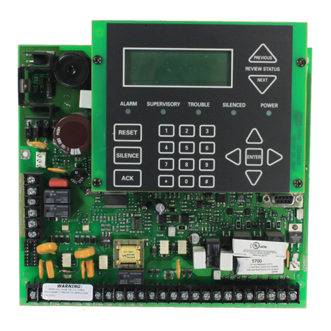
SILENT KNIGHT
SILENT KNIGHT 5700 User manual


