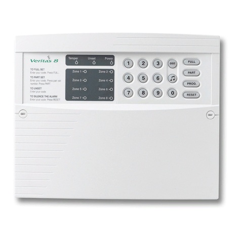
SILENT KNIGHT SK-2224 User manual

Fire Control Panel
Part Number 151051F, 02/02
SK-2224
Installation and
Operation Manual

151165 i
Content
Section 1
Overview ..........................................................................................................................................................1
1.1 SK-2224 Description ................................................................................................................................ 1-1
1.2 How to Contact Silent Knight .................................................................................................................. 1-1
Section 2
Agency Requirements ...................................................................................................................1
2.1 FCC Warning ........................................................................................................................................... 2-1
2.2 Underwriters Laboratories (UL) .............................................................................................................. 2-1
2.2.1 Requirements for All Installations ................................................................................................ 2-1
2.2.2 Requirements for Protected Premises (Local) Fire Alarm Systems .............................................. 2-1
Section 3
Before You Begin Installing ...................................................................................................1
3.1 What’s in the Box? ................................................................................................................................... 3-1
3.2 Optional Accessories ................................................................................................................................ 3-2
3.3 SK-2224 Board Layout ........................................................................................................................... 3-3
3.4 Electrical Specifications ........................................................................................................................... 3-4
3.5 Environmental Specifications .................................................................................................................. 3-4
3.6 Mounting the SK-2224 ............................................................................................................................. 3-5
3.7 Assembly .................................................................................................................................................. 3-6
3.8 Wiring Specifications ............................................................................................................................... 3-7
3.9 Calculating Current Draw and Standby Battery ...................................................................................... 3-8
3.9.1 Worksheet Requirements .............................................................................................................. 3-8
Filling in the Current Draw Worksheet, Table 3-6 (Section 3.9.3) ............................................... 3-8
3.9.2 Maximum Battery Standby Load .................................................................................................. 3-8
3.9.3 Current Draw Worksheet .............................................................................................................. 3-9
Section 4
Hardware Installation ......................................................................................................................1
4.1 AC Power ................................................................................................................................................. 4-1
4.2 Battery Connection ..................................................................................................................................4-2
4.3 Initiating Circuit Installation .................................................................................................................... 4-3
4.3.1 Contact Wiring .............................................................................................................................. 4-3
4.3.2 Two-Wire Smoke Detector Wiring ............................................................................................... 4-3
4.3.3 Four-Wire Smoke Detector Wiring ............................................................................................... 4-4
4.3.4 Notification Appliance Circuit Installation ................................................................................... 4-5
4.4 Alarm and Trouble Relays ....................................................................................................................... 4-5
4.5 Auxiliary Power Circuit ........................................................................................................................... 4-5
4.6 Door Release Wiring ................................................................................................................................ 4-6

Model SK-2224 Fire Alarm Control Panel Installation/Operation Manual
ii 151165
4.7 Optional Accessories Installation ............................................................................................................. 4-7
4.7.1 Installing the Serial Driver Board (Model SK-2884) .................................................................... 4-7
Wiring the SK-2884 to an Expansion Device ............................................................................... 4-8
4.7.2 SK-2866 LED Annunciator Installation ........................................................................................ 4-8
SK-2866 Electrical Specification .................................................................................................. 4-8
Wiring the SK-2866 to the SK-2884 ............................................................................................. 4-8
Setting the SK-2866’s address .................................................................................................... 4-10
Mounting the SK-2866 ................................................................................................................ 4-10
4.7.3 SK-2880 Installation ................................................................................................................... 4-11
SK-2880 Specifications ............................................................................................................... 4-11
4.7.3.1 Connecting the SK-2880 to the SK-2884 ............................................................................ 4-12
4.7.3.2 Setting the SK-2880 Address ............................................................................................... 4-12
4.7.3.3 Open Collector Outputs (P1, P2, and P3) ............................................................................ 4-13
Wiring SK-2880 Open Collector Outputs ................................................................................... 4-14
4.7.3.4 SK-2880 Input Switches and Relay Wiring ......................................................................... 4-15
4.7.3.5 Mounting the SK-2880 ......................................................................................................... 4-16
Section 5
System Configuration ....................................................................................................................1
Section 6
System Operation ................................................................................................................................1
6.1 Meaning of LEDs ..................................................................................................................................... 6-1
6.2 Operation Keys (Switches) ...................................................................................................................... 6-3
Appendix A
Compatible Devices ..........................................................................................................................1
A.1 Smoke Detectors ..................................................................................................................................... A-1
A.1.1 Enhanced Mode ............................................................................................................................ A-1
A.1.2 Two-Wire Smoke Detectors ......................................................................................................... A-2
A.1.3 Four-Wire Smoke Detectors ......................................................................................................... A-7
A.2 Notification Appliances .......................................................................................................................... A-8

151165 1-1
Section 1
Overview
1.1 SK-2224 Description
The Model SK-2224 is a two zone, 24-volt fire alarm control panel having the following
features:
• Two Class B zones
• Two notification circuits rated at 2.5 amps total.
• 2.5 amp power supply
• Dedicated alarm and trouble relays
• Auxiliary power output (.5 amp max.) for powering special applications, such as door
holders.
• Enhanced Verification Mode, a built-in feature that distinguishes two-wire smoke detec-
tors from pull stations.
• Housed in a 12-13/16"W x 15-1/8"H x 3-3/8"D metal cabinet
• Cabinet supports two 7.0 AH standby batteries
1.2 How to Contact Silent Knight
If you have a question or encounter a problem not covered in this manual, contact Silent
Knight Technical Support at 800-328-0103 (or 612-493-6455). To order parts, contact Silent
Knight Sales at 800-446-6444 (or 612-493-6435).

Model SK-2224 Fire Alarm Control Panel Installation/Operation Manual
1-2 151165

151165 2-1
Section 2
Agency Requirements
2.1 FCC Warning
This device has been verified to comply with FCC Rules Part 15. Operation is subject to the
two following conditions: (1) This device may not cause radio interference, and (2) This
device must accept any interference received, including interference that may cause undesired
operation.
2.2 Underwriters Laboratories (UL)
The SK-2224 is UL Listed as a control unit for use in NFPA 72 systems. If the SK-2224 and
its accessories are to be used as part of a UL installation, carefully read the UL requirements
in this section. For more information on NFPA 72 standards, refer to the NFPA National Fire
Alarm Code.
2.2.1 Requirements for All Installations
General requirements are described in this section. When installing an individual device,
refer to the specific section of the manual for additional requirements.
1. All field wiring must be installed in accordance with NFPA 70 National Electric Code.
2. Use UL listed smoke detectors and notification appliances compatible with the SK-2224
from those specified in the Appendix to this manual.
3. If you are using the smoke verification feature:
• Do not use smoke detectors with built-in alarm verification.
• Select "Enhanced Mode" if the installation includes pull stations or water flow
switches.
4. A full system checkout must be performed any time the panel is programmed.
5. UL installations require use of Model 7628 EOL resistor assembly.
2.2.2 Requirements for Protected Premises (Local) Fire
Alarm Systems
At least one UL listed supervised notification appliance must be used.

Model SK-2224 Fire Alarm Control Panel Installation/Operation Manual
2-2 151165

151165 3-1
Section 3
Before You Begin Installing
3.1 What’s in the Box?
The Model SK-2224 ships with the following hardware:
Note: See Section 3.7 for assembly instructions.
Table 3-1: Contents of Shipping Box
Main Part Containing Model
Number
Part Quantity/Item
1 Cabinet 122509
Panel Bag 1 Control Board 202224
1 Installation/
Operation Manual 151051
Hardware Bag
2 #8 Screws 119152
2 #8 Nuts 119538
3 Self-tapping Screws 119296
1 Earth Ground Wire 140668
1 Battery Wire Harness 130420
1 battery Jumper 140694
1 Transformer
120 Vrms @ 60Hz 115061
or a
230 Vrms at 50Hz 115031
1 Viewing Bezel 122508
4 End-of-line Resistors 111682

Model SK-2224 Fire Alarm Control Panel Installation/Operation Manual
3-2 151165
3.2 Optional Accessories
Table 3-2 is a list of optional accessories that can be used with the Model SK-2224 Fire Alarm
Control Panel.
* Requires a SK-2884 to operate with the SK-2224 control panel.
Table 3-2: Option Accessories for the SK-2224
Model
Number Name Description
SK-2884 Serial Driver Board Used to interface all SK-2224 expansion devices to the SK-
2224 panel. Supports 1 DACT (Model SK-2104) and any
combination of 4 LED Annunciators (Model SK-2866) or I/O
Modules (Model SK-2880).
*SK-2880 Input/Output (I/O) Module Used to drive customized annunciators and interface devices.
*SK-2866 LED Annunciator Remote LED annunciator with Silence and Reset keyswitch
inputs.
Model 7628 UL listed End-of-line
(EOL) Resistor. EOL resistor required for UL installations.

Before You Begin Installing
151165 3-3
3.3 SK-2224 Board Layout
Figure 3-1 shows the SK-2224 circuit board, including locations of terminals, connectors, DIP
switches, and LEDs.
Figure 3-1 Model SK-2224 Layout
Zone 2 Notification
Appliance
Circuits
Trouble &
Alarm Relays Auxiliary
Power
Output
Backup
Battery
Connector
AC Power
Connector
Annunciator
Programming
DIP Switches
On-Board
Piezo Sounder
SK-2884
Serial
Interface
Connector
Inputs

Model SK-2224 Fire Alarm Control Panel Installation/Operation Manual
3-4 151165
3.4 Electrical Specifications
Note: * When ordering, specify your voltage requirements.
3.5 Environmental Specifications
It is important to protect the SK-2224 control panel from water. To prevent water damage, the
following conditions should be AVOIDED when mounting the units:
• Do not mount directly on exterior walls, especially masonry walls (condensation)
• Do not mount directly on exterior walls below grade (condensation)
• Protect from plumbing leaks
• Protect from splash caused by sprinkler system inspection ports
• Do not mount in areas with humidity-generating equipment (such as dryers, production
machinery)
Table 3-3: Electrical Specifications
Circuit Rating
Primary AC *120 Vrms at 60 Hz, or 230 Vrms at 50 Hz
Total External DC Load 2.5A @ 24 VDC
+24V Auxiliary Power 19.8 V to 28.0 V, 0.5 A max.
Trouble & Alarm Relays 2.5 A @ 30 VDC resistive
Notification Appliance Power 19.8 V to 28.0 V, 2.5 A max.
Smoke Detector Power 19.8 V to 28.0 V, 1.0 A max.
Battery Charging Voltage 27.0 - 27.6 V
Maximum Battery Charging Current 750 mA
Minimum Low Battery Detect 20.4 V
Minimum Low AC Detect 100 Vrms at 60 Hz, full load
Table 3-4: Environmental Specifications
Storage Temperature: -4° - 167° F (-20 - 75° C)
Operating Temperature: 32° - 120° F (0° - 49° C)
Humidity: 10 - 85% non-condensing

Before You Begin Installing
151165 3-5
3.6 Mounting the SK-2224
Read the environmental specifications in Section 3.5 before mounting the cabinet.
The panel should be accessible to main drop wiring runs. It should be mounted as close to the
center of the building as possible and located within a secured area, but should be accessible
for testing and service. End-users responsible for maintaining the panel should be able to hear
alarms and troubles. When selecting a location, keep in mind that the panel itself is the main
source of alarm and trouble annunciation.
Mount the cabinet so it is firmly secured to the wall surface. When mounting the cabinet on
concrete, especially when moisture is expected, attach a piece of 3/4-inch plywood to the
concrete surface and then attach the cabinet to the plywood. Also mount any other modules to
the plywood.
Follow these steps to mount the control panel cabinet:
1. Place the cabinet on the mounting surface, level the cabinet and mark the top two
mounting holes.
2. Screw the top two mount screws about 3/4 of the way into the mounting surface.
3. Hang the control panel cabinet on the top mounting screws through the top mounting
screw keyholes.
Figure 3-2 Cabinet Mounting Holes
4. Insert the bottom two mounting screws into the cabinet’s bottom mounting holes.
5. Tighten all four mounting screws until the cabinet is properly secured.
6. Insert all cabinet components. See Section 3.7.
Top Mounting
Screw Keyholes
Bottom
Mounting Holes
15”
11”
12-1/2”

Model SK-2224 Fire Alarm Control Panel Installation/Operation Manual
3-6 151165
3.7 Assembly
The components listed in Table 3-1 are all packed within the cabinet and require some
assembly. Follow these steps to assemble the components inside the cabinet:
1. Remove keys from the envelope taped to the top of the cabinet.
2. Unlock the cabinet door.
3. Remove the packing material and the SK-2224 components.
4. Snap the bezel into the opening in the front of the cabinet. See Figure 3-3.
Note: The bezel will fit in only one way.
Figure 3-3 The SK-2224 Assembly Diagram
5. With the two #8 screws and the two #8 nuts (with built in washers), mount the transformer
in the holes in the upper left hand corner of the cabinet. See Figure 3-3.
6. With the three self-tapping screws mount the control board on the cabinet stand-offs.
Note: See Section 4 for transformer connections and battery connections.
Important! The electronic components on the control panel are sensitive to electrostatic discharge
(static electricity). Wear a grounding strap when handling the control board.
Side View of
Slotted Stand-Off
Bezel Insertion
Transformer
Installation
CPU Mounting
Screws

Before You Begin Installing
151165 3-7
3.8 Wiring Specifications
Induced noise (transfer of electrical energy from one wire to another) can cause false alarms
or interfere with control panel operation in other ways.
To avoid induced noise, follow these guidelines:
• Isolate input wiring from high current output and power wiring. Do not pull one multicon-
ductor cable for the entire panel. Instead, separate the wiring as follows:
High current input/output: AC power, speaker, and notification appliance wiring
Low current input/output: Annunciator and initiating circuit wiring
Audio input/output: Telephone wiring
• Do not pull wires from different groups through the same conduit. If you must run them
together, do so for as short a distance as possible or use shielded cable. Connect the shield
to circuit ground at the panel. You must route high and low voltages separately.
• Route the wiring within the cabinet around the perimeter of the cabinet. It should not cross
the printed circuit board where it could induce noise into the sensitive microelectronics or
pick up unwanted RF noise from the high speed circuits. See Figure 3-4 for an example.
• High frequency noise, such as that produced by the inductive reactance of a speaker or
bell, can also be reduced by running the wire through ferrite shield beads or by wrapping it
around a ferrite toroid.
Figure 3-4 Wire Routing Example
Important! Do not run 120 VAC line voltage in fire alarm raceways.

Model SK-2224 Fire Alarm Control Panel Installation/Operation Manual
3-8 151165
3.9 Calculating Current Draw and Standby Battery
This section is for helping you determine the current draw and standby battery needs for your
installation.
3.9.1 Worksheet Requirements
The following steps must be taken when determining SK-2224 current draw and standby
battery requirements.
Filling in the Current Draw Worksheet, Table 3-6 (Section 3.9.3)
1. For the SK-2224, the worst case current draw is listed for the panel and is recorded in the
table at Line A.
2. Add up the current draw for all smoke detectors and record in the table at Line B.
3. Add up all notification appliance loads and record in the table at Line C.
4. Any additional devices should be recorded at Line D.
5. Make sure that the alarm current without the panel (Lines B-D) does not exceed 2.5 A.
The total alarm current (including the panel, Lines A-D) should not exceed 2.75 A.
6. Complete the remaining instructions in Table 3-6 for determining battery size require-
ments.
3.9.2 Maximum Battery Standby Load
Table 3-5 shows the maximum battery standby load for the SK-2224 based on 24 and 60 hours
of standby. The standby load calculations of line D in the Current Draw Calculation
Worksheet (Table 3-6) must be less than the number shown in Table 3-5 for the battery size
used and standby hours required.
Note: Batteries greater than 7 AH must be installed in a enclosure UL listed .
Table 3-5: Maximum Battery Standby Load
Rechargeable Battery Size Max. Load for 24 hrs.
Standby, 5 mins. Alarm Max. Load for 60 hrs.
Standby, 5 mins. Alarm
7 AH 270 mA 110 mA
12 AH 425 mA 170 mA

Before You Begin Installing
151165 3-9
3.9.3 Current Draw Worksheet
Use this worksheet to determine current requirements during alarm/battery standby operation.
(Copy this page if additional space is required.)
*Note:If you are using door holders, you do not need to consider door holder current for alarm current because
power is removed during that time. However, during normal operation, door holders draw current and
must be included in the total standby current that can be drawn from the panel.
Note: Total standby current must not exceed maximum Battery standby load listed in Table 3-5.
Table 3-6: Current Draw Calculations
Device Number of
Devices Current per Device Standby
Current Alarm
Current
For each device, use this formula: This Column X This column = Current per number of devices
SK-2224 Panel 1 Standby: 50 mA 50 mA
Alarm: 250 mA 250 mA
A Current Subtotals: 50 mA 250 mA
Smoke Detectors Refer to device manual for current ratings. See Appendix to this manual for
max. # per circuit.
Standby: mA mA
Alarm: mA mA
Standby: mA mA
Alarm: mA mA
Standby: mA mA
Alarm: mA mA
B Current Subtotals (100mA Max. Alarm Current): mA mA
Notification Devices Refer to device manual for number of devices and current ratings.
Standby: mA mA
Alarm: mA mA
Standby: mA mA
Alarm: mA mA
C Current Subtotals: mA mA
Accessory Devices
SK-2884 Standby: 10 mA mA
Alarm: 10 mA mA
SK-2865 Standby: 35 mA mA
Alarm: 75 mA mA
SK-2880 Standby: 35 mA mA
Alarm: 175 mA mA
SK-2104 Standby: 33 mA mA
Alarm: 70 mA (while dialing) mA
D Current Subtotals: mA mA
*Additional Devices
Standby: mA mA
Alarm: mA mA
Standby: mA mA
Alarm: mA mA
E Current Subtotals: mA mA
FTotal current rating of all devices in system (add TOTALS OF A-E) X .001: A A
GNumber of standby hours. (24 or 60 for NFPA 72, chapter 1, 1-5.2.5): H
HMultiply lines F (standby current) and G: Total standby AH AH
IAlarm sounding period in hours. (For example, 5 minutes = .0833 hours) H
JMultiply lines F (alarm current) and I: Total alarm AH AH
KAdd lines H and J. (AH = Ampere Hours) Total AH required AH

Model SK-2224 Fire Alarm Control Panel Installation/Operation Manual
3-10 151165

151165 4-1
Section 4
Hardware Installation
4.1 AC Power
At installation, connect the transformer AC inputs to the AC power source as shown in Figure
4-1. It may be necessary for a professional electrician to make this connection.
The AC inputs are rated as 120 VAC, 60 Hz or 230 VAC, 50 Hz. See Table 3-1 for more
information.
Figure 4-1 AC Power Connection
To AC
Power
White
Black
Green
Yellow
Control Panel
Transformer
Earth Ground

Model SK-2224 Fire Alarm Control Panel Installation/Operation Manual
4-2 151165
4.2 Battery Connection
The SK-2224 battery charge capacity is 7.0 AH. Use two 12V batteries of the same AH rating.
Determine the correct AH rating as per your current load calculation (see Table 3-6).
Wire batteries in series to produce a 24-volt equivalent. Do not parallel batteries to increase
the AH rating.
Note: The SK-2224 cabinet supports two 7.0 AH batteries.
Figure 4-2 Battery Connection
Battery jumper (P/N140694)
shipped with the control panel.

Hardware Installation
151165 4-3
4.3 Initiating Circuit Installation
4.3.1 Contact Wiring
Wire normally open contacts as shown in Figure 4-3. This is the type of wiring that would
typically be used for manual stations, heat detectors and other normally open devices.
Figure 4-3 N.O. Contact Wiring
4.3.2 Two-Wire Smoke Detector Wiring
Figure 4-4 shows how to connect two-wire smoke detectors to the SK-2224 initiating circuits.
The figure uses Silent Knight’s SLK-24F with HSB-224 base as an example. You can use any
detector that has been UL listed for compatibility with the SK-2224. Refer to the Appendix for
a list of compatible devices. Refer to Section 5 for configuration options.
Figure 4-4 Two-Wire Smoke Detector Wiring
Table of contents
Other SILENT KNIGHT Control Panel manuals

SILENT KNIGHT
SILENT KNIGHT 5207 Manual

SILENT KNIGHT
SILENT KNIGHT IFP-1000 Technical specifications

SILENT KNIGHT
SILENT KNIGHT INTELLIKNIGHT 5808 User manual
SILENT KNIGHT
SILENT KNIGHT 5700 User manual

SILENT KNIGHT
SILENT KNIGHT IFP-1000 Technical specifications
SILENT KNIGHT
SILENT KNIGHT 5204 User manual
SILENT KNIGHT
SILENT KNIGHT 5700 Technical specifications

SILENT KNIGHT
SILENT KNIGHT INTELLIKNIGHT 5808 User manual

SILENT KNIGHT
SILENT KNIGHT 5207 User manual

