SILENT KNIGHT SD505-DUCT User manual
II. MOUNTING THE DETECTOR
The sampling tubes may be ordered to a desired length or
ordered in one of 3 standard lengths and cut per requirements.
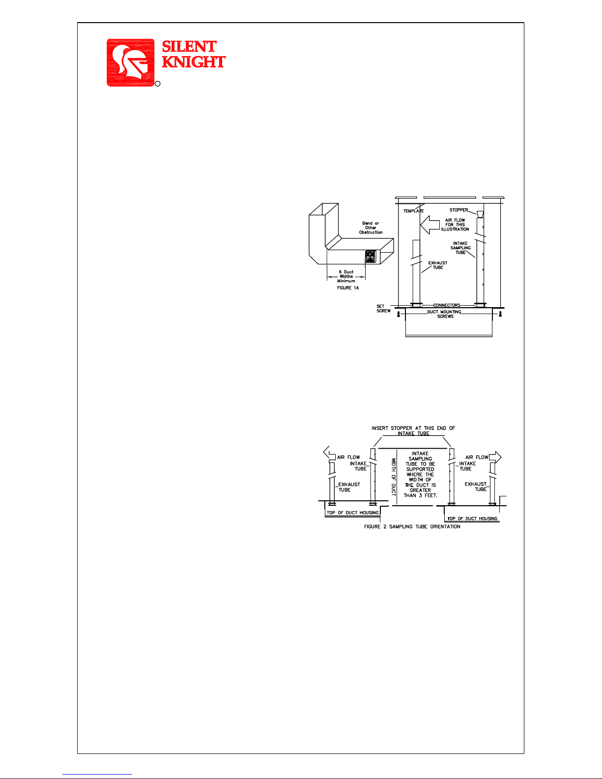
The intake sampling tube consists of a piece of steel piping with
a series of holes drilled the entire length of the tube and should
extend the entire width of the duct. The holes must be facing
into the air flow (see Figure 2). The exhaust tube consists of a
piece of steel piping approximately 7-1/2" long.
1. Remove paper backing from mounting template AP 121 (packaged in installation kit) and
affix to duct at desired location.
2. Using template as a guide, drill 4 mounting holes (3/32" diameter) for duct mounting
screws (4 #12 x 1/2" sheet metal screws packaged in installation kit). Drill or punch holes
for sampling tubes in air ducts (1-3/8" diameter), using template as a guide. Clean all holes.
Duct Smoke Detector Location
Requirements: To prevent false alarms the detectors should
not be mounted in areas of extreme high or low temperatures,
in areas where high humidity exist, or in areas where duct air
may contain gases or excess dust. The duct detector should,
when possible, be located a minimum of six duct widths
downstream from a source of turbulence (bends, inlets, or
deflection plates). At these locations, air flow is less turbulent
and the air/smoke mixture should be more homogenous.
Refer to NFPA 90A, 72, and 101 for more information. See
Figure 1A and 1B.
Exception: Where it is physically impossible to locate
the duct detector accordingly, the duct detector can be
positioned closer than six duct widths, but as far as
possible from inlets, bends, or deflection plates.
These are Installation Instructions (DWG.# HA-06-094) for the Duct Housing customized as follows:
SD505-DUCT Duct Housing with the SD505-APS Analog Photoelectric Smoke Sensor*
SD505-DUCTR Duct Housing with the SD505-APS Analog Photoelectric Smoke Sensor & Relays*
SD505-DTS-K Remote Test Switch
INSTALLATION INSTRUCTIONS FOR THE
DUCT SMOKE DETECTOR
A. DUCT PREPARATION
C. SAMPLING TUBE ASSEMBLY (See Figure 2)
The Duct Detectors are designed for use in ducts where the air velocities are
from 300 to 4000 feet per minute. Verify this by checking specifications of
installation and if necessary, use an Alnor Model 6000P velocity meter (or
equivalent) to check the air velocity. See Figure 2 for sampling tube
orientation to air flow direction.
B. VERIFY AIR FLOW AND DIRECTION
FIGURE 1B: DUCT HOUSING MOUNTING
TOP OF DUCT HOUSING
To verify proper sampling of air, use a Dwyer Model 4000 differential pressure gauge (or equivalent). See Figure 3 for
gauge connections. The pressure differential between input sampling tube and exhaust tube should be greater than
0.01" of water and less than 1.2" of water.
E. MOUNT THE DUCT HOUSING(See Figure 1B & 2)
Move duct housing/sampling tube assembly to desired location. Use 4 mounting screws (4 #12 x 1/2" sheet metal screws,
packaged in installation kit) to secure the housing to the air duct.
1. Sampling tube connectors are equipped with set screws, which allow the tubes to be mounted only in directions shown in
Figure 2. Establish proper orientation considering airflow direction.
2. Insert intake and exhaust tubes into connectors, align set screw to set screw hole in tubes andtighten firmly.
1. Cut the intake sampling tube to the desired length.
2. Firmly insert the stopper (packaged in installation kit) in the end of the INTAKE sampling tube.
INTAKE SAMPLING TUBES STANDARD LENGTHS:
Installation Instructions (P/N 1700-09882 HA-06-094) Page 1 of 3
F. VERIFY AIR SAMPLING (See Figure 3)
D. MOUNT SAMPLING TUBES (See Figure 2)
Specifications subject to change without notice. *September 2014
For duct widths of 1.0' to 2.5'
For duct widths of 2.5' to 5.0'
For duct widths of 5.0' to 10.0'
SD505-T2
SD505-T5
SD505-T10
I. LOCATION REQUIREMENTS
R
by Honeywell
1. With power source de-energized and the smoke detector not installed, wire
all connections per engineering drawings. Refer to the applicable figures below
depending on your duct housing model number.
2. With all wiring in place, install the detector head.
3. Energize the duct detector.
Wiring must conform to applicable local codes, ordinances and regulations
covering these types of devices. Wire the detectors according to the
engineering drawings for the particular job requirements. These detectors
are not intended for open area protection, nor should they be used for
open air protection. Refer to NFPA 90A and NFPA 72 for general and
additional information on Duct Smoke Detectors concerning operation
and installation. Terminals are suitable for up to #14 gauge wire.
B. DETECTOR WIRING
A. GENERAL INFORMATION
III. ELECTRICAL INSTALLATION
FIG. 3 AIR SAMPLING
VERIFICATION
EXHAUST TUBE
HOLE &
CONNECTOR
LOW PRESSURE
SIDE
DWYER #4000 DIFFERENTIAL
PRESSURE GAUGE(OR
EQUIVALENT) WITHTUBING
AND SIZE 0 RUBBERSTOPPERS
(HA PART# 0700-01118).
HIGH PRESSURE
SIDE
INTAKE TUBE
HOLE &
CONNECTOR
Specifications subject to change without notice. *September 2014
Installation Instructions (P/N 1700-09882 HA-06-094) Page 2 of 3
NOT USED
The SD505-DUCT is not a self-contained sensor.
This product is compatible only with fire alarm
control panels that utilize Silent Knight's Digital
Communications Protocol.
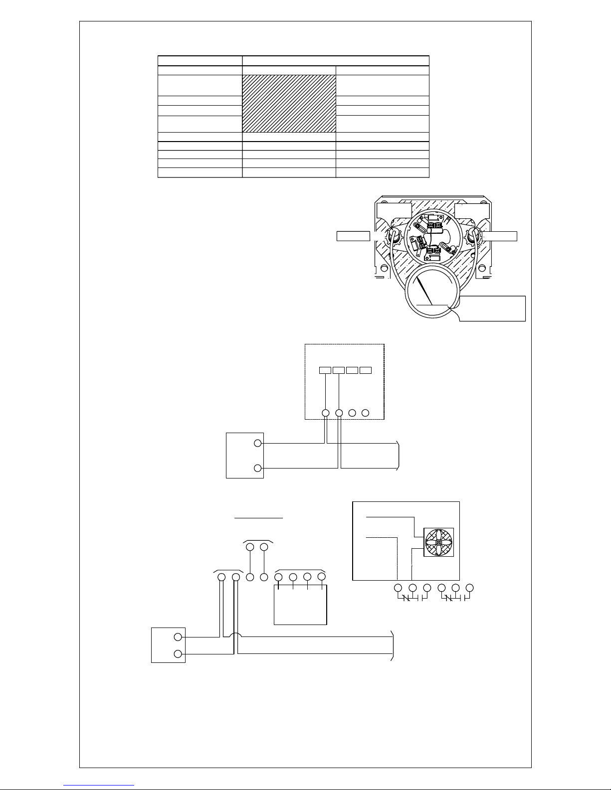
C. WIRING DIAGRAMS
UL LISTED
CONTROL PANEL
LOOP INTERFACE
S (+)
SC (-)
STANDBY and ALARM current should
be 0.55mA
TO NEXT
SENSOR
-R +RL2L1
1 2 3 4
ANALOG SENSOR
Terminate Remote Accessories as indicatedabove (if required).
This is not a self-contained stand alone detector.
A U.L. Listed Analog Addressable Fire System is required.
ANALOG ADDRESSABLE
FIELD LOOP WIRING
OBSERVE POLARITY
INPUT VOLTAGE
24 V.D.C.
S (+)
SC (-)
UL LISTED
CONTROL PANEL
A.A.
CONTROL
PANEL
ADDRESSABLE
LOOP
13 14
20 mA Standby
62mA Alarm
1 2
+-
SD505-DUCTR WIRING DIAGRAM
SUPPLY VOLTAGE
TO NEXT SENSOR
OR RETURN
TO CONTROL PANEL
TROUBLE
10.0A @ 250VAC
6
10
ALARM CONTACTS
10.0A @ 250VAC
NONCC
3 4 5
NO
C
NC
8
7
FAN
REMOTE TEST
SWITCH
(Test function only. Does not reset.)
FAN SHUTDOWN EXAMPLE
Test
SW GND PILOT
LED ALARM
LED
911 12
SD505-DTS
SD505-DUCT WIRING DIAGRAM
Maximum SLC Resistance
SLC Input Current
Aux. Power Input Current
Trouble Relay Contact Rating
Operating Voltage
Alarm Relay Contact Rating
Air Velocity Rating
Humidity
Operating Temperature
0.5mA
10% ~ 85% RH Non-Condensing
50 Ohms
32F ~ 100F
2.5A @ 30VDC
24VDC
10A @ 24VDC
SPECIFICATIONS
20mA Standby
62mA Alarm
RATING
SD505-DUCT
300 ~ 4000 ft./min.
0.5mA
10% ~ 85% RH Non-Condensing
50 Ohms
32F ~ 100F
300 ~ 4000 ft./min.
SD505-DUCTR
SPECIFICATIONS
10A @ 115VAC
10A @ 240VAC

12 Clintonville Road
Northford, CT 06472
Phone: 203-484-7161 * Fax: 203-484-7118 Specifications subject to change without notice.*September 2014
Installation Instructions (P/N 1700-09882 HA-06-094) Page 3 of 3
R
by Honeywell
SD505-DUCTR AND SD505-DTS-K
WIRING CONNECTIONS
REFER TO INSTALLATION INSTRUCTIONS(HA-06-094)
* SILENT KNIGHT DETECTORS ARE INTENDED FOR USE WITH AIR DUCTVELOCITIESFROM300TO4000FEETPERMINUTE.
VERIFY THIS BY CHECKING THE SPECIFI CATIONS OF HVAC INSTALLATIONANDIFNECESSARY,USEANALNOR
MODEL 6000P VELOCI TY METER OR EQUIVALENTTOCHECKAIRVELOCITY.
* PRESSURE DIFFERENTIAL MEASUREMENTS SHOULD BE MADE USINGADWYERPRESSUREGAGE(CATALOG
#2003 - 3" WATER FULL SCALE) TO INSURE AIR FLOW IN THISCHAMBER. THEPRESSUREDIFFERENTIAL
BETWEEN INPUT AND EX HAUST TU BE SHOULD B E BETWEEN0.01AND1.2INCHESOF WATER.
* DO NOT INSTALL WHERE AMBIENT TEMPERATUREEXCEEDS100°F(38°C).
FOR TERMINALS 3,4,5,6,7,8DO NOT USE LOOPED WIRE UNDER TERMINALS. BREAK WIRE RUN TO PROVIDE SUPERVISION OF CONNECTION.
CAUTION:
24 VDC
(+) (-) NC COM NO NC COM NO
ALARM
TROUBLE
TEST GND PILOT ALARM SLC- SLC+
SW LED LED
+ BASE -
BJ
5
910
105
50K
730
473 702
N4
MM
76A
N4
2447W9
A
VDE
EBYEBYEBYEBYEBY
EBY
2127H1
A
Bot t om View
MADE I N INDONESIA
105
335
2004
105
2004
1P
9
1V H
BJ
5
673 1016E
C2K
G43
673
10
16E
104
105 50K 730
105
50K
730
471
473
910
1V H
105
105
V104
103
D217
725S
D217
725S D217
725S
102
153
104
153
473
A7
5
473
A7
5
2T
105
50K
730
473
473
105
474
473
LM393
75M
CR7RG4
V104
153
472
153
105
50K
730
473
474
2004
2004
152
152
A7
5
1V H 1P
9
472
2T
1P
9
702
152
473
152
473
473
2T
A7
5
A7
5
TEST GND PILOT ALARM
LED LED
Class A (Style 6) Wiring
SC-
SLC OUT IN
TEST GND PILOT ALARM SLC- SLC+
SW LED LED
EBYEBY
EBY
TEST GND PILOT ALARM SLC- SLC+
SW LED LED
EBYEBY
EBY
TEST GND PILOT ALARM SLC- SLC+
SW LED LED
Silent Knight Control Panel
S+ SC-
SLC S+
SC-
SLC OUT IN
S+ SC-
SLC S+
EBYEBY
EBY
Class B (Style 4) Wiring
Silent Knight Control Panel
This manual suits for next models
2
Table of contents
Other SILENT KNIGHT Smoke Alarm manuals


Popular Smoke Alarm manuals by other brands

BRK electronic
BRK electronic P H O T O & I O N 3120B Technical specifications

ELRO
ELRO FS1801 instruction manual

Silent Call Communications
Silent Call Communications SD4-SS Installation and operation manual

Quell
Quell Q9080 manual

SB
SB SB-SK540 quick start guide
Brooks
Brooks Firetracker FT1-SB System manual


Uplink
Uplink 4555 Installation & user guide

Bosch
Bosch D1255RB/D1256RB/D1257RB installation instructions

teko
teko Astra-Z-2345 Operation manual

Sunmatic
Sunmatic Housegard PEBBLE MINI user manual

System Sensor
System Sensor Innovair flex 2D51 Installation and maintenance instructions

Swegon
Swegon TBLZ-1-72-a GOLD installation instructions