We reserve the right to alter specifications. www.swegon.com 3
GB.TBLZ172.190411
• Open the cover above the junction hood by lifting the catch.
• Insert the cable through any cable grommet.
When using another type of grommet, remove them premounted
by first pressing through one side and then through the other
(1-2).
• Connect the cables according to the wiring diagram in Section 6.
1
2
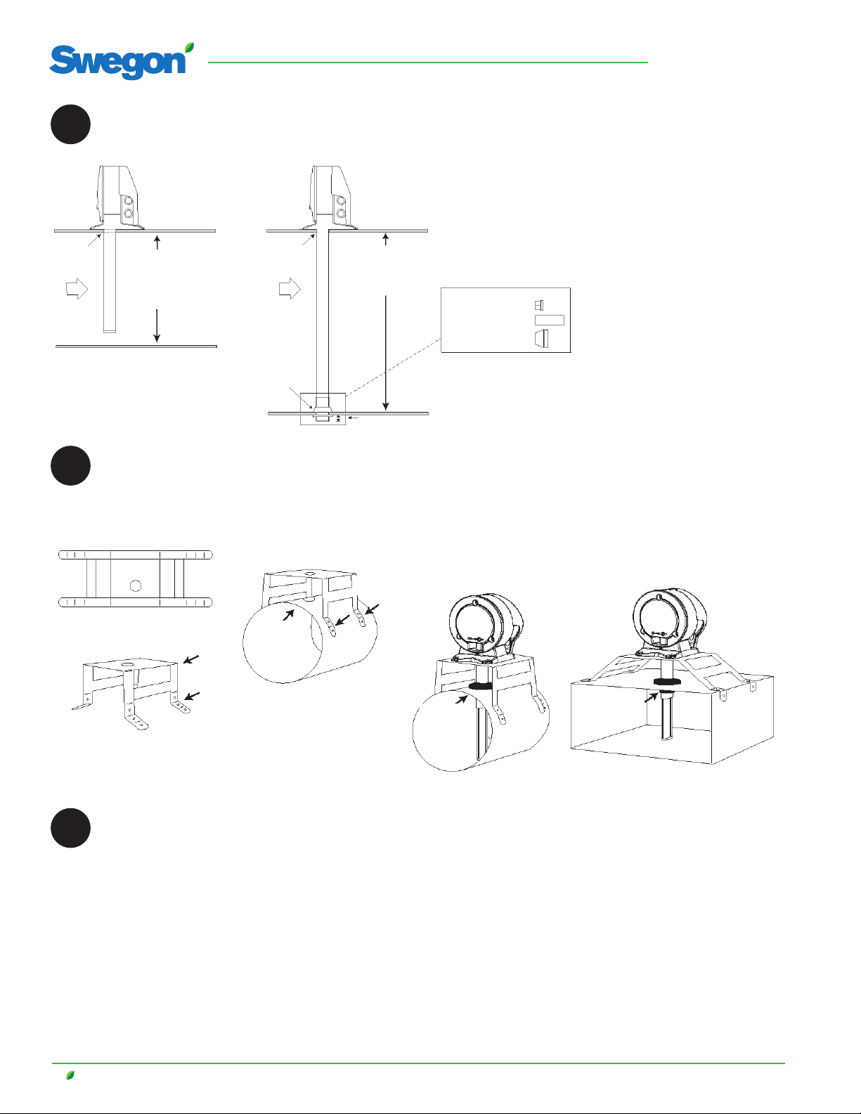
Drill holes in the duct.
• Make holes without 38 mm installation bracket.
• Make holes with 51 mm installation bracket (see
point 9).
3
Do not cut this end!
• Measure the ventilation duct.
• Cut the tube.
• The tubes must cover at least 90% of the duct’s width.
Detectors with venturi tubes of 600 mm are intended for ducts
with a max. duct width of 600 mm.
• Insert the end plug.
• Insert the seal onto the tube.
• Insert the tube into the bottom of the detector box.
• Lock the tube using the stop screw
4
• Install the tube and detector on the duct.
• Secure the detector box at 3 points at the markings of the
arrows.
Important! IMPORTANT!
The direction arrows (see the shape of the detector’s base or the top
of the housing) must point in the same direction as the air flow in
the duct.
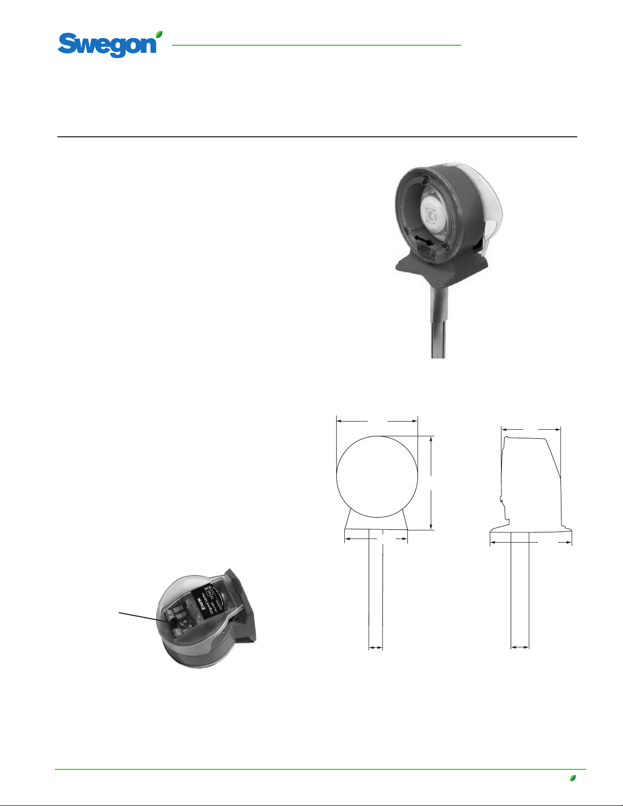
End plug
Stop screw
Seal
5Flow indicator.
The detector is equipped with an indicator, a red plastic
tab, which, when the detector is correctly installed,
swings out due to the air flow.
6Electrical installation.
Important!
If the indicator does not
move, consider moving
the detector or install a
fan tube.
Flow indicator
Venturi tube with auxiliary fan
7Performance checks.
Check the detector using the smoke detector tester in
spray form.
• Move the "test hole plug" to the side
and then quickly spray.
In the event of a tripped alarm, the
LED shines red on the circuit board and
the detector. In the event of a tripped
service alarm, the LED shines green on
the detector and yellow on the circuit
board.
• Reinstall the test hole plug.
Important!
Do NOT drill holes for signs or similar in the plastic cover. This can
cause leakage that seriously affects the function of the detector.