Silent Witness V25 ArmorDome User manual

V25 Series
ArmorDome™
CCTV Camera
User Guide

Contents
Overview . . . . . . . . . . . . . . . . . . . . . . . . . . . . . . . . . . . . . . . . . . . . . . . . . . . 1
Before You Begin . . . . . . . . . . . . . . . . . . . . . . . . . . . . . . . . . . . . . . . . . . . . . . 1
Unpacking and Inspection . . . . . . . . . . . . . . . . . . . . . . . . . . . . . . . . . . . . . 1
Equipment Required . . . . . . . . . . . . . . . . . . . . . . . . . . . . . . . . . . . . . . . . . 1
Initial Setup . . . . . . . . . . . . . . . . . . . . . . . . . . . . . . . . . . . . . . . . . . . . . . . . . 2
Disassembling the Camera . . . . . . . . . . . . . . . . . . . . . . . . . . . . . . . . . . . . . . . 2
Wall Mount Setup . . . . . . . . . . . . . . . . . . . . . . . . . . . . . . . . . . . . . . . . . . . . . . 3
Ceiling Mount Setup . . . . . . . . . . . . . . . . . . . . . . . . . . . . . . . . . . . . . . . . . . . . 4
Installation . . . . . . . . . . . . . . . . . . . . . . . . . . . . . . . . . . . . . . . . . . . . . . . . . . 6
Mounting the Camera on a Wall or Ceiling. . . . . . . . . . . . . . . . . . . . . . . . . . 6
Mounting the Camera in an Electrical Box. . . . . . . . . . . . . . . . . . . . . . . . . . . 7
Wiring . . . . . . . . . . . . . . . . . . . . . . . . . . . . . . . . . . . . . . . . . . . . . . . . . . . . . . . 7
Aiming and Focusing . . . . . . . . . . . . . . . . . . . . . . . . . . . . . . . . . . . . . . . . . . . 8
Changing the Quick Change Lens . . . . . . . . . . . . . . . . . . . . . . . . . . . . . . . 9
Dip Switch Functions (Color Cameras) . . . . . . . . . . . . . . . . . . . . . . . . . 10
Adjustment Method (Color Cameras) . . . . . . . . . . . . . . . . . . . . . . . . . . 11
White Balance Adjustment Method (Color Cameras) . . . . . . . . . . . . . 11
Manually Setting Shutter Speed (Color Cameras) . . . . . . . . . . . . . . . . . 12
Dip Switch Functions (Monochrome Cameras) . . . . . . . . . . . . . . . . . . 13
Adjustment Method (Monochrome Cameras) . . . . . . . . . . . . . . . . . . . 13
Adjusting the Line Lock (Vertical Phase) for 24 VAC Operation . . . . . 14
Adjusting the Backlight Compensation . . . . . . . . . . . . . . . . . . . . . . . . . 14
Installing the Front Plate and Dome . . . . . . . . . . . . . . . . . . . . . . . . . . . . . . 14
Routine Maintenance . . . . . . . . . . . . . . . . . . . . . . . . . . . . . . . . . . . . . . . . . . 14
Replacing the Dome . . . . . . . . . . . . . . . . . . . . . . . . . . . . . . . . . . . . . . . . . . . 15
Solving Common Technical Issues . . . . . . . . . . . . . . . . . . . . . . . . . . . . . 16
Service . . . . . . . . . . . . . . . . . . . . . . . . . . . . . . . . . . . . . . . . . . . . . . . . . . . . 17
Specifications . . . . . . . . . . . . . . . . . . . . . . . . . . . . . . . . . . . . . . . . . . . . . . 18
Cable Guidelines . . . . . . . . . . . . . . . . . . . . . . . . . . . . . . . . . . . . . . . . . . . . 20
Mounting Template . . . . . . . . . . . . . . . . . . . . . . . . . . . . . . . . . . . . . . . . . 21
V25 Model Numbers . . . . . . . . . . . . . . . . . . . . . . . . . . . . . . . . . . . . . . . . 22
Regulatory Compliance. . . . . . . . . . . . . . . . . . . . . . . . . . . . . . . . . . . . . . . 23
FCC Statement (U.S.A.) . . . . . . . . . . . . . . . . . . . . . . . . . . . . . . . . . . . . . . . . 23
Industry Canada Notice . . . . . . . . . . . . . . . . . . . . . . . . . . . . . . . . . . . . . . . . 23

1
Overview
The unobtrusive, low-profile design of the V25 ArmorDome™ CCTV Camera is
ideal for indoor and outdoor installations in commercial and residential venues.
Before You Begin
WARNING! The use of CSA Certified/UL Listed Class 2
power adapters is required to ensure
compliance with electrical safety standards.
Unpack Everything
Check that the items received match those listed on the order form and packing
slip. The V25 packing box should include, in addition to this Installation Guide:
• One security hex key
• Four #6-32 x 3/4 in. plated steel, Phillips head machine screws
• One #6 nylon washer
• One #6-32 x 3/8 in. stainless steel, Phillips head machine screw
If any parts are missing or damaged, please contact the dealer you purchased the
camera from, or call Silent Witness Customer Service. See “Service” on page 17.
Equipment Required
You will require the following tools to complete the installation:
• Phillips screwdriver
• Side-cutters
Please read this guide carefully before you install
the V25 ArmorDome CCTV Camera.
Keep this guide for future reference.

Document 920.0090 Rev 3.00 April 16, 2002
2
Initial Setup
Before installing the V25 Camera, you must first:
• Disassemble the camera.
• Set up the camera for mounting on a wall or a ceiling.
Disassembling the Camera
To disassemble the camera:
1. Use the security hex key provided to remove the three #6-32 x 3/8 in. machine
screws securing the V25 front plate and dome to the base (see Camera
Components). Set aside the screws.
2. Use a Phillips screwdriver to remove the two #6-32 x 1/4 in. machine screws
that attach the camera gimbal to the gimbal support bracket.
Do not remove the camera carrier from the gimbal at this time. Also, do not
disconnect the wires from the camera.
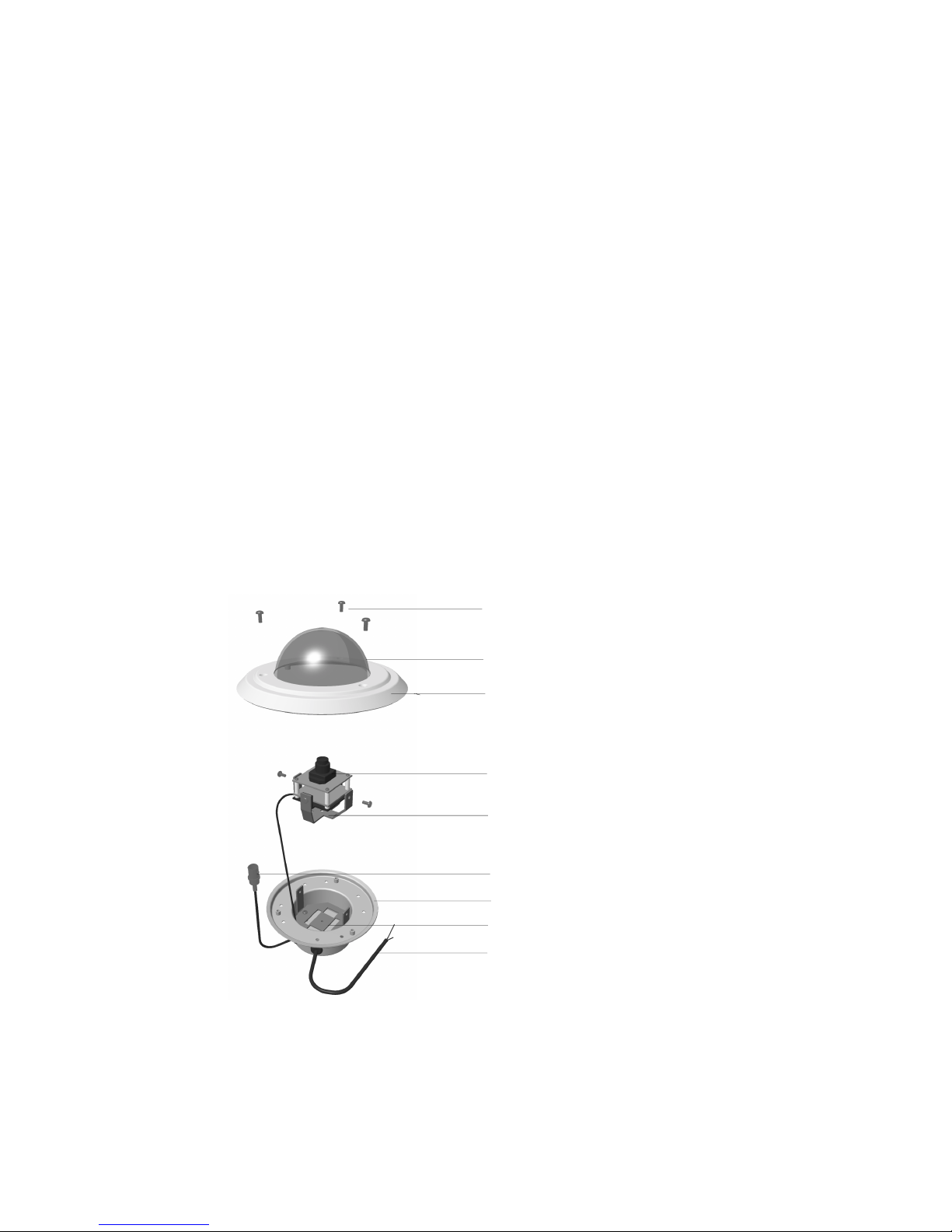
Figure 1 Camera Components
If you are mounting the V25 Camera on a wall, proceed to Wall Mount Setup. If you
are mounting the V25 Camera on a ceiling, proceed to Ceiling Mount Setup.
#6-32 x 3/8 in. Security head
machine screws (x3)
Dome
Front plate
Camera and carrier
Gimbal
Video output: female BNC
Base
Gimbal support bracket
Power input cable

3
Wall Mount Setup
When the V25 Camera is mounted on a wall, the camera carrier can be adjusted to
pan and tilt.
Once you have disassembled the camera, prepare the camera for mounting on a
wall:
1. Use a pair of side-cutters to remove the perforated square in the gimbal
support bracket (see Wall Mount Setup). Discard this square. This allows full
motion of the camera gimbal.
2. Use a Phillips screwdriver and two #6-32 x 1/4 in. machine screws to attach
the camera gimbal and camera carrier to the modified gimbal support bracket.
The V25 Camera is now set up for mounting on the wall. Proceed to Installation on
page 6.
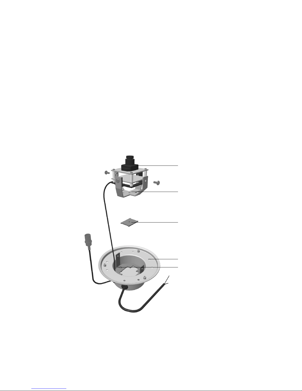
Figure 2 Wall Mount Setup
Camera and carrier
Gimbal
Discard center square
Base
Gimbal support bracket
(center square removed)

Document 920.0090 Rev 3.00 April 16, 2002
4
Ceiling Mount Setup
When the V25 Camera is mounted on the ceiling, the camera carrier can be
adjusted to rotate and tilt.
Once you have disassembled the camera, prepare the camera for mounting on a
ceiling:
1. Remove both arms from the gimbal support bracket by holding the end of the
arm and bending it back and forth until it breaks off (see Figure 3). Do not
remove the center square from the gimbal support bracket.
2. Use a Phillips screwdriver to remove the two #6-32 x 1/4 in. machine screws
that attach the camera carrier to the gimbal.
3. Use side-cutters to remove the two perforated arms of the gimbal.
4. Attach the gimbal to the gimbal support bracket (see Figure 3) using one #6-32
x 3/8 in. machine screw and a #6 nylon washer (provided). Tighten the screw.
Caution The nylon washer must be mounted between the gimbal
and the gimbal support bracket to allow the gimbal to
rotate clockwise without binding.
5. Use two #6-32 x 1/4 in. machine screws to attach the camera carrier to the
gimbal.
Caution Line-lock cameras have an electrically isolated camera
carrier to prevent ground loop problems. Ensure the nylon
bushings and insulating washers are installed as shown in
Figure 3.
The V25 Camera is now ready for mounting on a ceiling. Proceed to Installation on
page 6.

5
Figure 3 Ceiling Mount Setup Showing Electrical
Isolation of Line Lock Camera Carrier
Nylon bushing
Insulating washer
Gimbal
#6-32 x 1/4 in. machine screw
Camera and carrier
#6-32 x 3/8 in. machine screw
Gimbal (perforated
arms removed)
#6 nylon washer
Base
Gimbal support bracket
(arms removed)

Document 920.0090 Rev 3.00 April 16, 2002
6
Installation
The V25 Camera is designed to be flush mounted on a panel or in a standard deep
double-gang electrical box. The camera can be located indoors or outdoors, on a
wall or ceiling, in accordance with the current Electrical Code or any national wiring
rules that apply.
Follow the Initial Setup procedure before installing the V25 Camera.
Mounting the Camera on a Wall or Ceiling
To mount the V25 Camera on a wall or ceiling panel:
1. Mark and drill out mounting holes in the wall or ceiling panel (see Figure 4),
using the mounting template shown on page 21.
2. Insert the camera base into the mounting hole.
3. Secure the camera to the mounting panel using four #6-32 self-tapping screws
(not provided).
Note An optional V25 Backing Plate Kit is available to mount the V25
Camera in a removable ceiling panel as shown in Figure 4. Please
contact Silent Witness Sales for more information.
Figure 4 Wall/Ceiling Mount Installation
Backing plate
(optional)
Mounting panel
Video output
Power input
V25 base
#6-32 mounting
screws (x4)

7
Mounting the Camera in an Electrical Box
To mount the V25 Camera in an electrical box:
1. Install the V25 in the electrical box (see Figure 5).
2. Secure the camera in place with the four #6-32 x 3/4 in. plated steel, Phillips
head machine screws provided.
Figure 5 Electrical Connections (Electrical Box)
Wiring
Read the Cable Guidelines on page 20 for cable gauge and length recommendations.
To connect the wiring:
1. Pull the video and power supply cables through the conduit to the electrical
box or panel mount location.
Standard deep double-gang
electrical box
Pan axis must be vertical
for wall mount installation
TOP (picture) label must
be on top of lens mount
Video output: female BNC
#6-32 x 3/4 in. screws (x4)
Power input cable
RED: +DC
BLACK: -DC
This camera is polarity independent for AC operation
(see Adjusting the Line Lock (Vertical Phase) for 24 VAC
Operation).
To ensure the vertical alignment is the same for all cameras,
make all power connections the same phase.
Note

Document 920.0090 Rev 3.00 April 16, 2002
8
2. Install a male BNC connector on the video cable coming from the video
monitor or CCTV system.
3. Connect the video cable to the female BNC connector and cable coming from
the base of the V25 Camera.
4. Connect the AC or DC power wires to the red and black wires coming from
the base of the V25 Camera, as shown in Figure 5.
WARNING! The use of CSA Certified/UL Listed Class 2
power adapters is required to ensure
compliance with electrical safety standards.
Caution For outdoor installations, or any installation where water
may be a problem, ensure that all electrical connections are
covered to prevent short circuits or contamination.
Aiming and Focusing
To aim the V25 Camera:
1. Turn on the camera power and monitor the video signal. Adjust the camera
carrier to the desired view.
Note The TOP (of picture) label must be on the top of the lens mount
to ensure the video image is upright.
2. If necessary, turn the lens to adjust the focus (see Figure 6).
Cameras with a 12 mm lens may need the lens rotated approximately 1/4 of a
turn counterclockwise to allow for the magnification properties of the dome.
Hold the front plate and dome in position to check the focus.
3. Hold the front plate and dome in place to ensure that it does not interfere with
the camera or block the camera view. If the enclosure cover does interfere
with the camera, slide the camera support bracket away from the camera lens
(toward the terminal board).
If vibration is a significant factor, use Loctite™ Serviceable Threadlocker (or
equivalent) to secure all camera adjustments.

9
Changing the Quick Change Lens
Some V25 Cameras have a quick change lens mount, designed to provide a fast and
easy way to change the camera lens. To change the quick change lens:
1. Remove the quick change lens:
a. Turn the lens holder 45° counterclockwise (see Figure 6).
b. Pull the lens holder out of the lens mount.
2. Install a new quick change lens:
a. Insert the lens holder into the lens mount. Align the locking lugs on the
lens holder with the grooves in the quick change lens mount (see Figure 6).
b. Turn the lens holder 45°clockwise to lock the lens holder in the lens
mount.
c. If necessary, turn the lens to adjust the focus.
Note Lenses are pre-focused at the factory but may require a final
adjustment after installation.
Figure 6 Lens Mount and Quick Change Lens
Removing quick change lens Installing new quick change lens
Lens mount
Lens holder Lens
Grooves
Locking lug (x2)

Document 920.0090 Rev 3.00 April 16, 2002
10
Dip Switch Functions (Color Cameras)
Figure 7 Color Camera Switch Settings
ON
OFF
12 345678 910
ON
OFF
GAMMA
AE
FLON
BLC
IRIS
N/U *
AGC MAX
AWB1
AWB2
AWB3
Push lock
* N/U = Not used.
Leave in Off position.
Not used
Line lock
Factory (default) settings
Fixed lens camera
1 2345678910
adjustment
= ON (up) = OFF (down)

11
Adjustment Method (Color Cameras)
White Balance Adjustment Method (Color Cameras)
Switch
no.
Function Off On
1 GAMMA Off (0.45) On (1.0)
2AE(Automatic
Exposure)
Off On (see Manually Setting Shutter
Speed (Color Cameras))
3 FLON (Flicker Less) Off On
4 BLC (Backlight
Compensation)
Off On (Center window)
5 IRIS Electronic IRIS Not used
6 Not used Not used Not used
7 AGC 4 dB 26 dB
Symbol SWB8
AWB1
SWB9
AWB2
SW10
AWB3
AWB Off Off Off
ATW Off On Off
Push lock Off On On *
Indoor (3200°K) On Off On
Outdoor (6500°K) On On On
* To manually set Push lock feature: place a white background in front of
camera and press “Push lock” switch.

Document 920.0090 Rev 3.00 April 16, 2002
12
Manually Setting Shutter Speed (Color Cameras)
To manually set the shutter speed, turn switch #2 to the ON position; then set
switch #3, #4, and #5 for the desired shutter speed (see Figure 7).
Note FLON and BLC can be set when switch #2 is set to the OFF
position.
Caution Before you adjust the shutter speed, it is important that
you understand how the settings can affect the scene detail.
Shutter
speed(s)
SW2
AE
SW3
FLON
SW4
BLC
SW5
IRIS
1/50 (PAL)
1/60 (NTSC)
On Off Off Off
1/100 (NTSC)
1/120 (PAL)
On Off Off On
1/250 On Off On Off
1/500 On Off On On
1/1000 On On Off Off
1/2000 On On Off On
1/4000 On On On Off
1/10000OnOnOnOn

13
Dip Switch Functions (Monochrome Cameras)
Figure 8 Monochrome Camera Switch Settings
Adjustment Method (Monochrome Cameras)
Switch
no.
Function Off On
1 IRIS Control Not used Electronic IRIS
2BLC Off On
3,4 FLON (Flicker Less) Off On
5 AGC 1 dB 26 dB
ON
OFF
1 2 3 4 5
IRIS
BLC
FLON
AGC
Line lock
Factory (default) settings
Not used
adjustment
= ON (up) = OFF (down)
ON
OFF
1 2 3 4 5

Document 920.0090 Rev 3.00 April 16, 2002
14
Adjusting the Line Lock (Vertical Phase) for 24 VAC
Operation
In multiple camera installations, wire all cameras to the same phase. This will ensure
that the vertical phase of all cameras are aligned. Phase adjustment may be necessary
to prevent picture roll when switching between cameras.
Note If the phase cannot be adjusted to prevent picture roll, reverse
the power polarity.
To adjust the vertical phase:
While switching between the two cameras, turn the Line-lock adjustment screw
(see Figure 7) on one camera until there is no vertical roll.
Adjusting the Backlight Compensation
The backlight compensation (BLC) adjusts the electronic shutter speed of the
camera based on the light levels in specific areas of the scene. This adjustment
provides better image quality for scenes that are unevenly lit.
To adjust the BLC, set the BLC switch to ON (see Figure 8). Center window
weighted.
Installing the Front Plate and Dome
Secure the front plate and dome to the base with the three #6-32 5/8 in. security
machine screws, using the hex key provided.
Routine Maintenance
Use regular liquid cleaners to remove most dirt and grime from the dome.
Caution Do not use harsh or abrasive cleaners which can scratch
the polycarbonate dome and reduce visibility of the
camera.
If the camera view is obstructed by scratches, remove the front plate and rotate it
120° to find an unscratched part of the dome.

15
Replacing the Dome
If the polycarbonate dome is damaged or scratched beyond use, contact your
distributor or salesperson to order a V25 Dome Replacement Kit.
To replace the V25 dome:
1. Use the security hex key (provided) to remove the three #6-32 5/8 in. machine
screws securing the V25 plate and dome to the base (see Figure 9). Put aside.
2. Use a Phillips screwdriver to remove the three #6-32 1/4 in. machine screws
that attach the dome retainer plate to the front plate.
3. Remove the damaged dome and replace it with the new dome and gasket. The
gasket should be between the dome and the V25 base (see Figure 9).
4. Use a Phillips screwdriver to attach the dome retainer plate to the V25 front
plate with the three #6-32 1/4 in. machine screws you removed in step 2.
5. Use the security hex key to replace the three #6-32 x 3/8 in. machine screws
to attach the front plate and dome to the base.
Figure 9 Dome Replacement
#6-32 X 3/8 in. security
head machine screws (x3)
Front plate
Polycarbonate dome
Silicone gasket
(glued to dome)
Retainer plate
#6-32 x 1/4 in. Phillips-head
machine screws (x3)

Document 920.0090 Rev 3.00 April 16, 2002
16
Solving Common Technical Issues
Call Silent Witness Service Department for additional assistance (see Service for
contact numbers).
No Video
❐Check that the power supply voltage is within the operating specifications
for your camera model. See Specifications for details.
❐Connect a video monitor directly to the V25 video output cable to eliminate
video problems that could be caused by other equipment such as video
switches.
❐Check the video connections to the monitor or CCTV system.
❐Check the camera connections to the V25 power supply.
Fuzzy Video
❐Check the video ground connections.
❐Check for ground loops.
Rolling Picture (Line-Lock Cameras Only)
❐Adjust the phase as described in Adjusting the Line Lock (Vertical Phase) for 24
VAC Operation.
❐If the phase cannot be adjusted to prevent picture roll, reverse the power
supply polarity.

17
Service
Subject to the terms and conditions listed on the Product Warranty Card, during
the warranty period Silent Witness will repair or replace, at its sole option, free of
charge, any defective products returned prepaid.
In the event you have a problem with any Silent Witness product, please call
Custmer Service for assistance or to request a Return Authorization (RA)
number.
In the U.S.A. and Canada, call 1.800.893.9513.
Or call +1.604.574.1523.
Be sure to have the model number, serial number, and the nature of the problem
available for the technical service representative.
Prior authorization must be obtained for all returns, exchanges, or credits. Items
shipped to Silent Witness without a clearly identified Return
Authorization (RA) number may be refused.

Document 920.0090 Rev 3.00 April 16, 2002
18
Specifications
Note Specifications apply to all camera models, unless noted
otherwise.
Video Specifications
Pickup device: 1/3 in. CCD
Electronic iris: 1/60 (1/50) to 1/100,000 seconds
Surge protection: 1.5 kW transient
Video output impedance: 1 Vp-p @ 75 Ω
Video signal:
Monochrome Standard EIA or CCIR
Color Standard NTSC or PAL
Resolution: High RES Standard RES
Monochrome 570 TV lines 410 TV lines
Color 480 TV lines 350 TV lines
Signal to noise ratio: High RES Standard RES
Monochrome 50 dB 50 dB
Color better than 51 dB better than 51 dB
Sync system: 12 VDC Internal
24 VAC External (Line Lock)
Light sensitivity: High RES Standard RES
Monochrome 0.05 lux @ f1.4
(0.10 lux @ f2.0)
0.05 lux @ f1.4
(0.10 lux @ f2.0)
Color 0.5 lux @ f1.2 0.4 lux @ f1.2
Power Requirements
Warning The use of CSA Certified/UL Listed Class 2 power adapters is
required to ensure compliance with electrical safety standards.
Current consumption and input voltage:
Monochrome (DC) 11 to 16 VDC, 150 mA @ 12 VDC
Monochrome (AC) 17 to 32 VAC, 2.5 W
Color and EXview (DC) 11 to 16 VDC, 250 mA @ 12 VDC
Color and EXview (AC) 17 to 32 VAC, 3.5 W
Operating Environment
Operating temperature:
Monochrome -4°F to 140°F (-20°C to 60°C)
Color and EXview -4°F to 122°F (-20°C to 50°C)
This manual suits for next models
1
Table of contents
Other Silent Witness Security Camera manuals

Silent Witness
Silent Witness SW001 User manual

Silent Witness
Silent Witness SWC40 Series User manual

Silent Witness
Silent Witness SW010 User manual

Silent Witness
Silent Witness SW021 User manual

Silent Witness
Silent Witness Night Hawk SWX45 User manual

Silent Witness
Silent Witness V60 Night Hawk User manual

Silent Witness
Silent Witness MagnaView V28R User manual

Silent Witness
Silent Witness SWX80 User manual

Silent Witness
Silent Witness SW2200 User manual