Silent Witness SWC40 Series User manual

SWC40 Series Surveillance Camera
User Guide
DOCUMENT 920.0083 REV 1.00

Notices - Warnings
Please read the instructions in this guide carefully before
you start installing the SWC40 Series Surveillance
Camera. Keep this guide for future reference.
Safety Warning
Any connection of this device to any equipment other
than the intended application may result in a safety
hazard, and/or defective operation, and/or equipment
damage.
Disclaimer
The information contained in this document is subject to
change without notice. Silent Witness Enterprises
Ltd., its affiliates, and/or its subsidiaries assume no
responsibility for errors and/or omissions contained in
this information.
Silent Witness Enterprises Ltd.
6554 - 176th Street
Surrey, BC V3S 4G5
Canada
© 1999 by Silent Witness Enterprises Ltd.

1
Table of Contents
Table of Contents.................................................. 1
Features................................................................. 2
Unpacking.............................................................. 4
Installation............................................................. 5
Mounting the Camera...............................................5
Wiring the Camera....................................................8
Aiming the Camera.................................................10
Adjusting Audio Sensitivity......................................12
Recording............................................................ 14
Recording Modes....................................................14
Using the Handheld Remote Control.......................16
Using the Camera Buttons......................................17
Playback .............................................................. 19
Playback Setup.......................................................19
Playback Recorded Images....................................20
Programming....................................................... 22
Record Menu..........................................................26
Intelligent Light Compensation (ILC) Menu.............28
Motion Menu...........................................................30
Display Menu..........................................................32
Alarm Menu............................................................34
Input Menu..............................................................36
Learning a New Remote Control Code ...................38
Routine Maintenance.......................................... 39
Window Replacement.............................................39
Troubleshooting.................................................. 40
Warranty and Service ......................................... 43
Regulatory Notices ............................................. 44
Specifications...................................................... 45
Mounting Template............................................. 47

2
Features
Thank you for purchasing the SWC40 Series
Surveillance Camera - the first all-in-one CCTV
solution.
The SWC40 Series is a high performance camera with
digital video recording and video motion detection all
within a single compact enclosure that is elegant yet
weather resistant and vandal proof.
The SWC40 Series features include:
qq Reliable, high performance, solid-state cameras
qq Digital video recording and playback
qq Digital video motion detection
qq Intelligent Light Compensation (ILC)
qq Programmable features and operating parameters
qq Handheld remote arming/disarming control
qq A built-in omnidirectional microphone
qq A tough, weather resistant, fiberglass reinforced
polycarbonate enclosure
qq Tamper proof enclosure fasteners
qq A universal camera mount for wall or ceiling
installations
qq Power input transient and reverse polarity protection
qq Easy installation and alignment
qq Easy maintenance

Features - continued
3
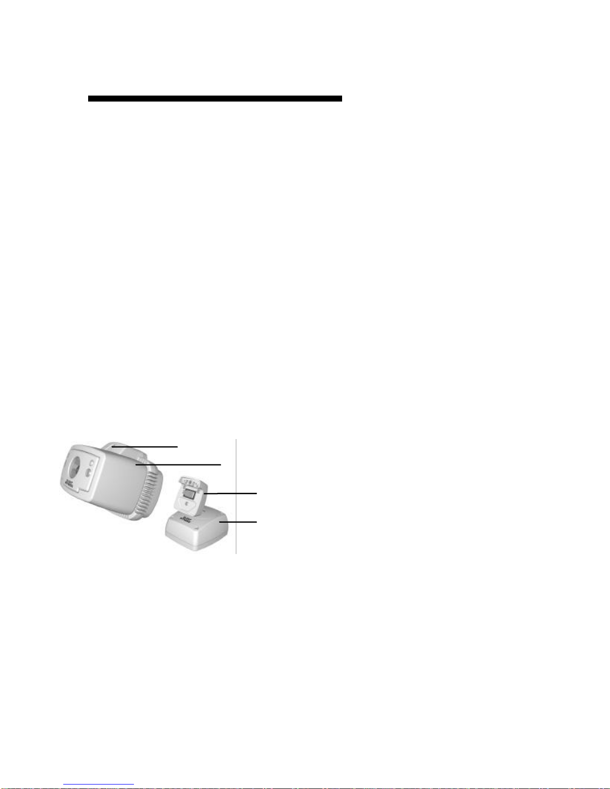
Remote control
Mounting base
Universal mount
Microphone
Camera enclosure
Ceiling mount

4
Unpacking
Open the SWC40 packing box and make sure that you
have the following items in addition to the User Guide
you are now reading:
qOne Product Warranty Card
qOne Quick Setup Guide
qOne SWC40 Series Camera (enclosure and
mounting base with factory installed
audio/video/power cable)
qTwo remote control units
qTwo power adapters
qOne Quick Change Lens Pack with 2.9, 6.9 and 8.0
mm lenses (3.5 mm pre-installed)
qOne video playback cable
qOne video adapter plug
qOne external input/output signal cable
qOne SWC40 Installation Kit including:
•One security hex key
•Four #10×1" Phillips self-tapping screws
•Four #10 neoprene washers
If you are missing any parts, please contact the dealer
you purchased the SWC40 from or call the Silent
Witness Service Department (see the Warranty and
Service section of this guide on page 43 for telephone
numbers).
5
Installation
Mounting the Camera
The SWC40 Series Camera is designed to be mounted
on a wall or ceiling. The SWC40 is weather sealed for
indoor or outdoor locations. The wiring can be surface
mounted or completely concealed to reduce the risk of
tampering.
The SWC40 pivot arm is designed to lock in position.
Do not try to adjust the pivot arm before loosening the
locking screws, as described in the following steps.
υTo mount the SWC40 on a wall or ceiling
1Use the security hex key provided in the SWC40
Installation Kit to loosen the #6-32×2" retaining
screw that secures the camera enclosure to the
connector block. The retaining screw is held in the
camera enclosure and should not be removed.
2Pull the camera enclosure away from the connector
block.
Caution:
Retaining screw
Camera enclosure
Connector block
Mounting base

Installation - continued
6
3Use the security hex key to remove the four
#6-32×1¼" machine screws securing the cover to the
mounting base. Position the connector block as
shown below and remove the cover.
4If you do not intend to use the external arming or
triggering inputs or the alarm output signals, skip
this step. Otherwise, plug the external signal cable
connector into the keyed header as shown below.
Remove the plug in the cable hole, and pull the
external signal cable through the hole. Press the
tapered cable gland firmly into the cable hole to
provide a weather tight seal.
5Use the mounting template on page 47 of this guide
to drill mounting and wiring holes in a flat surface
on a wall or ceiling. See orientation notes on the
mounting template.
Cover screws (×4)
Base cover
Mounting base
External signal cable
connector
Cable gland
External signal cable
header
Connector block

Installation - continued
7
6Use the four #10×1" Phillips self-tapping screws and
neoprene washers (included in the SWC40
Installation Kit) to attach the SWC40 mounting
base to the wall or ceiling.
Alternate fasteners can be used provided they are not
larger in diameter than a #10 screw and provided that
neoprene washers are used to properly seal the SWC40
mounting base.
Note:

Installation - continued
8
Wiring the Camera
For secure installations, surface mounted cables should
be protected by plastic or metal cable covers (raceways)
such as those manufactured by Wiremold or Panduit.
The SWC40 is supplied with a factory installed
audio/video/power cable. An external signal cable is
provided for installations that use the external arming,
triggering, or alarm signals (see Mounting the Camera
on page 5for external signal cable installation
instructions).
υTo connect the audio/video/power cable
1Plug one of the power adapters supplied with the
SWC40 into a convenient wall socket. Plug the
power adapter cable into the power connector (black,
2.1 mm connector, positive power on center pin) on
the SWC40 audio/video/power cable.
2If required, connect the SWC40 video output signal
(female BNC connector) to the video input of an
audio/video monitor. Use a BNC adapter plug if
necessary (not included in the SWC40 Installation
Kit).
3If required, connect the SWC40 audio output signal
(red, RCA plug) to the audio input of an audio/video
monitor.
The SWC40 will operate as a standalone video motion
detector and digital video recorder without connecting
the audio or video signals to any external equipment.
Note:
Note:

Installation - continued
9
υTo connect the external signal cable
qq If required, connect the external signal cable to an
alarm panel or security system. Read the
Programming section of this guide on page 22 for
information about the operation of the external
signals.
Wire External Signal
White Alarm output, common
Blue Alarm output, normally open contact (N/O)
Green Alarm output, normally closed contact (N/C)
Orange Alarm input, positive voltage
Brown Alarm input, negative voltage
Red Trigger input, positive voltage
Black Trigger input, negative voltage
For longer cable runs, use 75Ωcoaxial cable and BNC
connectors to extend the video signal. Use paired,
shielded wire to extend the power, audio, and external
input/output signals. The best type of cable to use will
depend on the installation. Contact your Silent Witness
dealer for more information.
Note:
Installation - continued
10
Aiming the Camera
υTo aim the camera
1Rotate the pivot arm base plate so the slot is directed
toward the camera view. Be careful not to turn the
base plate so far that it damages the internal wiring.
2Install the mounting base cover. Make sure the seal
around the edge of the cover is properly seated in the
grooves in the base and the cover.
3Use the security hex key provided in the SWC40
Installation Kit to install the four #6-32×1¼"
machine screws that secure the cover to the
mounting base. Leave the screws loose so the pivot
arm ball joint can be adjusted.
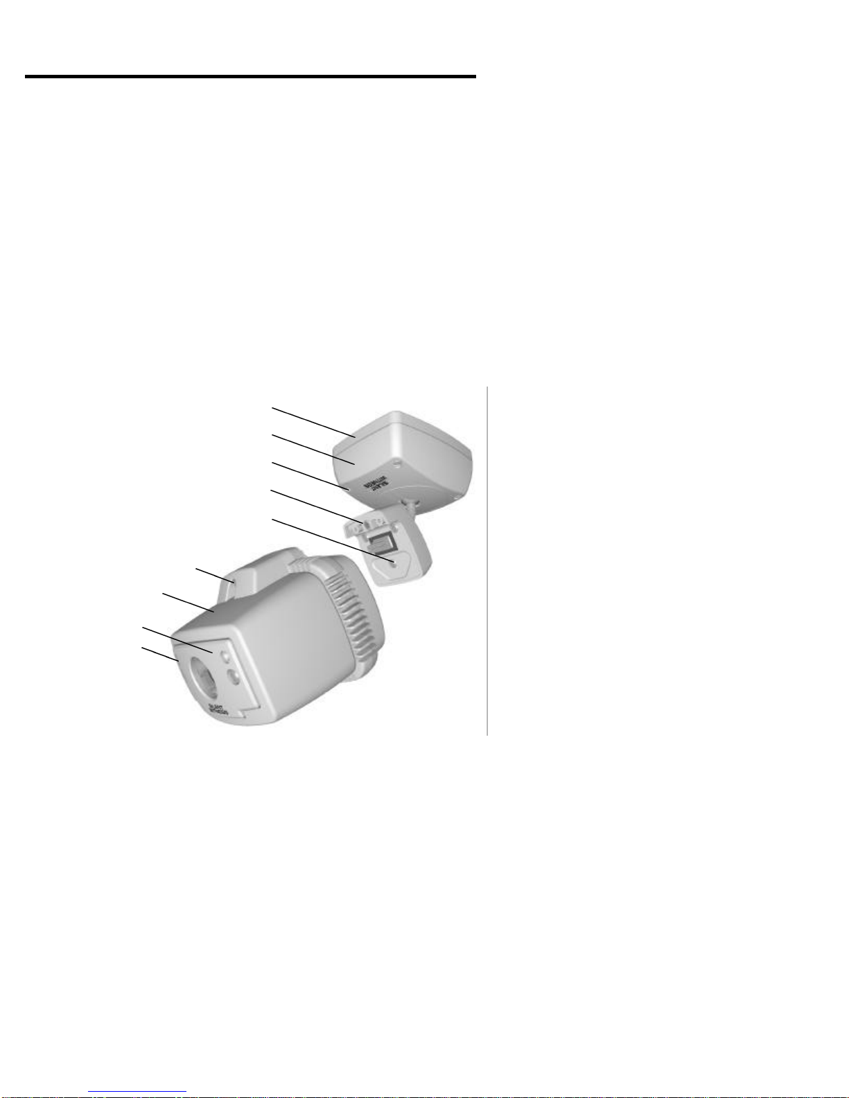
Mounting base
Mounting base cover
Cover locking screws (×4)
Connector block
Pivot arm locking screws (×3)
Camera retaining screw
Camera enclosure
Front panel light
Front panel

Installation - continued
11
4Use the security hex key to loosen (but not remove)
the three machine screws that lock the pivot arm ball
joint in the connector block.
5Plug the camera enclosure onto the connector block
and secure it in place with the #6-32×2" retaining
screw.
6Use the security hex key to loosen the two #6-32×½"
machine screws that secure the front panel of the
camera enclosure. Remove the front panel of the
camera enclosure.
7Plug a video playback cable (provided with the
SWC40) into the video connector on the front of the
camera. Plug the other end of the video playback
cable into the video input connector on a video
monitor.
8Turn on the power to the camera and the power to
the video monitor.
If you do not see a live picture on the video monitor, the
SWC40 is probably in playback mode. Press the ¢¢EXIT
button for longer than 3 seconds to exit playback mode.
9Adjust the position of the camera enclosure and the
pivot arm to the desired view on the video monitor.
10 Use the security hex key to tighten the four machine
screws that secure the cover to the mounting base to
lock the pivot arm ball joint in the mounting base.
11 Remove the camera enclosure from the connector
block. Use the security hex key to tighten the three
machine screws that lock the pivot arm ball joint in
the connector block.
12 Plug the camera enclosure onto the connector block
and secure it in place with the #6-32×2" retaining
screw.
Note:

Installation - continued
12
Adjusting Audio Sensitivity
The audio output signal is always available at the audio
output connector of the audio/video/power cable. The
audio signal is not recorded by the SWC40.
The audio sensitivity of SWC40 Series Cameras may
need to be increased in quiet locations or decreased in
noisy locations.
υTo adjust the audio sensitivity
1Use the security hex key provided in the SWC40
Installation Kit to loosen the two machine screws
that secure the front panel to the camera enclosure.
2Hold the front panel in place and monitor the audio
signal.
3Remove the front panel to adjust the small trimmer
located to the left of the microphone as shown on the
next page.
•Turn the trimmer clockwise to increase audio
sensitivity.
•Turn the trimmer counterclockwise to decrease
audio sensitivity.
The trimmer will be permanently damaged if it is forced
to turn too far.
4Repeat steps 2 and 3 until the audio sensitivity is
correctly set.
5Secure the front panel in place with the machine
screws.
Caution:
Installation - continued
13
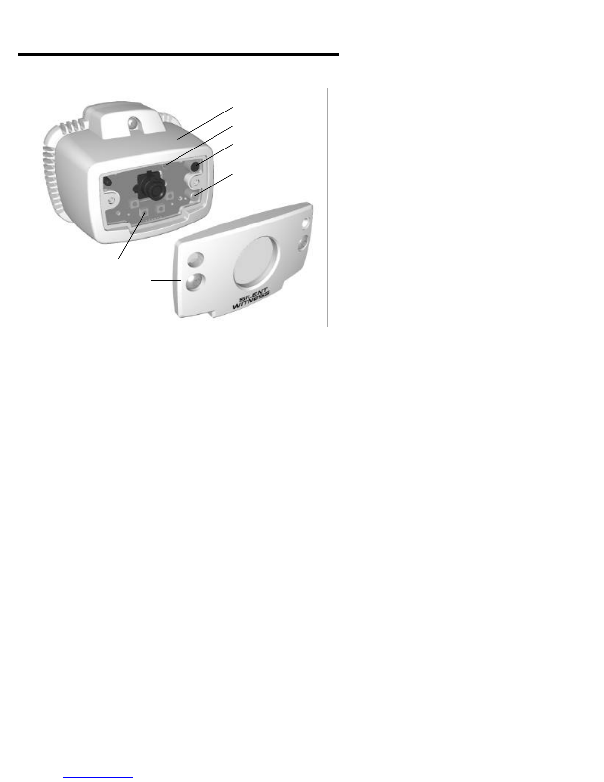
Camera enclosure
Audio sensitivity trimmer
Microphone
Front panel
EXIT button
Video connector

14
Recording
The SWC40 has a built in, programmable, digital video
recorder that can be triggered by an internal video
motion detector and/or by an external trigger signal.
The image quality, recording rate, recording duration,
and trigger source can be programmed from on-screen
menus (see the Programming section of this guide on
page 22 for details).
Recording Modes
The SWC40 recording cycle includes the following
modes of operation:
In disarmed mode, the SWC40 is waiting for an arming
signal from the handheld remote control or from the
external arming input signal. When an arming signal is
received, the SWC40 goes to arming mode.
In arming mode, the SWC40 ignores triggers from the
internal video motion detector and/or the external trigger
input signal for 60 seconds. When the arming delay
ends, the SWC40 goes to armed mode.
In armed mode, the SWC40 is waiting for a trigger from
the internal video motion detector and/or the external
trigger input signal. When a trigger occurs, the SWC40
goes to record mode.
In record mode, a sequence of digital images are
recorded for a programmed length of time. When the
recording sequence ends, the SWC40 returns to armed
mode.
Disarmed
Arming
Armed
Record

Recording - continued
15
While the SWC40 is disarmed, arming, armed, or
recording, a live video signal is output with a user
programmable time, date, and title overlay.
Turning power off while the SWC40 is arming, armed,
or recording will arm the SWC40 when power is
restored. Otherwise, the SWC40 is disarmed when
power is restored.
The light on the front panel of the SWC40 camera
enclosure flashes a unique pattern for each mode of
operation, as shown in the table below.
Front Panel Light Camera Mode
Red flash every
4seconds Disarmed
Double red flash every
4seconds Disarmed. At least one sequence was
recorded more than 30 seconds before the
camera was disarmed (see note below).
Red flash every second Arming
Continuous red Armed or recording
Continuous green Camera is too cold to operate. Wait for
camera to warm up to operating
temperature.
Off Camera is powered off, in playback or
program modes, or has failed.
If the only sequence recorded occurred 30 seconds or
less before disarming, it is assumed that the sequence
was triggered by the person who disarmed the camera.
The sequence will be recorded but the front panel light
will NOT double flash every four seconds.
Note:
Recording - continued
16
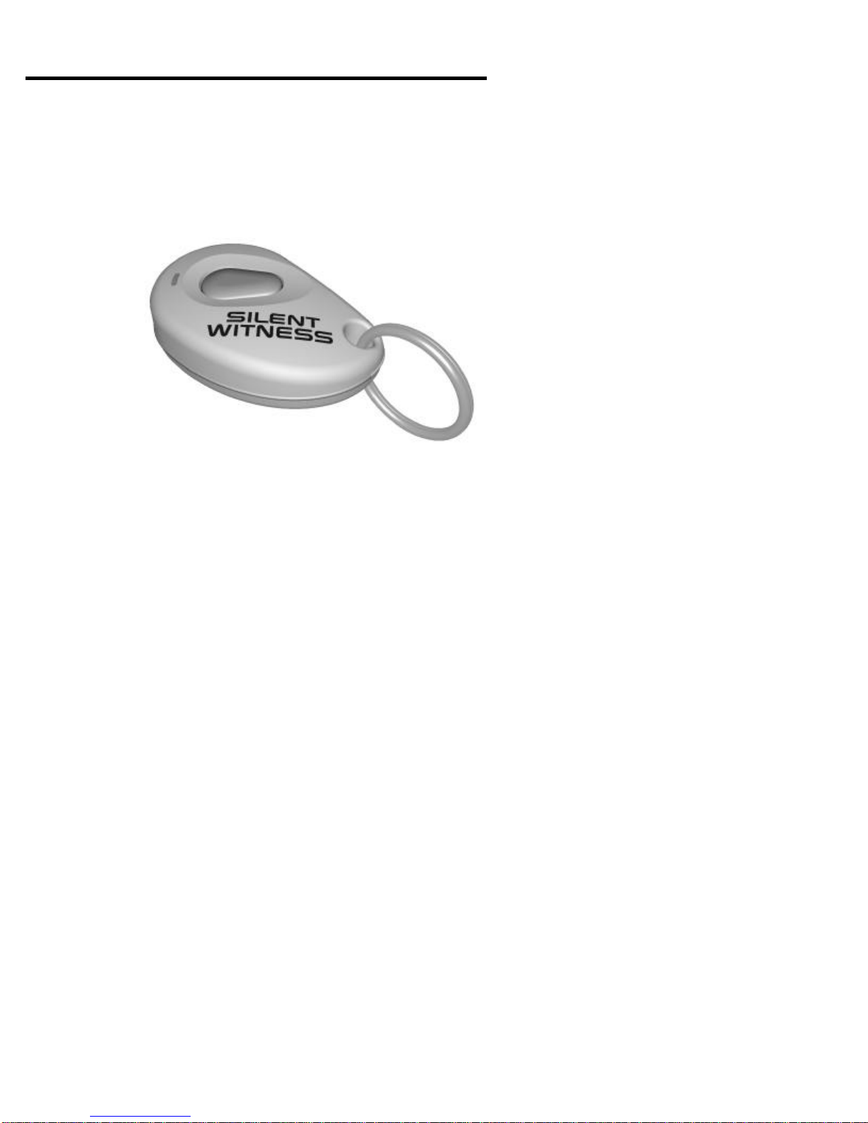
Using the Handheld Remote Control
The SWC40 can be armed or disarmed using a handheld
remote control that fits on a key ring. The radio signal
range of the remote control is at least 20 feet (6 meters)
if there are no walls or obstructions blocking the signal.
υTo arm the camera
qq While the SWC40 is disarmed, press the handheld
remote control button once to start the 60 second
arming delay.
qq While the SWC40 is disarmed, press the handheld
remote control button once, wait one second, then
press the remote control button a second time to
immediately arm the camera (no arming delay).
υTo disarm the camera
qq While the SWC40 is arming, armed, or recording,
press the handheld remote control button once to
disarm the camera.
or

Recording - continued
17
Using the Camera Buttons
The SWC40 can also be armed or disarmed using
buttons on the front or back of the camera enclosure.
υTo arm the camera
qq While the SWC40 is disarmed, press and hold the
ωωυυFORWARD and ττϖϖREVERSE buttons at the same
time for longer than 3 seconds to start the 60 second
arming delay.
υTo disarm the camera
qq While the SWC40 is arming, armed, or recording,
press and hold the ωωυυFORWARD and ττϖϖREVERSE
buttons at the same time for longer than 3 seconds to
disarm the camera.
ττϖϖREVERSE
ωωυυFORWARD
ττϖϖREVERSE
ωωυυFORWARD
BackFront

Recording - continued
18
This page intentionally left blank.
Table of contents
Other Silent Witness Security Camera manuals

Silent Witness
Silent Witness SW010 User manual

Silent Witness
Silent Witness MagnaView V28R User manual

Silent Witness
Silent Witness V25 ArmorDome User manual

Silent Witness
Silent Witness SW001 User manual

Silent Witness
Silent Witness Night Hawk SWX45 User manual

Silent Witness
Silent Witness SW021 User manual

Silent Witness
Silent Witness SWX80 User manual

Silent Witness
Silent Witness SW2200 User manual

Silent Witness
Silent Witness V60 Night Hawk User manual


