Silex technology Silex SX-500 User manual


Table of Con en s
1 OVERVIEW.............................................................................................................................1
2 DEVICE OPERATION ...........................................................................................................1
2.1 OPERATIONAL ENVIRONMENT ...............................................................................................................1
2.2 SEC RITY F NCTIONS........................................................................................................................2
3 PHYSICAL PORTS AND LOGICAL INTERFACES...............................................................3
3.1 PHYSICAL PORTS..............................................................................................................................3
3.2 LOGICAL PORTS...............................................................................................................................3
4 INSTALLATION AND USE.....................................................................................................4
4.1 REQ IRED CONFIG RATION..................................................................................................................5
4.2 INSTALLATION ..................................................................................................................................5
4.3 SE..............................................................................................................................................6
4.4 SELF TESTS....................................................................................................................................7
4.4.1 Power on Self Tests.............................................................................................................7
4.4.2 Conditional Self Tests..........................................................................................................8
4.4.3 Self Test Failure...................................................................................................................8
5 MAINTENANCE......................................................................................................................8
6 ELECTROMAGNETIC COMPATIBILITY...............................................................................8
Downloaded from Arrow.com.Downloaded from Arrow.com.Downloaded from Arrow.com.

1 OVERVIEW
The SX-500 is a multi-chip standalone cryptographic module designed by Silex Technology
America, Inc. to provide an encrypted wireless LAN connection for an attached client device.
The client device may attach to the SX-500 via a serial port or wired Ethernet port. Secure
LAN communication is provided by FIPS 140-2 compliant WPA2 (AES-CCMP) encryption
with manual key distribution (WPA-PSK) or IEEE 802.11i key exchange with a RADI S
server using EAP protocols such as EAP-TLS or PEAP. This document describes the
proper procedures for a user of the device to install and use the device.
This document describes the SX-500 hardware assembly, STA part number 132-00188-120
rev. B or rev. C with version 2.02 firmware and version 3.1 boot loader.
2 DEVICE OPERATION
2.1 Opera ional Environmen
The module is a stand alone device with operating firmware programmed in non-volatile
Flash memory. Operation of the device requires connection of a power source and interface
cables to the interface ports desired to be used. Operation of the device commences when
power is applied and the power up self test and initialization completes. Operation ceases
when power is removed.
The module contains a limited operational environment that is enforced via the firmware load
test using HMAC-SHA1. As such the cryptographic module only supports loading and
running of trusted code
SX-500 FIPS 140-2 User Guidance Manual 140-00188-230A
C pyright 2009 Silex Techn l gy America Inc. All rights reserved 1
Downloaded from Arrow.com.Downloaded from Arrow.com.Downloaded from Arrow.com.Downloaded from Arrow.com.

2.2 Securi y Func ions
The table below indicates the cryptographic algorithms provided by the module.
Algori hm Approved Algori hm Cer ifica e Number
AES - CBC Y #1138, #1139
AES - CCM Y #1140
RSA (sign/verify) Y #540
SHA-1 Y #1058, #1059
HMAC SHA-1 Y #647, #648
SP800-90 DRNG Y #19
MD5 N n/a
RC4 N n/a
HMAC-MD5 N n/a
MD4 N n/a
DES N n/a
Hardware NDRNG N n/a
In the FIPS approved mode, the module supports AES for encryption/decryption, RSA for
authentication and key transport, and HMAC SHA-1 and SHA-1 for message authentication.
The module supports the following non-Approved functions as allowable for use in the FIPS
mode of operation:
–non-deterministic hardware RNG (used for seeding the Approved SP800-90 DRBG in
FIPS mode)
–EAP-TLS (for key establishment in FIPS mode as per FIPS 140-2 IG 7.1)
–PEAP (for key establishment in FIPS mode as per FIPS 140-2 IG 7.1)
–802.11i KDF (for key establishment in FIPS mode as per FIPS 140-2 IG 7.2)
SX-500 FIPS 140-2 User Guidance Manual 140-00188-230A
C pyright 2009 Silex Techn l gy America Inc. All rights reserved 2
Downloaded from Arrow.com.Downloaded from Arrow.com.Downloaded from Arrow.com.Downloaded from Arrow.com.Downloaded from Arrow.com.

3 PHYSICAL PORTS AND LOGICAL INTERFACES
3.1 Physical Por s
The following physical ports are available on the unit.
Por Name Descrip ion
Power Jack for attachment of external power supply
Ethernet RJ-45 connector for attachment of Ethernet cable
Serial DB-9 connector for attachment of serial interface cable
Wireless RP-SMA connector for attachment of an external antenna
Button Momentary push button
LED Green, Yellow and Orange LEDs
3.2 Logical Por s
The SX-500 has logical interfaces for transfer of data and for configuration and control of the
unit. These logical interfaces may share a physical port. The application firmware in the SX-
500 separates and routes the data to the appropriate internal firmware task associated with
the logical interface. For network ports (Ethernet, Wireless) this separation is based on the
TCP or DP protocol port number. For the serial port, data or control/status mode is
controlled by specific protocol strings, only one mode is active at a time. Serial port
control/status mode is only available if the unit is explicitly configured to allow it. The
following table describes the logical interfaces of the unit when operating in a FIPS 140-2
approved mode.
FIPS-140-2 In erface Physical In erface Logical In erface
Data Input Serial Plaintext data for transmission to network
Ethernet Plaintext data for bridging to wireless network
Wireless Ciphertext data for Serial or Ethernet port
Data Output Serial Plaintext data received from wireless network
Ethernet Plaintext data received from wireless network
Wireless Ciphertext data from Serial or Ethernet port
Control Input Ethernet Control data for console task received via Telnet
Control data for web config task received via HTTP
SX-500 FIPS 140-2 User Guidance Manual 140-00188-230A
C pyright 2009 Silex Techn l gy America Inc. All rights reserved 3
Downloaded from Arrow.com.Downloaded from Arrow.com.Downloaded from Arrow.com.Downloaded from Arrow.com.Downloaded from Arrow.com.Downloaded from Arrow.com.

FIPS-140-2 In erface Physical In erface Logical In erface
Wireless Control data for console task received via Telnet
Control data for web config task received via HTTP
Button Invoke configuration/status function
Status Output Ethernet Plaintext Status response from console task via
Telnet
Plaintext Status response from web config via
HTTP
Wireless Status response from console task via Telnet
Status response from web config via HTTP
Serial Plaintext Status from button push
LEDs Indicate link and unit error status
Power Interface Power
Serial
When the module enters an error state, all Data Input and Data Output interfaces are
disabled. If an error state is encountered, the LED interface will indicate the error by blinking
for several seconds, and then the unit will reset. The unit will not send or receive any data
until the reset is complete.
The SX-500 performs cryptographic self tests during initialization after power up or a
firmware induced reset. ntil the self tests are complete, no data input or output interfaces
are active. If the self test fails, the unit will enter an error state.
The Data Output interfaces are logically disconnected from the processes that perform key
generation and zeroization. No key information is output through the Data Output interfaces
during key generation or zeroization.
4 INSTALLATION AND USE
Before the SX-500 may be used in the target environment, it must be properly configured by
a Cryptographic Officer with the necessary security parameters and network identification
values. Please refer to the Cryptographic ser Guidance Manual for details of this
procedure.
SX-500 FIPS 140-2 User Guidance Manual 140-00188-230A
C pyright 2009 Silex Techn l gy America Inc. All rights reserved 4
Downloaded from Arrow.com.Downloaded from Arrow.com.Downloaded from Arrow.com.Downloaded from Arrow.com.Downloaded from Arrow.com.Downloaded from Arrow.com.Downloaded from Arrow.com.
4.1 Required Configura ion
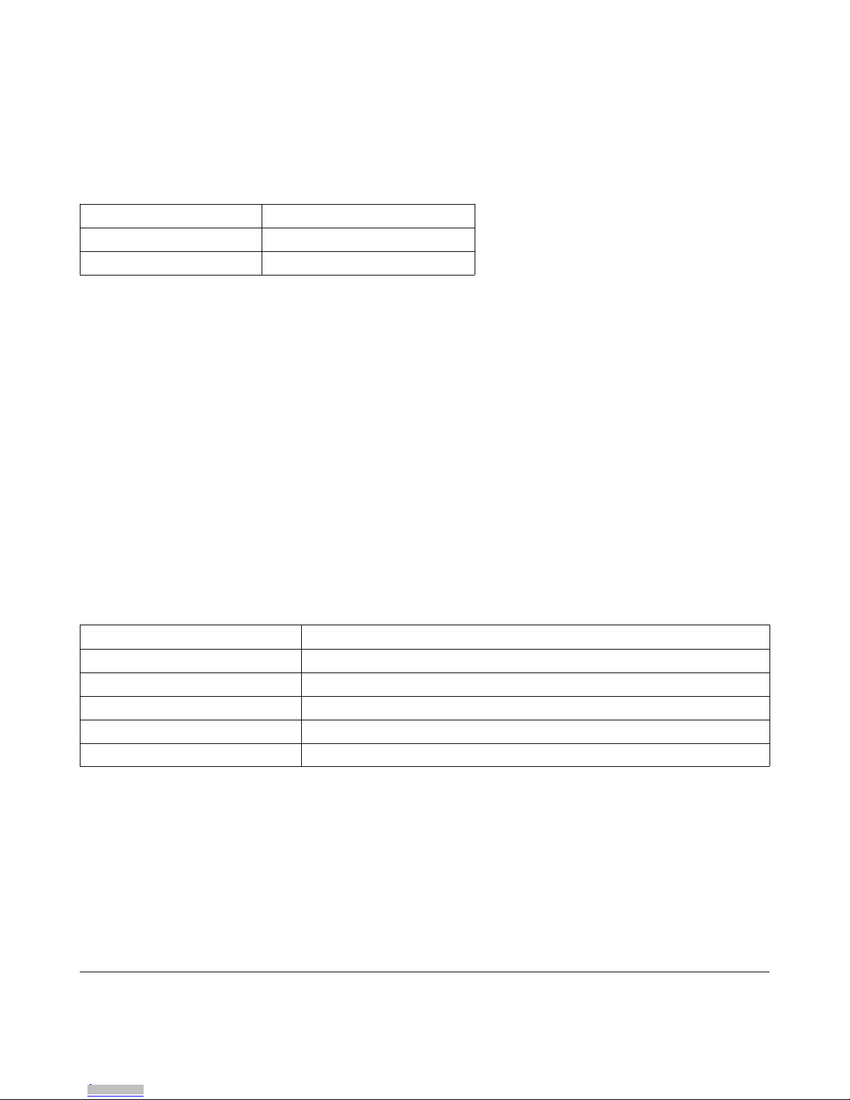
For the SX-500 to operate in FIPS 140-2 approved mode, the wireless security configuration
must be set as follows:
I em Required Se ing
Wireless Encryption Mode WPA2 (AES-CCMP)
Wireless Authentication PSK or TLS or PEAP or FAST
The Cryptographic Officer can verify these parameters are set properly through the console
or web control interfaces. Other parameters, such as the SSID of the Access Point to target,
must also be set, but depend on the specific operating environment.
The SX-500 allows o her securi y se ings for in eroperabili y in non FIPS 140
environmen s. However, use of he SX-500 wi h any se ings o her han hose
indica ed above is no FIPS 140-2 complian and is considered bypass opera ion.
There are wo ypes of bypass s a es possible wi h he module (non-approved modes).
The firs is o use any wireless encryp ion/au hen ica ion combina ion no specified
above as being FIPS 140-2 complian and hen rese he uni . The second is o
configure he uni o no be in E herne o Wireless mode, plug in a wired E herne
cable, and hen rese he uni .
In addition to the wireless security settings above, the following settings must be made for
operation in FIPS 140-2 mode:
I em Required Se ing
HTTPS Disabled (factory default)
S-Telnet Disabled (factory default)
TCP data service SSL Disabled (factory default)
Serial port console mode string N LL (disabled – factory default)
Serial port filter TRAP (factory default)
4.2 Ins alla ion
To install the device, it must be connected to the target device and power applied. A cable
should be attached between the target device and either the wired Ethernet port, or the serial
port as appropriate. The antenna should be attached to the SMA antenna connector for best
performance. The antenna should be positioned so that there are a minimum number of
obstacles (walls, filing cabinets, etc.) between the antenna and the target Access Point.
SX-500 FIPS 140-2 User Guidance Manual 140-00188-230A
C pyright 2009 Silex Techn l gy America Inc. All rights reserved 5
Downloaded from Arrow.com.Downloaded from Arrow.com.Downloaded from Arrow.com.Downloaded from Arrow.com.Downloaded from Arrow.com.Downloaded from Arrow.com.Downloaded from Arrow.com.Downloaded from Arrow.com.

Power must be supplied to the unit either via the power jack, using the Silex power adapter
(Silex PN 106-00024-51 or equivalent) or by providing +5V power on pin 9 of the serial port
DB-9 connector.
4.3 Use
Once properly configured by the Cryptographic Officer, use of the SX-500 is quite simple.
Simple enable the power supply to the unit (by plugging it in or throwing the appropriate
power switch). After a short initialization period, the SX-500 will be operational and ready to
secure wireless LAN communication to the attached device. When the unit connects to the
target Access Point (as configured by the Cryptographic Officer), the green status LED on
the unit will be lit. When the unit has been authenticated by the Access Point, and wireless
LAN communication is possible, the yellow status LED will be lit. In this state all wireless
LAN data communication will be encrypted using FIPS approved AES encryption for security
of the link.
If the green LED is blinking, it indicates the device is in a non FIPS 140-2 approved mode
(bypass). The LED will blink slowly when idle, and faster when there is data traffic on the
network link.
To terminate use of the device, remove power from it.
SX-500 FIPS 140-2 User Guidance Manual 140-00188-230A
C pyright 2009 Silex Techn l gy America Inc. All rights reserved 6
Downloaded from Arrow.com.Downloaded from Arrow.com.Downloaded from Arrow.com.Downloaded from Arrow.com.Downloaded from Arrow.com.Downloaded from Arrow.com.Downloaded from Arrow.com.Downloaded from Arrow.com.Downloaded from Arrow.com.

4.4 Self Tes s
4.4.1 Power on Self Tes s
The power on self test consists of a firmware integrity test, and known answer tests for the
cryptographic algorithm implementations.
The firmware integrity test is performed when the module is initialized after power-up or a soft
reset. A 32-bit checksum is computed on the stored firmware image, and compared to the
expected value. The firmware integrity test passes if and only if the computed checksum
matches the value previously stored with the firmware image. If the integrity test fails the
firmware will not be allowed to execute.
The configuration memory integrity test reads the configuration information from the flash
storage, computes a 16 bit checksum, and compares it to the stored value in the
configuration. If the values do not match, the configuration memory is zeroized and reset to
the factory default values.
The module also performs the known answer tests on the following algorithms:
AES CBC & CCM
RSA
DRNG
SHA-1
HMAC SHA-1
MD5
TLS-PRF
SX-500 FIPS 140-2 User Guidance Manual 140-00188-230A
C pyright 2009 Silex Techn l gy America Inc. All rights reserved 7
Downloaded from Arrow.com.Downloaded from Arrow.com.Downloaded from Arrow.com.Downloaded from Arrow.com.Downloaded from Arrow.com.Downloaded from Arrow.com.Downloaded from Arrow.com.Downloaded from Arrow.com.Downloaded from Arrow.com.Downloaded from Arrow.com.

4.4.2 Condi ional Self Tes s
The module performs the following conditional self tests:
Algori hm Procedure
Approved DRBG Continuous test
Non-approved hardware RNG Continuous test
Wireless link encryption bypass First packet encryption verification
Firmware load Firmware keyed hash verified after download and
before flash firmware image is modified.
Encryption algorithms Known answer tests from the previous section when
directed by the Cryptographic officer
RSA key generation Pairwise consistency test after key generated.
4.4.3 Self Tes Failure
If one of the unit self tests detects an error, the unit enters an error state. This will be
indicated on the exterior of the unit by the continued blinking of the orange status LED. After
displaying the error condition for several seconds, the unit will usually self reset to attempt to
clear the condition. If the unit does not self reset for some reason, you may reset the device
by removing and the reapplying power. If the error recurs repeatedly, please notify the
appropriate people in your organization for diagnosis, repair or replacement.
5 MAINTENANCE
There is no user maintenance involved in the use of the SX-500. If a defect is observed in
the operation of the device, it should be referred to security management personnel for
replacement or repair.
6 ELECTROMAGNETIC COMPATIBILITY
The module conforms to FCC Regulations Part 15, Class B. The module radio is certified for
intentional emissions with FCC ID N6C-SX10WG.
SX-500 FIPS 140-2 User Guidance Manual 140-00188-230A
C pyright 2009 Silex Techn l gy America Inc. All rights reserved 8
Downloaded from Arrow.com.Downloaded from Arrow.com.Downloaded from Arrow.com.Downloaded from Arrow.com.Downloaded from Arrow.com.Downloaded from Arrow.com.Downloaded from Arrow.com.Downloaded from Arrow.com.Downloaded from Arrow.com.Downloaded from Arrow.com.Downloaded from Arrow.com.
Other manuals for Silex SX-500
1
Table of contents
Other Silex technology Control Unit manuals


Popular Control Unit manuals by other brands


RADEMACHER
RADEMACHER ReWiSo Installation and operating instructions

CapstanAG
CapstanAG PinPoint installation instructions

Bender
Bender LINETRAXX MRCDB423 manual

ProSoft Technology
ProSoft Technology ILX34-MBS485 user manual

Emerson
Emerson Kunkle Valve Series Installation and operating instructions

Dynacord
Dynacord PRO MATRIX SYSTEM DEM 314 owner's manual


