SilverLeaf Electronics RV-C OMNISCOPE User manual

RV-C OmniScope Manual
Technician Manual
v2.3
Page 1 10/31/17

RV-C OmniScope Manual
Table of Contents
Installation .......................................................................................................................................... 3
File Installation....................................................................................................................................3
Driver and Key Installation..................................................................................................................3
Updates And Scripts...........................................................................................................................4
Introduction to RV-C ......................................................................................................................... 5
Starting OmniScope ......................................................................................................................... 6
Checking The Adapter........................................................................................................................6
unning the OmniScope Program......................................................................................................6
The eset Button................................................................................................................................7
Quitting................................................................................................................................................7
Running Modules ..............................................................................................................................
unning Scripts...................................................................................................................................8
Specialty Modules and how to use them ........................................................................................ 9
V-C Sniffer........................................................................................................................................9
Downloading Tools.............................................................................................................................9
Universal Diagnostic Module ...........................................................................................................10
Configuration Tools...........................................................................................................................11
V-C Terminal..................................................................................................................................11
Warranty............................................................................................................................................12
Page 2 10/31/17

RV-C OmniScope Manual
Installation
Before File installation, see the important note on pg.6 under the heading: “Starting Omniscope.”
File Installation
OmniScope does not require a special installation program. The files should just e copied to a
folder named “Omniscope.” Other folders will e added to this over time such as additional
“Scripts”, “Clones” and “BINs” --for creating a 'copy' of a units' settings for use later and for
software (binary) files you download when updating a Box or screened-unit**.
Method A:
From CD: Copy the “Omniscope” folder to C:\ --Not to your desktop or “My Downloads” --When
you need phone help in the future, it will e very difficult if the system is not in the right place.
Method B:
Install from the internet y downloading the files directly to the folder “C:\Omniscope.” This
internet distri ution is compressed. What happens when clicking on the link depends on your
Windows version and rowser.
1. If it pops up a ox giving some options, choose the default of “Open with Explorer” then wait
a it for the download to start and for the next step. Next a window opens showing a single,
decompressed, file folder. Copy that folder to your C:\ drive. You're mostly done. --or--
2. If, when clicking on the download link, the download starts ut minimizes, its likely dropping
it automatically in your Downloads portion of your 'Documents.' Your rowser may have a
link at the ottom of the window showing its progress and link. Click that link to e taken to
the compressed folder.
Click on that file “Omniscope_CD_Image(date).zip” either with a <right click> and
selecting Extract All or Select it and press the Top Bar menu item “Extract.” Choose a
location of “C:\” (or “Windows C:\”), select “Extract All” as a folder named “Omniscope.”
The goal is to have an Omniscope folder here: C:\Omniscope
Finally, create a “shortcut” for OmniScope from the C:\Omniscope folder.
For the Desktop:
<Right-click> on the OmniScope Shortcut (located now in C:\Omniscope) and select <Create
Shortcut>
Next, Copy the shortcut to your desktop. You may rename it.
For your Task Bar:
<Right-click> on the OmniScope Shortcut and select <Pin To Task Bar> This is a great way to
always have it availa le, without having to minimize or hunt around.
** “Screened Unit”: Any Silverleaf product with display ie Glass Dash, HMS360/365, VMS440...
Driver and Key Installation
Before you can use OmniScope you must first install the USB driver for the adapter. Plug the
USB-to-RV-C adapter into the USB port of your laptop. Within a few seconds the computer should
detect the adapter and start the “Add New Hardware” wizard. The wizard will prompt you for the
location of the driver file. Click on the Browse utton and point the wizard to C:\OmniScope, or if
you are installing from the CD you can use the driver files on the CD.
This may also e accomplished y running the App “Install_Drivers.exe” Reboot to finish.
Page 3 10/31/17

RV-C OmniScope Manual
Once rebooted you're ready for the 'Key' entry. Note: Your key, a 26-character code, may have
een pre-loaded with your included-CD, if so, no intervention is required. If it wasn't included—or
if you've just downloaded the latest distro or are may e starting over, the 'key' will need to e
added manually. You'll know the key y its length and jum le of letters, sym ols and num ers; its
on the la el located on the little lack “Apox” ox—the one with the USB cord.
To Add a key manually: Open the Omniscope program. If you're greeted with the error “No
Adapter Found” return to the previous steps for installing the driver. Call us if you get stuck here.
Otherwise, click on <Add Key> (top right corner) and type in the key. Type it in exactly then click
<Add> then <Done>. Clicking <Done> first means you'll e re-entering the key :-/
The keys are all ased on the serial num er of the USB-to-RV-C adapter. If your shop is using
multiple adapters, you can enter keys for all the different adapters on all the different computers so
you don't have to worry a out which computer is eing used with which adapter. The keys are
stored in a file called “key.txt” which can e shared among all the computers in the shop. Thus
you can install OmniScope and its modules on any num er of computers, as long as you have at
least one valid adapter and the proper code.
Lost your 'sticker' and don't know the code? Call us; we'll recreate it for you while on the phone.
Updates And Scripts
SilverLeaf deli erately designed OmniScope to make it as simple as possi le to update the
system and download new modules. To update any of the modules, scripts, or files, simply
download or copy them into the C:\Omniscope folder you created. There are no other installation
programs to run. Drop modules into the main Omniscope folder.
Manually drop Scripts into a folder this way:
C:\Omniscope
...Coach (Fleetwood)
… … year (2013)
...TM/VMS unit (ex. TM250)
...Special Purpose (Tests) or unique script.
This way the Coach scripts are easy to find. Also,
individual units' scripts and those for testing may e
found quickly.
Its here where you'll also save a “Clone” for when you
want to create a script to duplicate settings for a very
specific coach or unit. This is also helpful for when, as
in a HMS unit, the settings are tailored y the owner ut
must e the same at each Control Panel.
The ones shown, at right, are typical. More a out this later on. First, an Introduction and
Overview...
Page 4 10/31/17

RV-C OmniScope Manual
Introduction to RV-C
The network or 'Can Bus' for RVs is called RV-C. It's a standard for RV appliances to talk to
share information, provide diagnostic data, control and e controlled. It is a “peer” network,
meaning every appliance ( lack ox/ display), or “node”, is equal in the eyes of the network. A
typical network will consist of at least one or two control panels, one multipurpose controller, and
any num er of appliances such as inverters, generators, and slide rooms. All the data is shared
digitally using a single pair of wires.
These two wires form a “ us”, connecting each node. The “trunk” of the us may e quite long,
ut the “drops” (lines from trunk to node) are limited to no more than six feet in length. At each
end of the trunk is a 120 ohm resistor connecting the two data lines. These resistors a sor any
“ringing” on the us.
Each factory RV-
C-equipped coach
should include a
nine-pin circular
connector, located
either under the dash
or in the utility ay.
This connector
allows the service
tool to tap into the
network and ecome
another node in the
system.
In the event one
wasn't added, a 'T' or
bus-tap must be
used to 'tap in.'
Helpful Hint: When you do an V-C conversion, include one or two of these sockets to make
installation and maintenance easier. You will likely see this coach again; make it easier now.
Once connected, the service tool can send commands and ask for data from every node in the
system. At this point, you may want to skip directly to “Starting Omniscope.” ...otherwise...
Nodes send commands and messages in small packets. Each packet can contain several
pieces of data - for example, temperature, current, and voltage. Each packet is identified y a
Parameter Group Num er, or PGN, and you can determine the contents of the packet y looking
up the PGN in the RV-C documentation. Some PGNs are unique to a certain type of product - e.g.
Slide Rooms use a PGN called SLIDE_STATUS. Some PGNs are common to all products - e.g.
the PRODUCT_ID PGN is universal to all RV-C devices. For the most part you don't need to know
the details of the PGNs to trou leshoot a network. It's the software's jo to parse these packets of
data into meaningful values on your screen.
One of the most important PGNs, which is common to all RV-C nodes, is the DM1, or Diagnostic
Message. This message is sent y all nodes to communicate general operating status and
whether any pro lems have een detected.
Each node has a Source Address, which is used simply to make sure no two nodes talk at the
exact same time. But a node may have more than one function - e.g. an inverter/charger is oth
an Inverter and a Charger. These multifunction nodes may display multiple DM1 messages. For
example, the Charger may e Off, while the Inverter is On and displaying a Low DC Voltage
warning. Each DM1 is distinguished y a DSA, or Default Source Address, which shows which
function is eing descri ed in the message.
Page 10/31/17

RV-C OmniScope Manual
Starting OmniScope
This is an advanced tool capa le of helping the technician trou leshoot, service and configure
RV-C ased equipment. Make sure you understand the potential outcome efore making changes
with the Omniscope.
Plug in the USB-to-RV-C adapter into the PCs' USB port. When starting the program you may
see “Tool Not Responding” message. This can e caused merely y unplugging the adapter
unexpectedly, and is not necessarily a real pro lem as the program often can find the adapter on a
second try. If it can't, the program will a ort. Make sure the adapter is plugged in and try again.
Checking The Adapter
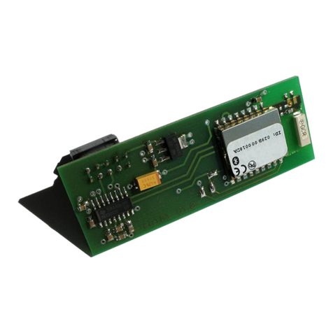
The adapter has four LEDs, two green, two red. When you first plug it in you should see just
one green LED flashing. If not, then the unit is not receiving 12Vdc power - check the ca le and
the port for pro lems.
Once the OmniScope program has initialized the adapter, rapid flashing will stop. Instead the
LEDs will start flashing with each data packet that it sends and receives on the data us. If you
have not yet plugged the adapter into the V diagnostic port there should be an initial few flashes
and not much else. When you plug it into the RV you should start seeing lots of activity.
You can verify this y clicking the Statistics utton in the
OmniScope program. This should ring up a ox showing
two items. The Tool ID is an eight-digit serial num er for the
adapter. Packets Received is the num er of packets seen so
far on the network. This num er should e constantly
increasing. If not, exit the program and start again just to e
sure the pro lem wasn't the tool initialization. If it still doesn't
work, you must start trou leshooting the physical wiring.
unning the OmniScope Program
OmniScope itself is a very simple program. It merely provides a general overview of the status
of the nodes on the network, and it provides a way to run other programs called “modules”. It's
the modules that do most of the real work - OmniScope itself is simply a starting point.
The OmniScope screen shows
three oxes. On the left is the
“Device List” - a list of every
“device” that has een detected.
Keep in mind that one node may
include several functions - each
function will show up as a different
device.
For each device OmniScope lists
the DSA, or Default Source
Address. This code merely
identifies the function of the device
- e.g. generator or inverter. Next it
lists the general operating status,
“On” or “Off”, and “Active” or
“Inactive”. For example, the
charger may e “On” ut “Inactive”
if no AC power is availa le for charging. The status may e highlighted in red or yellow if some
sort of pro lem is eing reported y the device.
The Device List (left side) will always include at least one item: the Service Tool itself.
Page 6 10/31/17

RV-C OmniScope Manual
To the right of the Device List is a Details ox. If you click on any device, the Details ox will
provide additional information on that item. It will show the actual Source Address of the device,
and more importantly it will show whatever Product Identification information the device will
provide. This may include manufacturer, model, and serial num er.
In the lower right is the Module List. This ox shows all the modules availa le as identified in
your Omniscope directory--and that might apply to that particular device. For example, clicking on
a Control Panel a SilverLeaf HMS365 control panel may present at the right side with such
modules as the Universal Diagnostic Device, V-C Terminal and the HMS360/365 Configuration
Tool. Clicking on an Genstart Controller (TM102) would ring up a different list of modules though
would still include an RV-C Terminal. Many tools are universal and very useful.
The eset Button
Clicking this utton will clear out the Device List and cause the program to start over again. This
is occasionally useful when disconnecting and reconnecting nodes, and when switching RVs.
Quitting
To quit, click the “Done” utton. However, the utton will not e accessi le ( 'greyed out' ) if
there are any modules still open. You must exit all other modules efore OmniScope will let you
shut it down. In the event—though rare—the remaining open module is hidden or can't be
closed, use the eyboard shortcut: Alt+F4 to close the process “OmniScope.exe” Restart
the Omniscope program and continue otherwise normally.
Running Modules
When you select a device from the
Device List, the Module List will show all
the modules that are installed on the
computer that are relevant to that device.
Dou le-click on any module, or select a
module and click on the “Run Selected
Module” utton.
Modules can e either scripts or full-
fledged programs. A program can have
almost any conceiva le purpose, and
each such program should have its own
instructions. The only limitation placed on
a program module is that the program
must e shut down efore you shut down
OmniScope. You can run more than one program at a time, and simply Alt-Ta or click the task
ar to switch etween different program modules.
If the module you need is not listed in the Module List, make sure the desired target device is
selected in the Device List. Then click on the “Run Module Not Listed Here”. This will ring up a
standard Windows File Selection dialog, and you can select the desired program (“.exe”) or script
(“.scp”). If you do not select a device efore starting the program or script, the module may not
run properly.
Page 7 10/31/17

RV-C OmniScope Manual
unning Scripts
A script may act like a devices' settings cri -sheet
or a mini-utility though it's not really an independent
program. Only one script can e run at a time, and
running a script does not open a new, separate
program. A script is a set of instructions to e
processed y OmniScope, typically the instructions
are RV-C commands to configure or test devices on
the network.
Simple scripts often run automatically, with little or
no intervention from the user. The script will start y
opening the Script Execution window. The top left
ox in this window provides information on the status
of the script execution. The script writer may include
various messages to provide feed ack for the user.
The script may include pauses, where the script will
wait for you to accomplish something and/or click a utton, enter a term or name or just hit 'Enter'
after a message is displayed. The A ort utton will end the script. The Continue utton will cause
the script to resume processing. While the script is running you can click A ort to stop the script
mid-stream.
Some scripts may include commands that require a specific response from the target device. In
this case you may see the Retry utton activate, meaning that the device has not responded as
expected and you have the option of trying the command again. Clicking on Continue will cause
the command to e skipped.
When the script is complete click on Close to close
the window and return to the main OmniScope
screen. Clicking on Print will print the contents of the
status window to the default printer.
Some scripts require more intervention from the
technician. Scripts can include menus. For example,
a configuration script for a certain model of RV may
require you to choose various options such as the
model of generator or the floor plan of the RV.
Scripts can also feature displays of live network
data. The ox at the ottom of the Script Execution
ox is the “Monitor List”. Scripts may put data items
in that ox, and the data items will continuously
update with the latest values that appear on the
network. Two num ers will appear next to the name
of the data item. The num er in the middle is the
current value. This can e “N/D”, or “No Data”, meaning that the data item has not een detected
on the network. It can also e “Err”, meaning that the device sending the datum is registering
some pro lem with the data item.
The num er on the right is the num er of times the datum has een seen on the network.
Normally this should continuously count up. The speed depends on the type of data, and can vary
from ten times per second to once every five seconds. In some cases the data is only provided on
an “as needed” asis.
The Monitor List can also include lines with no num ers. These lines are actually “ uttons” than
can e dou le-clicked to trigger specific commands. The effect depends on the intentions of the
script-writer. This technique is often used to provide a way to test various system functions, such
Page 8 10/31/17

RV-C OmniScope Manual
as starting the generator or leveling the RV.
A note on 'BatteryTest_v1_1.scp' This tool is
used to load-test a attery ank, revealing its actual
Amp-Hour capacity. Like other modules, its opened
y pressing the utton “Run Module Not Listed Here”
then navigating to the c:\omniscope\scripts\service
tests folder. Give the file a couple clicks in order to
start or initiate it. Its important to note that this is not
intended to e a comprehensive systems or inverter
test, just attery capacity. Before the test egins, the
secondary inverter needs to e, in fact, manually
disa led. When the script prompts the tech to enter
Script Parameters, this may include the Coach VIN/
SN or client; just something to make the file name
unique.
When finished, it will a printa le/ exporta le text
with complete test results. Afterwards, unplug any 'loads' added—such as a space heater or
anything plugged in just for this test.
Special Scripts: Should you find yourself in need of a special testing 'program' –such as the
Capacity/ Amp-Hour test, give us a call and explain how it should work. We may e a le to devise
such a tool.
The details of writing scripts is eyond the scope of this manual.
Specialty Modules and how to use them
There's a collection of tools here which every tech will find indispensa le. These Tools/ Modules
are in a constant cycle of review for improvement. As such, expect to see these updated
regularly. For example:
“RV-C Sniffer” See whats eing roadcast; voltages, charge rate, temperatures, valve
status...everything. Handy after a repair to check your work. Note: Has a Snapshot feature!
“Downloading Tools” Only used for dropping new software onto Silverleaf devices.
“Universal Diagnostics Device (module)” will display current errors and great for trou leshooting.
“RV-C Terminal” is used to send out commands and receive, essentially, hidden information
such as a log file. With this you can dig into the specifics of a device or status.
“Configuration Tool” -Need to change tank monitors or Inverter type? Start here. Most every
device has a Config Tool and can often e used to 're-script' or clone a ox.
V-C Sniffer
This presents real-time traffic as 'sniffed' off the RV-C us. It will also give the num er of each
message, allowing the viewer to see a struggling of faulty device. It also reveals any errors
currently roadcasted and includes the a ility to take a (text file) snapshot.
Downloading Tools
These are Software Programming specific and not usa le for general use. With practice and
experience one may order additional ca ling and software to program our devices. This, however,
is not for the average tech as there's a significant learning curve, even for the rightest. If you feel
your usiness would enefit from eing a le to fully and completely service our equipment, give a
call so that we may move forward with you.
Page 9 10/31/17

RV-C OmniScope Manual
Universal Diagnostic Module
The Universal Diagnostic Module can e used to
trou leshoot any RV-C device, regardless of the
make or manufacturer. All devices that are fully
RV-C compliant provide asic trou leshooting
information that this module can display and
interpret.
It is important to select the proper target device
efore starting this program. The module will
provide information only for the selected device.
The module displays the Source Address for the
target device, along with the Device Type (or
DSA). The Device Type indicates generally what
type of product the module is looking at. Note that
sometimes a product may include several different
devices. For example, a generator may include a
“Generator” (DSA 64) and a “Genstart Controller” (DSA 65). One of these devices may e
malfunctioning while the other is functioning fine. Or, one may have a pro lem linked to the other.
The module also displays the full Product Identification. This is a long string of letters and
num ers separated y asterisks, and indicates the manufacturer, product model, and may include
serial num ers as well. The details are up to each manufacturer.
The main window shows the diagnostic information, as provided y the device in the DM1
diagnostic message. The first three values, shown in rackets, shows the general status of the
device. First, whether the device is On or Off. Second, whether it is Active or Inactive. Third,
whether the device is in a “Yellow” or a “Red” fault condition.
The distinction etween On/Off and Active/Inactive varies among devices, ut most devices are
either Off, On and Inactive, or On and Active. On and Active means it is fulfilling its designed
purpose at this moment. On and Inactive means it is not producing anything at the moment, ut it
is prepared to do so at any appropriate moment - it is “standing y”. And Off means it will not do
anything without some intervention (usually, ut not always, from the user). Note that an item that
is Off likely still has power - otherwise it couldn't tell the network that it was off.
Generally “Yellow” faults are situations which can e remedied with only asic intervention, or
have negligi le effect on the operation of the device. A typical “Yellow” fault is low attery levels
for an inverter. “Red” conditions are more serious, and generally require attention from a
technician. These guidelines are su jective, of course, and manufacturers may interpret them
differently.
The next item displayed is a num er called the SPN, or “Suspect Parameter”. This num er has
two different forms, and the module shows oth forms. In the raw form the SPN is just a num er -
in the example a ove it is 2056. In the parsed form it is a series of three num ers - in the example
those num ers are 1, 1, and 0.
The interpretation of these num ers depends on the product. Most manufacturers provide a
ta le of the SPNs for their device, and that ta le will indicate the proper form for that device. The
distinction relies on whether the device is designed to allow multiple “instances” on the network.
The parsed form allows the ta le to show which specific device the fault applies to. The raw form
is used for products that can't have more than one installation on the RV.
Regardless of the form, the purpose of the SPN is the same. It identifies what component of the
device is malfunctioning. For example, in a generator the SPN might refer to the oil pressure or
tachometer. In a slide room the same SPN might refer to a proximity switch. Every different
device has its own list of potential SPNs.
The last num er (1, in our example), is the Failure Mode, or FMI. This num er is universal
Page 10 10/31/17

RV-C OmniScope Manual
among all devices, and identifies the general nature of how the SPN is ad. For example, an FMI
of 1 means “Below Normal Operating Range”, which would e a serious fault if the SPN is Oil
Pressure.
Fortunately, the module automatically looks all this data up in its own ta les, and provides the
interpretation on the next line. This interpretation is general to all manufacturers, so it will not
necessarily use the exact same terms as the manufacturer's documentation.
Normally the diagnostic information is sent automatically. If the device is not responding
properly, clicking on the Poll utton will request updated information from the device.
Configuration Tools
Warning:
Most configuration tools allow the tech ' ack door' access to functions and settings deemed too
specialized or dangerous for the casual user-owner to manage. These range from attery charge-
ridge and GenStart to Tank monitoring, heater and urner controls to network addressing. Each
of these may operate in real-time and a mistake or ' ad' setting has the potential to create havoc
at est, confusion for other techs and damage to the equipment and people at worst. Do not
change a setting unless you are sure of an appropriate, measura le outcome.
That said, the various configuration tools are set up uniquely, depending on the equipment they
modify or manage. Many contain an option to “Save for Cloning”. Think of this as a way to 'fall-
ack' to prior settings or migrate the setup on a given Silverleaf ox to its replacement or another
coach. This is common when like-coaches are availa le for trou leshooting; a given unit in a
known-good coach may e cloned and that newly created (txt) file can e used to overwrite a unit
with known or suspected ad settings. Use this tool often, save the setting this way efore
trou leshooting. Plan-ahead for success.
V-C Terminal
This module is used to send messages and receive information such as a log or “records” file.
Typing help on the command line will ring up a list of terms you can then use. Here's the most
used and useful, along with some pointers:
all = display CAN status
adc = display analog counts
actinv = display active inverter
att = display attery status ( Its just a snapshot )
can = display CAN status
c ridge = display charge ridge status
charger = display charger status
clock = display real-time clock
dev = display device list
erase = clear diagnostic messages **WARNING** This deletes the TM102 log file! <--
exec = display executive status
ffmem = initialize NVRAM
flash = display flash status
gen = display genstart status
io = display I/O status
j1939 = display J1939 parsing info
log = display diagnostic records. log -50 = 50 records. Don't type the word y itself !
mem = display memory size
Page 11 10/31/17

RV-C OmniScope Manual
nrec = display num er of diagnostic records Usually thousands long, Use this with log
nvram = display NVRAM content
onan = display onan status
out ack = display out ack status
parse = parse RV-C message
peek = display memory contents
port = display I/O port status
reset = reset NVRAM to factory defaults
send = send RV-C message
ser = display serial status
surge = display surgeguard status
tank = display tank status
therm = display thermometer status ( If none are connected, expect an empty space )
ver = display TM102 version
? or help = display this help
Warranty
THIS WARRANTY IS EXPRESSLY LIMITED TO VERIFIABLE RETAIL BUYERS OF SILVERLEAF
ELECTRONICS OMNISCOPE and OMNITOOLS.
SilverLeaf Electronics Inc. Omniscope is warranted against defects in materials and workmanship for one year (12
months) from date of delivery. You, the owner, shall e responsi le for and must prepay any shipping expense for
return of the Product. This warranty does not cover any Omniscope tool that has een a used, altered, used for a
purpose other than that for which it was intended, or used in a manner inconsistent with instructions regarding use. The
sole and exclusive remedy for any Omniscope tool found to e defective is repair or replacement, the option of
Silverleaf. In no event shall Silverleaf e lia le for any direct, indirect, special, incidental or consequential damages
(including lost profit) whether ased on warranty, contract, tort or any other legal theory. The existence of defect or
misuse shall e determined y Silverleaf Electronics Inc. in accordance with procedures esta lished y Silverleaf
Electronics Inc. No one is authorized to make any statement or representation altering the terms of this warranty.
INDEMNIFICATION
Purchaser agrees to indemnify, defend, and hold Silverleaf Electronics Inc. and its personnel harmless from any
claim arising out of or related to the Product or its use, installation, or service.
EXCLUSION OF CONSEQUENTIAL, INCIDENTAL, AND OTHER DAMAGES
Silverleaf Electronics Inc. Shall not e lia le for any incidental or consequential damages for reach of any warranty,
whether resulting from the use, misuse, or ina ility to use the product or from defects in the product or from the
negligence or other tort of Silverleaf Electronics Inc.. This exclusion covers, without limitation, damages for loss of use,
revenue or profit, cost of capital, cost of su stitute equipment, additional costs incurred y purchaser, and claims y
purchaser’s customers or other third parties.
SilverLeaf Electronics, Inc.
2490 Ferry St. SW
Albany, OR 97322
Worldwide: ( 41) 967-8111
Toll Free in US: (888) 741-02 9
w w w . s i l v e r l e a f e l e c t r o n i c s . c o m
Page 12 10/31/17
Table of contents
