AZZA 845S Series User manual

The
AZZA
845S MAINBOARD SERIES Page 1
845S Mainboard Series
845S Mainboard Series845S Mainboard Series
845S Mainboard Series
User’s Manual
User’s ManualUser’s Manual
User’s Manual
SOCKET 478 SDR ATX Mainboard
845S
845S845S
845S-
--
-AV
AVAV
AV
845S
845S845S
845S-
--
-AD
ADAD
AD
Version 1.0
UM-845S-AVD-E1
Rev 1.1V
Creation Date: 19 October 2001

The
AZZA
845S MAINBOARD SERIES
Page 2
Copyright
This publication contains information that is protected by copyright. No part of it
may be reproduced in any form or by any means or used to make any transforma-
tion adaptation without prior written permission from the copyright holders. This
publication is provided for informational purposes only. The manufacturer makes
no representations or warranties with respect to the contents or use of this man-
ual and specifically disclaims any express or implied warranties of merchantability
or fitness for any particular purpose. The user will assume the entire risk of the
use or the results of the use of this document. The manufacturer reserves the
right to revise this publication and make changes to its contents at any time, with-
out prior notice.
2001. All Rights Reserved.
Trademarks
Trademarks
Trademarks
Microsoft®, MS-DOS®, WindowsTM, Windows® 95 and Windows® 98 are regis-
tered trademarks of Microsoft Corporation. P4TM is a registered trademark of Intel
corporation. Award is the registered trademark of Award Software, Inc. Other
trademarks and registered trademarks of products appearing in this publication
are the properties of their respective holders.
Package Checklist
Package Checklist
Package Checklist
This package contains the following items:
•Mainboard
•Users manual
•One IDE cable
•One 34-pin floppy disk drive cable
•One Driver Utility CD
If any of these items are damaged or missing, please contact your dealer or sales
representative for assistance.
Technical Support
Technical Support
Technical Support
If you require additional information or assistance during installation please con-
tact your dealer. Your dealer will be able to provide the latest information.
Copyright Notice

The
AZZA
845S MAINBOARD SERIES Page 3
Chapter 1:- Introduction
Page 5
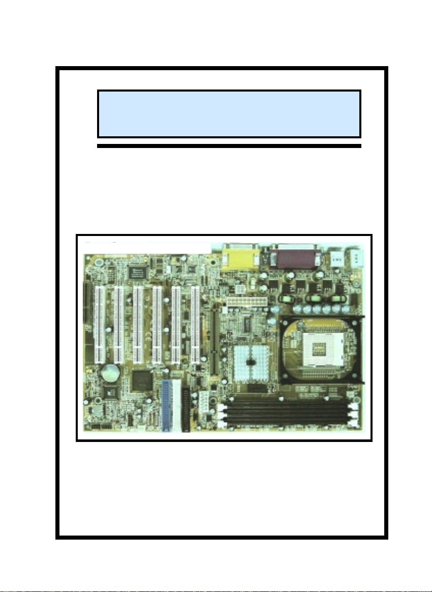
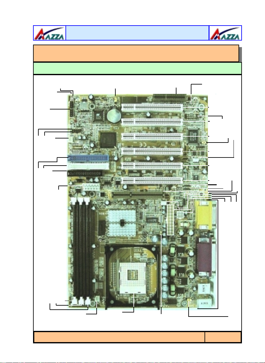
1.1. Mainboard Layout ..................................................................................... 5
1.2. Overview ................................................................................................... 6
1.2.1. Mainboard Series ...................................................................................6
1.2.2. Mainboard Dimensions ...........................................................................6
1.2.3. Environmental Limitations.......................................................................6
1.3. Features and Specifications ...................................................................... 6
1.4. System Health Monitor Functions ............................................................. 9
1.4.1. Hardware Monitoring System Utility.........................................................9
1.4.2. Installation ............................................................................................10
1.5. System Intelligence .................................................................................. 10
Chapter 2:- Hardware Installation
Page 11
2.1. Installation Checklist ................................................................................ 11
2.2. Installation Steps...................................................................................... 12
2.3. Expansion Cards, Connectors and Jumpers............................................... 13
2.4. CPU, Memory and Expansion Slots............................................................ 14
2.4.1. Installation of the CPU............................................................................14
2.4.2. Memory Modules....................................................................................14
2.4.3. PCI Slots ...............................................................................................15
2.4.4. AGP (Accelerated Graphics Port) Slot.......................................................16
2.4.5. CNR (Communications Network Riser) Slot ..............................................16
2.5. Internal Connectors .................................................................................. 16
2.5.1. Floppy Disk Drive (FDD) .........................................................................16
2.5.2. Primary and Secondary IDE Connectors...................................................17
2.5.3. CPU and Chassis Fan Connectors ............................................................17
2.5.4. ATX Power Supply Connectors ................................................................17
2.5.5. WOL (Wake-On-LAN) Connector .............................................................18
2.5.6. CD Audio In/AUX-In/Video-In Connectors................................................19
2.5.7. USB Connectors.....................................................................................19
2.5.8. Smart Card Reader (SCR) Connector.......................................................20
2.5.9. Memory Stick/SD Connector ...................................................................20
2.6. System Panel Buttons and LED Connectors .............................................. 20
2.6.1. PW: Power On/Off and External Suspend Switch Connector.......................21
2.6.2 Standby LED Connector...........................................................................21
2.6.3. IDE HDD LED Connector ........................................................................21
2.6.4. Reset Button Connector...........................................................................21
Table of Contents

The
AZZA
845S MAINBOARD SERIES
Page 4
2.7. Speaker and Power LED Connector........................................................... 22
2.7.1. Speaker Connector...................................................................................22
2.7.2. Front Panel Power LED Connector.............................................................22
2.8. External Connectors.................................................................................. 22
2.8.1. PS/2 Keyboard Connector.........................................................................22
2.8.2. PS/2 Mouse Connector .............................................................................22
2.8.3. COM 1 and COM 2 Connectors..................................................................23
2.8.4. Parallel Port Connector.............................................................................23
2.8.5. USB 1 and USB 2 Ports.............................................................................23
2.8.6. Audio Game Port Connector......................................................................23
2.9. Jumper Settings ........................................................................................ 23
2.9.1. JP 1: Keyboard/Mouse Power On ..............................................................24
2.9.2. JP 2: CPU FSB Clock Speed Selection.........................................................24
2.9.3. JP 3: STR Function...................................................................................24
2.9.4. JP5: Voice Alarm Language Selection ........................................................25
2.9.5. JP6: Clear Password.................................................................................25
2.9.6. JP7: USB3/4 Wake Up From STR Mode......................................................25
2.9.7. JP8: Memory Stick Reader Selection..........................................................25
2.9.8. JP11: Clear CMOS ....................................................................................25
Chapter 3:- Managing The PC BIOS
Page 26
3.1. AWARD BIOS CMOS Setup Utility........................................................... 26
3.2. Main Menu.............................................................................................. 26
3.3. Standard CMOS Setup ............................................................................ 27
3.4. Advanced BIOS Features........................................................................ 29
3.5. Advanced Chipset Features .................................................................... 32
3.6. Integrated Peripherals ........................................................................... 34
3.7. Power Management Setup ..................................................................... 39
3.8. PNP/PCI Configuration .......................................................................... 41
3.9. PC Health Status .................................................................................... 42
3.10. Frequency/Voltage Control .................................................................... 43
3.11. Load Optimized Defaults ........................................................................ 44
3.12. Set Supervisor Password........................................................................ 45
3.13. Set User Password.................................................................................. 45
3.14. SAVE & EXIT SETUP/EXIT WITHOUT SAVING........................................ 47
Table of Contents

The
AZZA
845S MAINBOARD SERIES Page 5
Chapter 1
Chapter 1
Chapter 1 -
-
-Introduction
Introduction
Introduction
1.1. MAINBOARD LAYOUT
CN17: FAN2
CN15-A: ATX Power
CN15-B: 2x2 ATX Power PC 99 ATX
Connector
CN8: FDC
CN10: IDE2
CN9: IDE1
SPKR
PWR-LED
Front Panel and Power
LED Connectors CN30: USB3
CN31: USB4
CN27: FAN3 CN15-C: Aux-Power Connector DIMM3
DIMM2
DIMM1
CN13:
FAN1
CPU
Socket
JP1: KB/MS
Power On
JP2:
CPU
FSB
Clock
CN21: CD-IN
AGP Slot
CN44: Video-IN
CN45: AUX-In
CN16: WOL
JP6: Clear Password
CN41: SCR
PCI 6 PCI5 PCI4 PCI3 PCI2 PCI1
CN43:
MS/SD
CNR
JP11:
Clear
CMOS
Introduction

The
AZZA
845S MAINBOARD SERIES
Page 6
Processor
Supports Intel® Socket 478 Pentium 4.
Chipset
Northbridge: RG82845
Southbridge: FW82801BA
I/O Chipset
845S-AD: Winbond W83637HF-AW
845S-AV: Winbond W83627HF-AW
1.2.1. Mainboard Series
The 845S mainboard series use a Pentium 4 CPU with an Intel 845 chipset.
There are two models to choose from. A deluxe model, the 845S-AD, and a value
model, the 845S-AV.
1.2.2. Mainboard Dimensions
Width & Length: 305 mm x 200 mm
Thickness 1.57 mm
1.2.3. Environmental Limitations
Operating Temperature: 10°C to 40°C . (50°Fto 104°F)
Required Airflow: 50 linear feet per minute across CPU.
Storage Temperature: - 40°C to 70°C. (- 40°F to 158°F)
Humidity: 0 to 90% non-condensing.
Altitude: 0 to 10,000 feet
1.3. Features and Specifications
CN 1: PS/2 KB
CN 2: PS/2 MS
CN 6: USB 1 CN 3:COM 1 CN 4: COM 2
CN 5: LPT CN18: Game/MIDI Port
SPK-OUT LINE-IN MIC-IN
CN 7: USB 2
PC 99 ATX External Connector
1.2. Overview
Introduction

The
AZZA
845S MAINBOARD SERIES Page 7
CPU Switching Voltage Regulator
Equipped with a switching voltage regulator that automatically detects +1.10V to
+1.85V DC power supply.
System Memory
These mainboards each have three 168-pin DIMM modules onboard. These mod-
ules are able to support 3.3V PC-133 SDR SDRAM modules. A maximum memory
of 3GB is supported.
Expansion Slots
These mainboards are equipped with six dedicated PCI slots, one CNR slot and
one 4x AGP slot. PCI 6 and the CNR slot are shared slots.
Onboard Audio Features
Supports Microsoft DirectSound/ DirectSound 3D and AC97 Full Duplex.
Word Size
• Data Path: 8-bit, 16-bit, 32-bit, 64-bit
• Address Path: 32-bit
Front Side Bus Frequency (FSB)
For a P4 Socket 478 CPU a 400 MHz FSB (100 MHz QDR) is supported.
BIOS
•2Mb Flash ROM
• Award BIOS, Windows 95/98 Plug and Play (PnP) compatible.
• Supports SCSI sequential boot-up.
• Flash EPROM for easy BIOS upgrades.
• Supports DMI 2.0 function
Desktop Management Interface (DMI)
The mainboard comes with DMI 2.0 built into the BIOS. The DMI utility in the
BIOS will automatically record different information about your system configura-
tion and store this information in the DMI pool, which is a part of the system
board's Plug and Play BIOS. DMI, along with the appropriately networked soft-
ware, is designed for easy inventory, maintenance and the simplified trouble-
shooting of computer systems.
WOL (Wake-On-LAN) Port
One WOL connector supports Wake-On-LAN functionality.
Introduction

The
AZZA
845S MAINBOARD SERIES
Page 8
USB Ports
The mainboard is equipped with Four Version 1.1 USB ports. USB allows data
exchange between your computer and a wide range of simultaneously accessible
external Plug and Play peripherals. USB 1 and USB 2 are external ports. They can
be found on the PC 99 ATX connector. USB 3 and USB 4 are non-standard
internal connectors that can be used to connect other USB devices.
Connectors
•Two IDE connectors.
•One floppy drive interface supports up to two 2.88MB floppy drives.
•One 20-pin ATX power supply connector.
•One 2x2 ATX 12V power supply connector.
•One 1x6 ATX Auxiliary power supply connector.
• CPU and chassis fan connectors.
• One CD audio-in connector.
• One Aux-IN Connector
• One Video-IN Connector
• Οne Smart Card Reader (SCR) for use with a Smart Card Reader Kit.
(Only for 845S-AD)
ATX Double Deck Ports (PC 99 color-coded connectors)
)
•Two USB ports.
•Two external DB-9 serial port connectors: COM 1 and COM 2 (UART).
•One SPP/ECP/EPP DB-25 parallel port.
•One mini-DIN-6 PS/2 mouse port.
•One mini-DIN-6 PS/2 keyboard port.
•One game/MIDI port.
•Three audio jacks: speak-out, line-in and mic-in.
PCI Bus Master IDE Controller
•Two PCI IDE interfaces support up to four IDE devices.
•Both models support ATA/33, ATA/66 and ATA100 hard drives.
•PIO Mode 3 and Mode 4 Enhanced IDE (data transfer rate up to 16.6MB/
sec.).
•Bus mastering reduces CPU utilization during disk transfer.
•Supports ATAPI CD-ROM, LS-120 and ZIP.
Optional cables for USB 3 and USB 4 must be purchased separately.
These cables should have a connector on either end. One of these con-
nectors should be a standard USB connector. The other connector
should be compatible with the USB 3/4 connectors on your mainboard.
Introduction

The
AZZA
845S MAINBOARD SERIES Page 9
The mainboard is capable of monitoring the following health conditions of your
system:
1. Processor temperature. It has an overheat alarm.
2. VCORE/3.3V/5V/12V/-12V voltages and failure alarm.
3. Processor and chassis fan speeds. It has a failure alarm for these fans.
4. Read back capability that displays temperature, voltage and fan speed.
1.4.1. Hardware Monitoring System Utility
The mainboard comes with the Hardware Monitoring System utility contained on
the CD. It is capable of monitoring the system’s hardware conditions such as the
temperature of the processor, voltage, and the speed of both the CPU and chassis
fans. You are allowed to manually set a range to the items being monitored. If the
values are over or under the set range a warning message will automatically pop
up. We recommend that you use the Default Settings, which are the ideal settings
that will maintain the system in a good working condition.
Only use this utility in Windows ® 95 or Windows ® 98 operating systems.
Special Features for the 845S-AD Model
ALARM
The ALARM is an intelligent voice debugging device. When you boot your system
it examines the status of your system to determine if the system is operating cor-
rectly. If a device is incorrectly installed, not installed or damaged a voice an-
nouncement will be made. Devices which are supported by this alarm are: CPU,
Memory, Video Card, FDD, HDD, Keyboard and Battery.
Special Features
Utility Panel: Front USB
The Front Utility Panel is a unique design concept that brings USB ports to the
front of your system. USB 3 and USB 4 can be connected to these ports. The
Front Utility Panel is shown below.
Front Utility Port
1.4. System Health Monitor Functions
Introduction

The
AZZA
845S MAINBOARD SERIES
Page 10
1.4.2. Installation
Click the Hardware Monitoring button, choose the chipset, model number and the
OS that is installed. Please refer to the CD “Readme” file for further installation
instructions.
Dual Function Power Button
Depending on the setting in the Soft-Off By Power-Button field of the Power
Management Setup, this switch allows the system to enter the Soft-Off or
Suspend mode.
RTC Timer to Power-on the System
The RTC installed on the system board allows your system to automatically
power-on at a set date and time.
Wake-On-LAN Ready
The Wake-On-LAN function allows the network to remotely wake up a Soft Power
Down (Soft-Off) PC. Your LAN card must support the remote wakeup function.
The 5V SB power source of your power supply must be at least 720mA.
ACPI Ready
The mainboard is designed to meet the ACPI (Advanced Configuration and Power
Interface) specification. ACPI has energy saving features that support OS Direct
Power Management (OSPM) for round the clock PC operation.
1.5. System Intelligence
Introduction

The
AZZA
845S MAINBOARD SERIES Page 11
Chapter 2
Chapter 2
Chapter 2 -
-
-Hardware Installation
Hardware Installation
The following is a checklist of all the expansion slots, jumpers and connectors that should be
configured on your mainboard before you can run your pc.
2.1. Installation Checklist
Installation Checklist
Expansion Slots and Sockets
CPU Slot
DIMM Slots
PCI Slots
CNR Slot
AGP Slot
Socket 478 CPU Slot which supports Pentium 4
Three 168 pin slots that support up to 3GB of SDRAM.
Six 32 bit PCI Slots.
One Communications Network Riser Slot
One Accelerated Graphics Port Slot
Internal Connectors
CN8
CN9
CN10
CN13
CN15-A
CN15-B
CN15-C
CN16
CN17
CN21
CN27
CN30
CN31
CN41
CN43
CN44
CN45
Floppy Disk Drive
Primary IDE
Secondary IDE
CPU Fan
ATX Power Supply
ATX 12V Power Supply
Auxiliary ATX 12V Power Supply
Wake On Lan
Chassis Fan 1
CD Audio In
Chassis Fan 2
Universal Serial Bus 3
Universal Serial Bus 4
Smart Card Reader
Memory Stick SD
Video In
Auxiliary In
FDC
IDE1
IDE2
CPU Fan
ATX
ATX12V
Aux.
WOL
FAN2
CD-In
FAN3
USB3
USB4
SCR (only for 845S-AD)
MS/SD (only for 845S-AD)
Video-IN
Aux-IN
CN1
CN2
CN3
CN4
CN5
CN6
CN7
CN18
PS/2 Keyboard Connector
PS/2 Mouse Connector
Serial Port 1
Serial Port 2
Parallel Port
Universal Serial Port 1
Universal Serial Port 2
Game/Audio Port
PS/2 KB
PS/2 MS
COM1
COM2
LPT
USB1
USB2
Audio/Game
External Connectors
Hardware Installation

The
AZZA
845S MAINBOARD SERIES
Page 12
You need to complete the following installation steps before you can use your PC.
•Check and Set the Mainboard Settings.
•Install the Central Processing Unit (CPU).
•Install the Memory Modules.
•Install the Expansion Cards.
•Connect the Ribbon Cables, Panel Wires and the Power Supply.
•Setup the system BIOS
Before you start installing your mainboard we strongly recommend that you use a
grounded anti-static mat. We further recommend that you attach an anti-static wrist-
band, which is grounded at the same location as the mat, to your wrist.
2.2. Installation Steps
Only use an ATX12V Power Supply.
Installation Checklist (Continued)
System Panel Buttons and LED Connectors
PW
S3L
HL
RS
Power On/Off and Suspend Switch Connector.
STR LED Connector (only for 845S-AD)
HDD LED Connector
Reset Button Connector
Speaker and Power LED Connector
PWR-LED
SPK Power LED
Speaker Connector
Jumpers
JP1
JP2
JP3
JP5
JP6
JP7
JP8
JP11
KB/MS PWR-ON
CPU FSB Clock Selection
S3 (STR) Function (only for 845S-AD)
Voice Warning Language Selection (English/Chinese) (only for 845S-AD)
Clear Password
USB 3/4 Wake Up From STR (only for 845S-AD)
Memory Stick Reader Selection (only for 845S-AD)
Clear CMOS
Hardware Installation

The
AZZA
845S MAINBOARD SERIES Page 13
2.3. Expansion Cards, Connectors and Jumpers
PCI1
JP3: S3 (STR) Function
CN15-C: Auxiliary Power Supply
DIMM3
DIMM2
DIMM1
CN13: FAN 1
1
PCI2PCI3PCI4PCI5PCI6
JP5:
English/
Chinese
11111
1
1 PWR-LED
1 SPKR
PW S3L HL RS
11 11
CN9: IDE 1 CN10: IDE 2
1
JP11: Clear
CMOS
CN30: USB3
CN31: USB4 CN27: FAN3
JP7: USB3/4 STR
1
1
CNR
Slot
CN43:MS/SD
11 CN41:
SCR
JP8: MS Reader Select
JP6: Clear
Password
1
CN16:
WOL
CN36:
S/PDIF
1
CN44: VIDEO-IN
CN45: AUX-IN
111
AGP
Slot
CN21: CD-IN
CN15-B: ATX12V JP1:KB/MS
PWR ON
1
1
1
CN17:
FAN2 JP2: CPU
FSB Clock
CN15-A: ATX
Power Supply
CN8: FDC
PCI1
JP3: S3 (STR) Function
CN15-C: Auxiliary Power Supply
DIMM3
DIMM2
DIMM1
CN13: FAN 1
1
PCI2PCI3PCI4PCI5PCI6
JP5:
English/
Chinese
11111
1
1 PWR-LED
1 SPKR
PW S3L HL RS
11 11
PW S3L HL RSPW S3L HLPW S3L HL RS
11 11
CN9: IDE 1 CN10: IDE 2
1
JP11: Clear
CMOS
CN30: USB3
CN31: USB4 CN27: FAN3
JP7: USB3/4 STR
1
1
CNR
Slot
CN43:MS/SD
11 CN41:
SCR
JP8: MS Reader Select
JP6: Clear
Password
1
CN16:
WOL
CN36:
S/PDIF
1
CN44: VIDEO-IN
CN45: AUX-IN
111
AGP
Slot
CN21: CD-IN
CN15-B: ATX12V JP1:KB/MS
PWR ON
1
1
1
CN17:
FAN2 JP2: CPU
FSB Clock
CN15-A: ATX
Power Supply
CN8: FDC
Hardware Installation

The
AZZA
845S MAINBOARD SERIES
Page 14
2.4.1. Installation of the CPU
To install your processor, please complete the following set of instructions
1. Locate a small dot marked on the top of the CPU. This mark indicates Pin
1 of the CPU.
2. Locate Pin 1 for the Socket on the mainboard.
3. There is a lever on the side of the socket. First push this lever sideways
and then lift it to a 90-degree angle.
4. Insert the CPU into the Socket. Please make sure that Pin 1 for the CPU
is inserted into Pin 1 of the Socket.
5. When the CPU is installed correctly push the lever back into place.
6. Install a proper heat sink with cooling fan for proper heat dissipa-
tion. Failing to install a heat sink with cooling fan may cause overheating
which will burnout your CPU and damage your mainboard. The heat sink
with cooling fan should be installed on the retention mechanism that is
provided. This retention mechanism is designed to hold the bigger Heat
Sink that is required for the Pentium 4 CPU.
2.4.2. Memory Modules
These mainboards all have three 168-pin SDR SDRAM slots. The SDR SDRAM slots
are located on the right hand side of the board. To install the DIMM’s into these
slots, make sure the white lever at each side of the slot has been pulled down to
an angle of approximately 45°. Make sure that the DIMM is in the correct orienta-
tion. Place the DIMM on the slot and push down firmly.The white levers will come
back up and lock the module in place.
These mainboards support 133MHz SDR SDRAM. SDR SDRAM memory devices
with densities of 64Mb, 128Mb, 256Mb and 512Mb technology x8 or x16 are sup-
ported by the Intel 845 chipset memory interface. Three double sided DIMMs
with unbuffered PC133 can be supported. A maximum memory bandwidth of 1GB/
s is possible with PC133.
Heat Sink and Retention Mechanism
You must use an Intel approved Heat Sink. This CPU operates at a very high fre-
quency and therefore heats up very quickly. (A normal heat sink will not be ade-
quate to cool the CPU and the CPU will burn-out.) These heat sinks are very
heavy. A retention mechanism for the Heat Sink has been provided with the main-
board.
2.4. CPU, Memory and Expansion Slots
Hardware Installation

The
AZZA
845S MAINBOARD SERIES Page 15
Top View of a 168-pin DIMM Slot
10 Pins 30 Pins 44 Pins
Important: The DIMM’s can only be fitted into the slots in one orientation. Make
sure that the DIMM’s are in the correct orientation and the pins are correctly
aligned before you insert them.
2.4.3. PCI Slots
These boards come with six PCI slots. They are located on the left hand side of
the board. Both PCI and PCI expansion cards may require IRQ’s. This mainboard
complies with Plug and Play (PnP) specifications. Whenever a PnP compliant card
is added the system will automatically be configured and the IRQ’s will be as-
signed automatically.
When you are inserting your PCI card make sure that the pins are correctly
aligned. When the pins are properly aligned with the hole’s in the slot, push down
gently.
11 pins 49 pins
Top View of a PCI Slot
NOTE: “Out Of Memory” Error Message
If you have installed more than 512 MB of RAM and are running Microsoft Windows Millennium Edition, Win-
dows 98 Second Edition, Windows 98 or Windows 95 you may experience memory problems. Two symptoms
of these problems are being unable to runan MS-DOS session while you are running Windows or the computer
may stop responding while Windows isstarting.
Thereare three possible solutionsto thisproblem:
1) Reduce the amount of memory Vcache uses to 512 MB or less by altering the MaxFileCache setting in
the System.ini file.
2) Use the System Configuration Utility to reduce the amount ofmemoryWindows uses to 512 MBor less.
3) Reduce the memory installed on your computer to 512 MB or less.
This problem can also occur if you are using an Advanced GraphicPort (AGP) video adapter.
Hardware Installation

The
AZZA
845S MAINBOARD SERIES
Page 16
2.4.4. AGP (Accelerated Graphics Port) Slot
AGP is a dedicated bus slot. It operates at 66 MHz and transfers data at a rate up
to 1066 MB/s. This allows 3D applications to run more smoothly. The 845S main-
boards each come with one AGP slot. This slot is able to support 1x, 2x and 4x
AGP cards.
Only 1.5 volt AGP graphic cards are supported by the Intel® 845 chipset
motherboards. If a 3.3 volt AGP card is used in an Intel® 845 chipset
based motherboard there is a high probability of damaging the chipset,
the mainboard and the CPU.
Top View of a 1X/2X/4X (1.5V only) AGP Slot
21 pins 41 pins
2.4.5. CNR (Communications Network Riser) Slot
This slot integrates audio, modem and networking on the same card. CNR specifi-
cations support the Audio Codec 97 (AC 97) interface, LAN interfaces, USB inter-
faces and System Management Bus (SMBus) interfaces (used specifically to pro-
vide Plug and Play functionality).
11 pins 19 pins
Top View of an CNR Slot
2.5.1. Floppy Disk Drive (FDC)
Connector: CN 8
Type: 34 pin block
The FDD connector can support two Floppy drives. It is located at the front of the
mainboard. To connect, use the ribbon-cable that has been provided. Make sure
that the red strip is connected to PIN 1 of the connector.
PIN 1
17 Pins
Top View of a Floppy Disk Drive
Connector
2.5. Internal Connectors
Hardware Installation

The
AZZA
845S MAINBOARD SERIES Page 17
2.5.4. ATX Power Supply Connectors (CN15-C optional)
Connector: CN 15-A/ CN15-B/ CN15-C
Type: 20 pin block/2x2 12V/1x6 Auxiliary
The mainboards in this series all come with three onboard power supply connec-
tors labled from CN15-A to CN15-C. CN15-A and the CN15-B are regular ATX
power supply connectors that have been used on all recent motherboards. The
CN15-C power connector is for a +3.3V and +5V power supply. These increased
power supplies are necessary to provide extra power for the slot. The ATX 12V
power supplies are all downward compatible with standard ATX power supplies.
2.5.2. Primary and Secondary IDE connectors
Connector: CN 9 (primary)/ CN 10 (secondary)
Type: 40 pin blocks
The 845S mainboards all have two IDE connectors: a primary and secondary.
Each IDE connector can support two IDE drives. These mainboards can therefore
support up to four IDE devices each. If you install two hard drives, you need to
configure the second drive to slave mode in the BIOS setup
.
Please refer to your
hard drive manual for the appropriate jumper settings.
Top View of an
IDE Connector
20 PINS
PIN 1
2.5.3. CPU Fan and Chassis Fan Connectors
Connector: CN 13 (CPU Fan 1)/CN 17 (Chassis Fan 1)/CN 27 (Chassis Fan 2)
Type: 3 pin
The cooling fans must be connected to their respective power connectors.
Fan Signal +12V DC
Ground
1 Ground
2 +12V DC
3 Fan Signal
Top View of a Fan Connector Front View of a Fan Connector
Hardware Installation

The
AZZA
845S MAINBOARD SERIES
Page 18
2.5.5. WOL (Wake On LAN) Connector
Connector: CN 16 (WOL)
Type: 3 pin
The WOL connector must be connected to a LAN card that has Wake-On-LAN
(WOL) output. This connector powers up the system when a wakeup packet or
signal is received through the LAN card.
In order to use the WOL LAN card to trigger the power on the PC system, the
switching power supply must have the ability to provide a driving current of at
least 720 mA and be connected to a “5V standby” voltage.
WOL/WOM
5V_SB
Ground
1 5V_SB
2 Ground
3 WOL/WOM
Top View of a WOL Connector Front View of a WOL Connector
ATX Power Supply Connector
Pin 1 Pin 11
+3.3VDC
+3.3VDC
COM
+5VDC
COM
+5VDC
COM
PWR_OK
+5VSB
+12VDC
+3.3VDC
-12VDC
COM
PS_ON#
COM
COM
COM
-5VDC
+5VDC
+5VDC
Pin 1 Pin 3
COM
COM
+12VDC
+12VDC
ATX12V Power Supply Connector
COM
COM
COM
+3.3VDC
+3.3VDC
+5VDC Pin 6
Pin 5
Pin 4
Pin 3
Pin 2
Pin 1
Auxiliary Power Supply Connector
Hardware Installation

The
AZZA
845S MAINBOARD SERIES Page 19
2.5.6. CD-IN/VIDEO-IN/AUX-IN Connector
Connector: CN 21 (CD-IN)/ CN 44 (VIDEO-IN) / CN 45 (AUX-IN)
Type: 4 pin un-housed
This mainboard has one CD-IN connector, AUX-IN connector and VIDEO-IN con-
nector. The CD-IN connector is used to connect the CD ROM audio out.allows you
to receive audio input from the CD ROM. The AUX-IN connector allows you to
receive signals from other audio devices like a radio or tape. The VIDEO-IN con-
nector allows you to receive signals from devices like TV tuners, Video machines
and Video cameras.
2.5.7. USB Connectors: USB3 and USB4
Connector: CN 30 (USB3)/ CN 31 (USB4)
Type: 5 pin
This mainboard comes with 2 extra onboard USB ports. Ribbon cable for these
four connectors are optional. These connectors allow you to connect 2 extra USB
devices to the mainboard. It should be noted that these USB connectors are non-
standard and the cable you purchase should therefore have, on one side, a con-
nector which is compatible with the on-board USB connector and on the other side
a standard USB connector.
Right Channel
CD-IN/
AUX-IN/
VIDEO-IN
Left Channel
CD-IN/
AUX-IN/
VIDEO-IN
Ground
1 Left Channel CD/ AUX/ VIDEO-IN
2 Ground
3 Ground
4 Right Channel CD/ AUX/ VIDEO-IN
Top View of a CD/AUX/
VIDEO-IN Connector Front View of a CD/AUX/VIDEO-IN
Connector
Ground
5V DC
Ground
Ground Data -
Data +
1 5V DC
2 Data-
3 Data+
4 Ground
5 Ground
Top View of a USB Port Front View of a USB Port
Hardware Installation
This manual suits for next models
2
Table of contents
Other AZZA Motherboard manuals