Silverwing AEROPRAKT A22 FOXBAT User manual

Pa
g
e 2 - © SilverWin
g
Aviation
,
2005

Pa
g
e 3 - © SilverWin
g
Aviation
,
2005
Introduction to the Aeroprakt A22 Foxbat
The prototype A22 was conceived during 1996 on the drawing board of
Antonov Design Bureau engineer Yuri Yakovlev - purely as an easy-to-fly
450-525 kg aircraft with excellent pilot and passenger comfort and
competitive all-round performance. It was intended that pilots of average
ability would be able to operate the A22 in safety from the typically short
ultralight airstrips found around the world.
The design is aimed squarely at the growing ultralight market in Western
Europe and the USA although examples are also operating in UAE, Malaysia
and Eastern Europe. In Germany the A22 has achieved certification to the
stringent BFU-95 requirements. Approval in UK to BCAR'S' via PFA
engineering was achieved in late 2001. Standard engine is the 100 bhp
Rotax 912ULS, with the 80 bhp 912UL available as an option.
Known in Australia South Africa and the UK as the ‘Foxbat’, the A22 is a
quality-engineered aircraft with no aerodynamic vices. The airframe is in
riveted aluminium with part Ceconite type fabric-covered wings and control
surfaces. It retains adequate control response in all axes at speeds down to
30 kts and provides the unthreatening STOL capability of a genuine
ultralight. Yet it can cruise at 85-90kts on 14ltrs/hr and has a range of more
than 500 miles. The cockpit is very roomy with excellent visibility and
plenty of luggage space in a container behind the seats.
This aircraft is an excellent choice for pilots of either ultralights or GA light
aircraft. Equally at home on short ultralight airstrips or GA bitumen the
Foxbat is a plane that can introduce light aircraft pilots to a much wider
choice of destinations, and give ultralight pilots a level of speed and, in
particular comfort, previously unavailable within the weight limit.
Building the Foxbat
Although the Foxbat is a modern aircraft in concept it uses a very
conventional method of construction in riveted Alclad aluminium. The kit is
supplied with some of the fuselage, much of the wings, tailplane, fin and
control surfaces pre-riveted. The builder’s riveting (using ‘pop’ rivets)
consists of fitting the cabin floor-pan (which is partly pre-drilled), finishing
and riveting the wing and fin tips, securing the fin itself and various
mounting brackets and webs to the bare fuselage monocoque. Final riveting
includes all the glazing, including the windscreen.
The A22 Build Manual is illustrated with around 100 exploded-view drawings
that cover each step of the assembly process together with easy-to follow

Pa
g
e 4 - © SilverWin
g
Aviation
,
2005
text. As an option, a full set of engineering reference drawings is available
on CD at extra cost.
The bulk of the airframe construction work is centred on the fuselage and
consists of fitting the control mechanisms (torque tubes, push rods,
bell-cranks, cables, etc) the main components of which are factory
finished, anodised and/or plated. The factory requires the wings, tailplane
and control surfaces to be pre-riveted in jigs leaving the builder to add the
fuel tanks, as well as covering and painting. At every point where a rotating
action takes place, an aerospace-quality rose-joint or bearing is pre-pressed
into the bracket.
The airframe can be assembled and finished to a rolling but bare stage
before buying the engine, instruments and covering system. This means
purchases of major items can be staggered to suit the budget or build
schedule – for example, if six months or more is planned to build the plane,
there is little point in having an expensive engine bolted to the airframe (or
in a box) using up its warranty time. After installing the engine the final
finishing involves installing and connecting the fuel tanks, covering and
painting, and fitting instruments, windscreen, and other glazing.
One person, working at a steady and meticulous pace can build a finished
aircraft from a Foxbat kit in around 500 hours (or fewer with an assistant) -
some jobs need extra hands for completion. With good planning, a largish
double garage will be a big enough workshop space to complete all the
sub-assemblies (including covering and painting them) providing the wings
and tailplane are stored elsewhere while work progresses on the fuselage.
Obviously a larger space is required for the final assembly of the aircraft
although this can be done outdoors prior to Final Inspection and trailer
transportation to the airfield for Test Flying. With a little practice, two
people can detach the standard wings quite easily in about 30 minutes. Re-
assembly takes about the same.

Pa
g
e 5 - © SilverWin
g
Aviation
,
2005
INTRODUCTION TO BUILDING
Before you begin….
1. Thoroughly read through the complete construction manual several
times so you are completely familiar with each stage of the process.
2. Make sure you understand all the diagrams/drawings.
3. Check your parts against the parts list to ensure you have all the items
you need.
4. Prepare your workshop and collect together all the tools you need.
Construction of the Foxbat requires no really specialised tools – a set of
metric spanners, a hand pop-rivet gun, flat and cross-head
screwdrivers, long-nose and standard pliers some files and cutters are
the main requirements. Later, you will need lifting tackle for the
engine – but this can be hired for the day or so you will need it.
5. If you are buying the kit in stages, plan when you will need the engine,
covering/paint and instruments, so that they can be ordered in plenty
of time.
6. If you are in doubt about anything – call SilverWing Aviation for
clarification. Once a hole is drilled, it can’t be un-drilled! So take your
time.
7.
8. Constructing your Foxbat should be an enjoyable experience – much of
it is an assembly process, with actual making of parts kept to the
minimum - many of the rivet holes are measured and, in some cases,
drilled. Final covering and painting the aircraft is a straightforward if
time consuming job which done well will give you an aircraft which will
not only fly well but will last you many years.
9. Should you require assistance at any time, just contact SilverWing
Aviation for help and guidance.
10. Happy constructing!
SilverWing Aviation, PO Box 9050, Gold Coast MC, Qld 9726
(07) 5597 0391 & 0413 900 892

Pa
g
e 6 - © SilverWin
g
Aviation
,
2005
AEROPRAKT A22 FOXBAT
PARTS LIST
REGIME - ITEM NUMBER - PART DESCRIPTION - (DRAWING NUMBER) - AEROPRAKT
NUMBER
FUSELAGE/WINGS/ETC
1. MONOCOQUE (1.050+) 2.0100
2. WING R/L (6.500) 3.2000
3. STRUT R/L (4.510) 3,2900
4. FLAPERON R/L (6.500) 0.3700
5. FIN (2.030+) 1.3400
6. RUDDER ((3.500) 0.3300
7. TAILPLANE (8.500) 1.3100.00
8. ELEVATOR (8.500) 3.3200
9. TRIM TAB (9.500) 1.4000
10. BEAM R/L (1.010) 0.0116
11. LG BEAM R/L (1.020) 0.4350
12. GUSSET R/L (1.030) 0.0148
13. ANGLE R/L (1.030) 0.0149
14. ANGLE R/L (1.030) 0.0150
15. HINGE X 4 (1.040) 0.1391
16. SUPPORT (1.130) 0.0156
17. BASEPLATE (1.140) 0.0164
18. BRACKET R/L (1.140) 0.0108
19. LG BRACKET R/L (1.150) 1.4130
20. LG BRACE R/L (1.150) 0.4150
21. LG BRACKET R/L (1.160) 0.4140
22. FITTING (1.160) 0.4150
23. BRACE R/L (1.050) 1.1371
24. BRACE R/L (1.050) 1.1372
25. BRACE R/L (1.060+) 1.1373
26. FITTING X 9 (1.070 +) 1.1377
27. BRACKET (18.010) 0.7625
28. BRACE X 3 (1.090/110) 1.1374
29. BRACE X 3 (1.090 +) 1.1375
30. BRACE X 3 (1.100 +) 1.1376
31. FLOORING (1.170) 0.0119
32. ANGLES R/L (1.180) 0.0171
33. DOUBLER (1.190) 0.0172
34.
DOUBLER X 2 (1.190) 0.0173
35. SUPPORT (1.200) 3.4307
36. GUSSET X 2 (1.200) 3.4307
37. FLOORING (1.210) 0.0120
38. GUSSET R/L (1.220) 2.0147
39. BEAM (1.310) 1.0121
40. ANGLE (1.310) 0.0194
41. BELT (18.020) 0.7626
UNDERCARRIAGE
1.MAIN LEG R/L (1.270) 5.4110
2.AXLE X 2 (1.300) 3.4133.BLOCK X
2 (1.300) 8.4121
4.PLATE X 2 (1.300) 3.4123
5.MATCO 5.00-5 (+ BRAKE) X 2
6.SUPPORT (1.280) 3.4308
7.FLANGE (1.280) 3.4324
8.STRUT (1.280) 3.4300
9.NOSELEG (1.290) 3.4300
10.MATCO 6.00-6
11.AXLE (1.290) 1.4301
12.SPACER X 2 (1.290) 1.4316
MOULDINGS, ETC
1.PROP: SPINNER
2.SPINNER BACKPLATE
3.ENGINE COWLING UPPER
4.ENGINE COWLING LOWER
5.WING FILLETS R/L 0.1500
6.WHEELSPAT FRONT
7.WHEELSPAT RIGHT
8.WHEELSPAT LEFT
9.FIN CAP 0.3409
10.FLAPERON COWL 1.5400.04
11.CENTRAL CONSOLE 0.7152
12.INST: HOUSING 1.7151
13.INST: PANEL DURAL: 0.7001
14.INST: PANEL CARBON
15.WINDSCREEN 0.1301.00
16.SIDEWINDOW R/L 0.1301.01
17.TOPWINDOW 0.1303
18.PITOT HEAD/TUBES
FUEL SYSTEM
1. TANK R/L (17.100) 3.6120.00
2. FAIRING (18.100) 0.7627.01
3. GASCULATOR (SKYCRAFT,ETC)
4. J/TUBE (17.010) 3.6100.01
5. F/COCK X 2 (17.100)
6. T/PIECE X 2 (17.020)
7. DRAIN VALVE (17.020)

Pa
g
e 7 - © SilverWin
g
Aviation
,
2005
ENGINE AND ANCILLARIES
1. E/MOUNT (10.010+) 0.6401.01
2. E/MOUNT (10.010+) 0.6402.00
3. BRACKET (10.020+) 0.6402
4. ROD (10.020) 0.6403
5. LUG (10.020) 0.6401
6. BEARINGS (10.020) 0.6404
CONTROLS (THROTTLE/CHOKE)
1. BRACKET L (16.010) 3.6018
2. BRACKET R (16.010) 3.6019
3. T/LEVER L (16.010+) 3.6025
4. T/LEVER R (16.010+) 3.6026
5. C/TUBE (16.010) 3.6021
6. F/CLAMP (16.010) 3.6029
7. SPACER (16.010) 3.6016
8. C/STOP (16.020) 3.6017
9. SHACKLE (16.020) 3.6023
10. HANDLE (16.020) 1.6028
11. I/CABLE (16.020+) 2.6040
12. O/CABLE (16.020+) 2.6041
13. C/LEVER (16.030) 1.6051
14. C/CABLE (16.030+) 1.6055
15. BRACKET (16.040) K20.2.42.02
16. J/BLOCK (16.040) K20.0.42.03
17. COVER (16.040) K20.2.42.05
18. CABLE X 2 (16.040) 1.6056
19. B/CABLE X 2 (16.050) 3.6040.00
CONTROLS (PEDALS)
1. PEDALS (11.050) 4.5210.01C6
2. PEDALS (11.050) 4.5210.02C6
3. BRACKET R (11.050) 3.5270.01
4. BRACKET L (11.050) 3.5270.02
5. CABLE R (11.050+) 5.5230.01C6
6. CABLE L (11.050+) 5.5230.02C6
7. ROD (11.050) 0.5240.01
8. ROD (11.050) 0.5240.02
CONTROLS (STICK)
1. S/HINGE (13.040+) I.5124.02
2. S/HINGE (13.040+) 1.5167.00
3. C/SHAFT (13.040+) 0.5123
4. BRACKET (13.030) 1.5502
5. ANGLE (13.030) 1.5124.04
6. SHAPE (13.030) 1.5124.05
7. HINGE (13.030) 1.5124.01
8. PLATE (13.030) 1.5124.03
9. BRACKET (13.010) 1.5168
10. BRACKET (12.020+) 2.5181
11. STOP (13.020) 1.5168
12. PAD (13.020) 1.5169
13. C/STICK (1.260+) 0.5122.00
14. BELLCRANK (12.030+) 1.5182
15. SLEEVE (12.030) 0.5186
16. ROD (12.040) 2.5132.00
17. ROD (12.040) 1.5183.00
18. COVER (1.330) 1.0196
19. FRAME 4 (15.010) 0.0940
20. C/GUIDE X 2 (15.010) 1.5500.04
21. PAD X 2 (11.020) 5.5293.00
22. CABLE R/L (11.020) 5.5230.01CB
23. BRACKET L (11.030) 5.5251.00
24. BRACKET R (11.030) 5.5252.00
25. CABLE R/L (11.030+) 5.5230.02
26. GUARD (11.030) 5.5253.00
27. SHACKLE (11.010) 0.5269.00
28. BELLCRANK (12.010) 1.5185
29. ROD (12.050) 1.5183.00
30. ROD (12.050) 1.5186.00
DOORS/FITTINGS
1. DOOR R/L (1.530) 0.1350.00
2. HINGE X 4 (1.500) 0.1380.00
3. HANDLE R/L (1.510) 0.1375.00
4. SPRING R/L (1.510) 0.1379.00
5. HANDLE R/L (1.510) 0.1376.00
6. PIN X 4 (1.600) 0.1350
7. G/STRUT (1.610) 0.1350.00
8. VENT (1.520) 1.1385.00
9. “K” D/EXCLUDER STRIP
CONTROLS (FLAP MECHANISM)
1. BRACKET R/L (14.010) 1.5405
2. BRACKETS (14.010+) 1.5400.01
3. C/STOP (14.010+) 1.5400.03
4. PAD R/L (14.010) 1.5400
5. ROCKER (14.020) 1.5403
6. LEVER (14.020+) 1.5402
7. BRACKETS (14.020) 1.5400.02
8. C/PLATE (14.020) 1.5404
9. BEARING (14.020) 1.5400.06
10. BEARING (14.020) 1.5400.07
11. HANDLE (14.030) 1.5401
12. SPRING (14.030) 1.5400.05
13. CABLE (14.030) 1.5407
14. C/STOP (14.030) 1.5404.03
15. C/SHAFT (13.050+) 1.5410
16. C/RING (13.050+) 1.5410.01
17. C/SHAFT (13.060+) 0.5123.00

Pa
g
e 8 - © SilverWin
g
Aviation
,
2005
18. ROD (13.060) 1.5408.00
19. TRIMCABLE (7.500) 1.5503.00
LUGGAGE AND SEATS
1. L/BAG (1.320) 1.8101
2. F/E TUBE (1.320) 0.8102
3. U/TUBE (1.320) 0.8103
4. L/TUBE (1.320) 0.8104
5. GUSSET (1.320) 0.8105
6. GUSSET (1.320) 0.8106
7. BELT (1.340) 0.7550.02
8. BELT (1.340) 0.7550.03
9. BELT (1.340) 0.7550.01
10. LUG (1.340+) 0.7550.10
11. SPACER (1.340) 0.7550.12
12. SEAT X 2 (1.350) 1.7560
13. SQUAB X 2 (1.350) 1.7561
CONTROLS (BRAKES, MATCO)
1. M/CYLINDER (19.010+)
2. C/TUBE (19.010+)
3. B/LEVER 19.010+)
4. T/PIECE X 2 (19.010)
5. S/CYLINDER (19.010)
ELECTRICAL
1. FUEL PROBE X 2 (18.100)
2. P/WIRE (18.100+) 0.7609.01.00
3. WIRE (18.040+) 0.7605
4. WIRE (18.050) 0.7612
5. F/GAUGES X 2
FOR REMAINING ELECTRICAL PARTS
SEE ROTAX AND OTHER COMPONENT SUPPLIER’S OWN PARTS LISTS, WHICH ARE
PROVIDED WITH YOUR KIT.
NUTS/BOLTS/FASTENERS/ETC
SUFFICIENT QUANTITY OF THE VARIOUS SIZES AND TYPES ARE PROVIDED TO
COMPLETE YOUR KIT. ALL THREADS ARE METRIC. SEE THE ASSEMBLY
DRAWINGS FOR EXACT DETAILS.
ORDER REPLACEMENTS FROM SILVERWING AVIATION OR SPECIALIST FIRMS
SUCH AS AIRCRAFT SPRUCE.
COVERING AND PAINT
A FOXBAT-SPECIFIC KIT OF “POLYFIBER” MATERIALS CAN BE SUPPLIED BY
SILVERWING AVIATION. CONTACT US DIRECTLY FOR INFORMATION. THE 2-
PACK STRUCTURAL ADHESIVE FOR FABRIC-TO-DURAL ATTACHMENT IS
AVAILABLE IN ONE-JOB QUANTITIES FROM SILVERWING AVIATION.
TYRES AND TUBES
AIRCRAFT QUALITY 6” WITH CHOICE OF PROFILES. ORDER
REPLACEMENTS FROM SILVERWING AVIATION OR SPECIALIST FIRMS
ADVERTISING IN THE AVIATION PRESS.

Pa
g
e 9 - © SilverWin
g
Aviation
,
2005
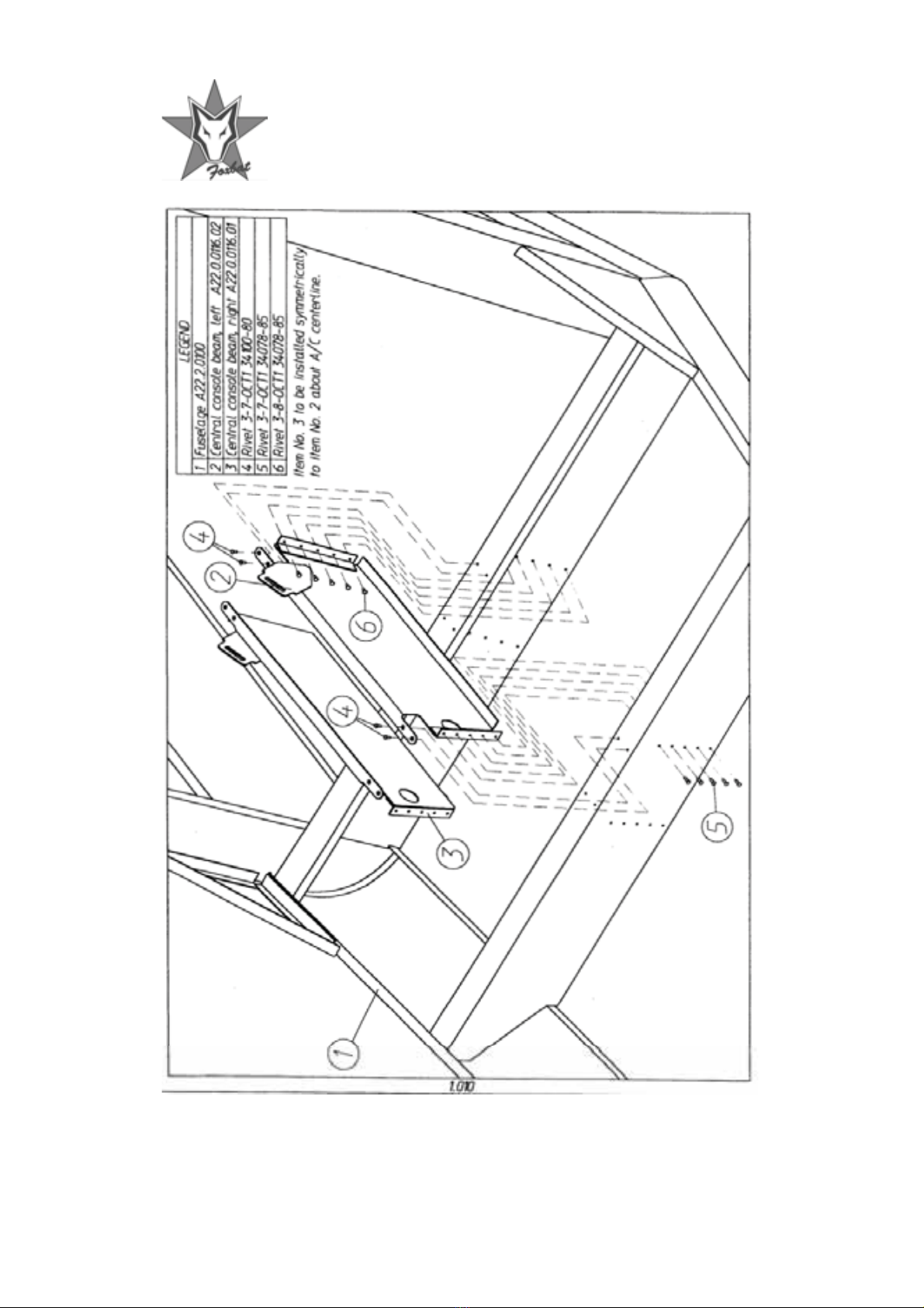
PAGE ONE
DRAWING NUMBER 1.010
Installing the Central Console Beams
SEE DRAWING FOR PARTS REQUIRED
Recommended job for two persons with fuselage monocoque supported as
required
1. Locate and inspect the left and right central console beams as
illustrated in the drawing.
2. Offer up both parts ensuring that their orientation is exactly as shown in
the drawing. Clico in place then check the fit and alignment.
3. Re-check steps 1 and 2.
4. Working from side to side alternately replace the clicos with rivets.
5. Thoroughly examine the finished work and compare it with the drawing.
Notes:
Pa
g
e 10 - © SilverWin
g
Aviation
,
2005

Pa
g
e 11 - © SilverWin
g
Aviation
,
2005
PAGE TWO
DRAWING NUMBER 1.020
Installing the Landing Gear Support Beams
SEE DRAWING FOR PARTS REQUIRED
Recommended job for two persons with the fuselage monocoque supported
as required.
1. Locate and inspect the left and right landing gear (LG) beams illustrated
in the drawing.
2. Offer up both parts to the fuselage ensuring that their orientation is
exactly as shown in the drawing. Clico in place.
3. Re-check steps 1 and 2.
4. Working from side to side alternately replace the clicos with rivets.
5. Thoroughly examine the finished work and compare it with the drawing.
Notes:

Pa
g
e 12 - © SilverWin
g
Aviation
,
2005

Pa
g
e 13 - © SilverWin
g
Aviation
,
2005
PAGE THREE
DRAWING NUMBER 1.030
Installing the Door Gussets
SEE DRAWING FOR PARTS REQUIRED
Recommended job for two persons with fuselage monocoque supported as
required
1. Locate and inspect the angle pieces and gussets as illustrated in the
drawing (left and right sets).
2. Offer up the three parts to the fuselage left side ensuring that their
orientation is exactly as shown in the drawing. Clico in place then check
the fit and alignment.
3. Re-check steps 1 and 2.
4. Working from end to end alternately replace the clicos with rivets.
5. Thoroughly examine the finished work.
6. Repeat on right-hand side.
Notes:

Pa
g
e 14 - © SilverWin
g
Aviation
,
2005

Pa
g
e 15 - © SilverWin
g
Aviation
,
2005
PAGE FOUR
DRAWING NUMBER 1.040
Installing the Door Hinges
SEE DRAWING FOR PARTS REQUIRED
Recommended job for one person with the fuselage monocoque supported
as required
1. Locate and inspect door hinges as illustrated in the drawing. Select the
correct size bolts with stiff nuts and washers.
2. Loosely assemble both hinges in turn on the left side exactly as shown on
the drawing.
3. Re-check steps 1 and 2.
4. Tighten stiff-nuts until the hinges are snug and firm. Don’t over-tighten.
5. Thoroughly examine the finished work.
6. Repeat on right-hand side.
Notes:

Pa
g
e 16 - © SilverWin
g
Aviation
,
2005

Pa
g
e 17 - © SilverWin
g
Aviation
,
2005
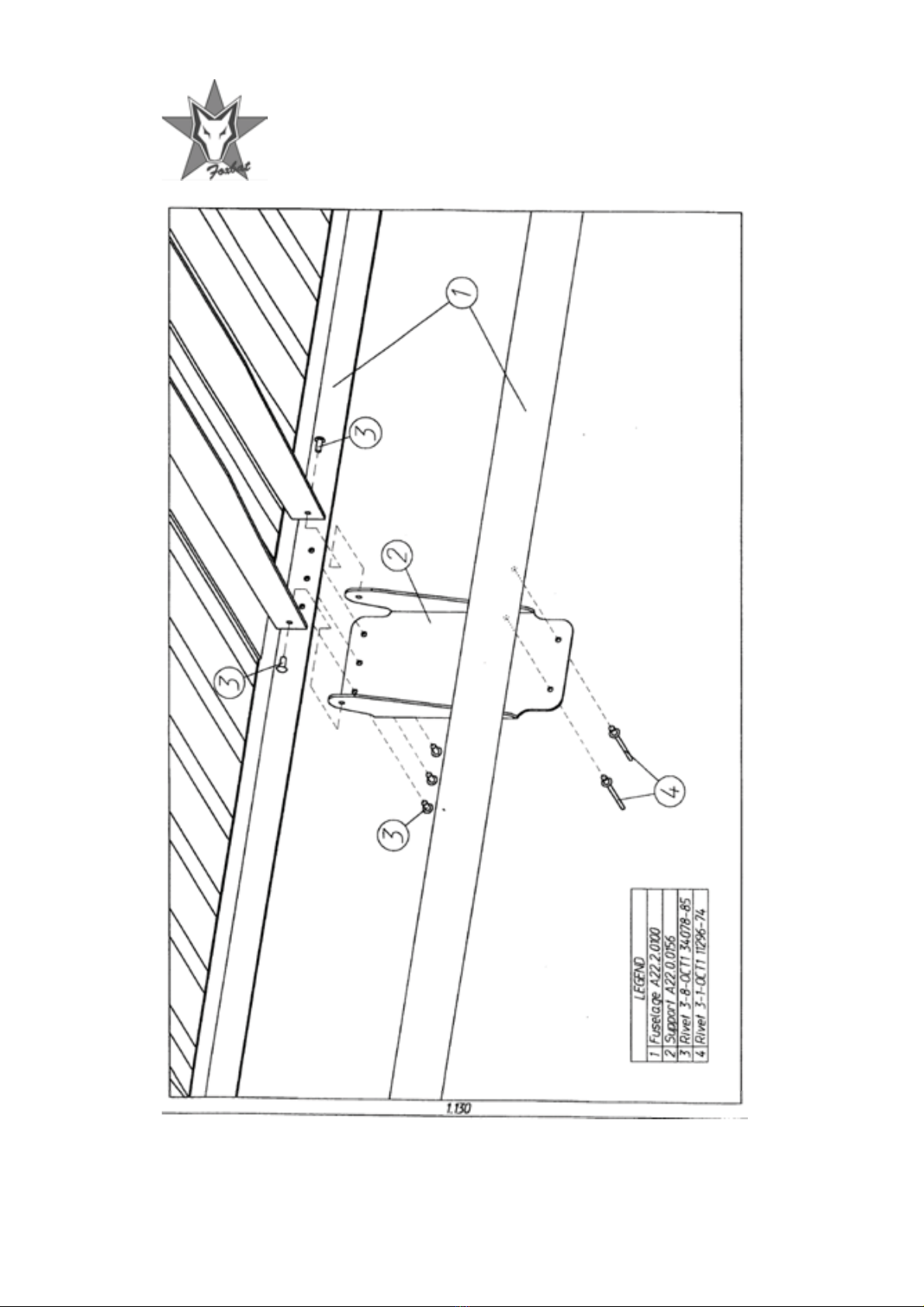
PAGE FIVE
DRAWING NUMBER 1.130
Installing the Upper Central Support
SEE DRAWING FOR PARTS REQUIRED
Recommended two persons job with the fuselage monocoque supported as
required
1. Locate and inspect the support bracket as illustrated in the drawing.
2. Offer up parts and pre-assemble with clicos exactly as shown in the
drawing.
3. Re-check steps 1 and 2. When you are completely satisfied that the
assembly is correct replace clicos with rivets working outwards from the
top centre.
4. Very carefully centre-punch, drill and pop-rivet the bottom of the
bracket to the cross-spar as shown in the drawing. Make certain to use
the correct drill and rivet size. Double-check before drilling.
5. Thoroughly examine the finished work.
Notes:
Pa
g
e 18 - © SilverWin
g
Aviation
,
2005

Pa
g
e 19 - © SilverWin
g
Aviation
,
2005
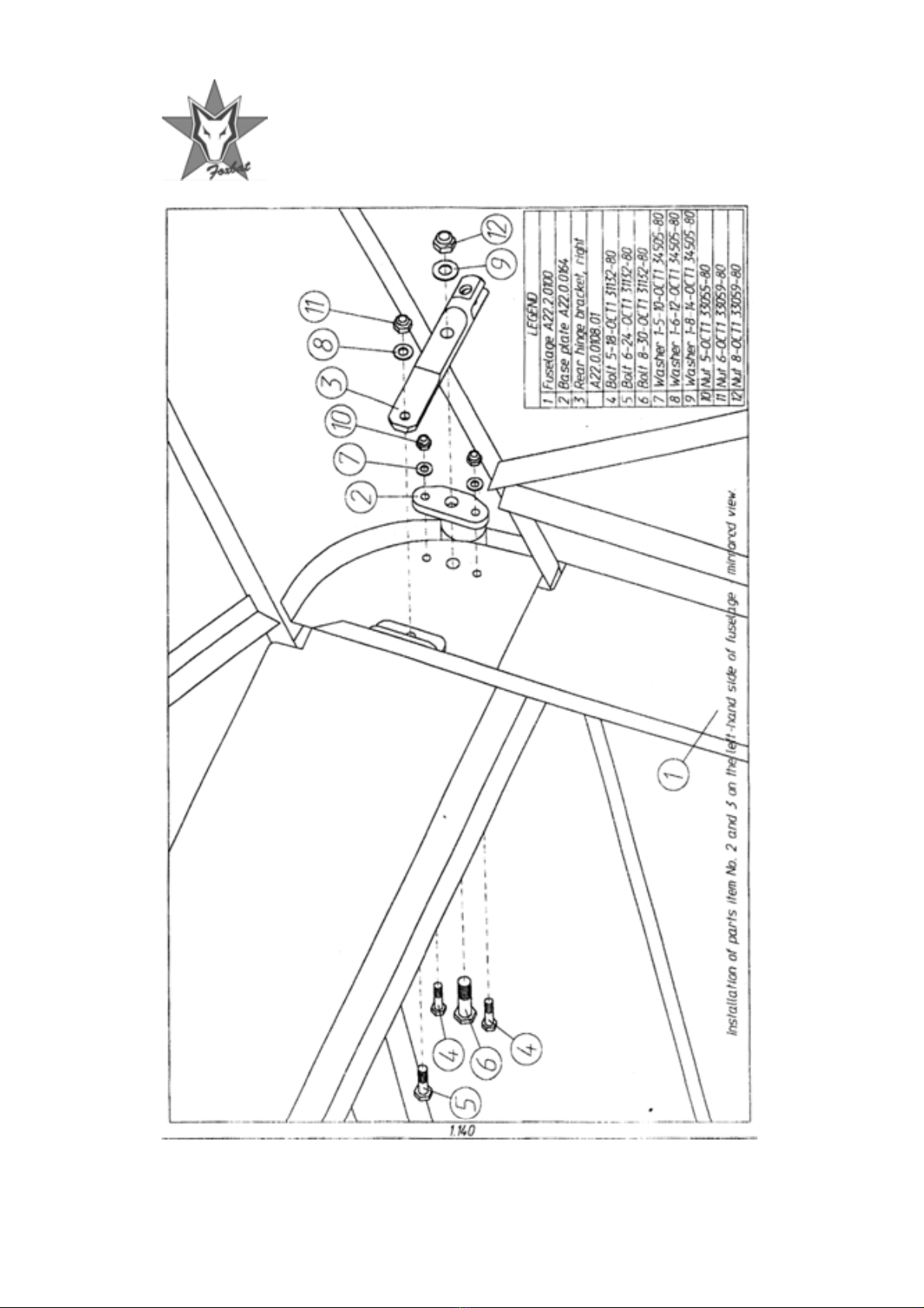
PAGE SIX
DRAWING NUMBER 1.140
Installing the Wing Rear Hinge Bracket
SEE DRAWING FOR PARTS REQUIRED
Recommended one person job with the fuselage monocoque supported as
required
1. Locate and inspect base plate and rear hinge bracket as illustrated in
the drawing. Select correct sized bolts with stiff-nuts and washers.
2. Offer up and loosely assemble parts exactly as shown in the drawing.
3. Re-check steps 1 and 2.
4. Tighten stiff-nuts until the assembly is snug and firm. Don’t over-
tighten.
5. Thoroughly examine finished work.
6. Repeat on left-hand side.
Notes:
Pa
g
e 20 - © SilverWin
g
Aviation
,
2005

Pa
g
e 21 - © SilverWin
g
Aviation
,
2005
PAGE SEVEN
DRAWING NUMBER 1.150
Installing the LG Spring Upper Brackets and Braces
SEE DRAWING FOR PARTS REQUIRED
Recommended one person job with fuselage supported as required
1. Locate and inspect LG spring bracket and brace as illustrated on the
drawing. Select the correct size bolts with stiff-nuts and washers.
2. Offer up and loosely assemble parts exactly as shown on the drawing.
3. Re-check steps 1 and 2.
4. Tighten stiff-nuts until the assembly is snug and firm. Don’t over-
tighten.
5. Thoroughly inspect finished work.
6. Repeat on right-hand side.
Notes:
Popular Toy manuals by other brands


REVELL
REVELL SUMMER ACTION FLYING LIGHTS Assembly manual

Vmar
Vmar CESSNA L-19 BIRD DOG Assembly & operation manual

Hasbro
Hasbro Decepticon Midnighter XR-4 81056 instructions

Flyzone
Flyzone B-25 mitchell user manual

LeapFrog
LeapFrog Sing & Snuggle Violet Parents' guide

VQ Models
VQ Models CESSNA 188 AGWAGON instruction manual