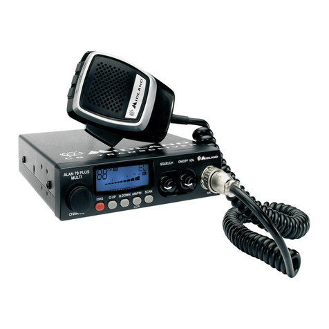
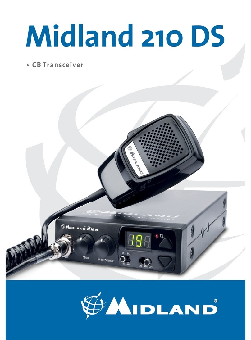
Midland 220 User manual

1
ITALIANO
INDICE
DESCRIZIONE COMANDI 2
INSTALLAZIONE 5
Collegamento elettrico 5
ISTRUZIONI DI FUNZIONAMENTO MIDLAND 220 5
SELEZIONE BANDE DI FREQUENZA 6
Tabella bande di frequenza 6
CARATTERISTICHE TECNICHE 7
Midland 220 è un nuovo CB mobile Multi Standard, essenziale nelle sue funzionalità ma nello
stesso tempo con caratteristiche tecniche all’avanguardia, come il ltro per la soppressione del
rumore ESP2.
Grazie al Midland 220 ora è possibile soddisfare le richieste di un apparato da installare in modo
semplice e “pulito” negli alloggiamenti DIN già presenti sui veicoli (tipicamente dedicati alle
autoradio).
Come richiesto da questa modalità di installazione l’altoparlante è posizionato sul frontale del CB
per garantire una resa acustica ottimale.
Nella confezione è fornito il microfono con pulsanti up/down e sia la staffa per il ssaggio orizzontale
sia l’adattatore per l’alloggiamento DIN.

2
ITALIANO
DESCRIZIONE COMANDI
1. Selettore canali: permette la selezione manuale dei canali
2. Display retroilluminato multifunzione:
A) Numero canali selezionati (da 1 a 40) o frequenza corrispondente.
B) Attivazione tastoFREQ
C) ESP: attivazione soppressore dinamico dei disturbi.
D) EMG: indicatore attivazione canali 9 / 19 o canale in uso.
E) M1-M4: indicatori memorie canali.
F) Indica la banda di frequenza selezionata.
G) Viene visualizzato quando la radio trasmette in bassa potenza (condizione che si verica
solo per determinate bande di frequenza – vedi tabella bande).
H) RX/TX: indicatore di ricezione (RX) e trasmissione (TX).
I) AM/FM: indicatore del modo di emissione.
J) Indicatore di intensità del segnale ricevuto e di potenza di segnale trasmesso.
3. Pulsante “Cambio colore”: premendo con un’estremità il pulsante all’interno del foro, si può
cambiare il colore della retroilluminazione e scegliere uno tra i seguenti colori: bianco, giallo,
viola, rosso, azzurro, verde, blu, no colore.
4. Pulsante “AM/FM (LCR)”: per selezionare il modo di emissione (AM/FM). Se si seleziona una
banda di frequenza che opera solamente in modalità FM, il tasto “AM/FM” attiva la funzione
LCR (richiamo ultimo canale selezionato).
5. Manopola “Squelch”: regolazione livello di soglia della ricezione. Per la massima sensibilità
del ricevitore è preferibile che il comando sia regolato solo al preciso livello dove il rumore di
fondo del ricevitore viene eliminato.
EXT-SP S-METER
ANT
+RED
-BLK
2 4 8 11 12
131105967
3
EXT-SP S-METER
ANT
+RED
-BLK
J A G
H
I
CEDB
F

3
ITALIANO
6. Manopola “ON/OFF-VOLUME”:
Posizione “OFF”: Apparato spento.
Posizione “Volume”: Ruotando la manopola, regolare il volume al livello desiderato.
7. Presa microfono: inserire lo spinotto del microfono nella presa. Con i tasti “UP/DOWN” del
microfono, si potranno cambiare manualmente i canali.
8. Pulsante “EMG”: Canale d’emergenza. Premendo questo tasto ci si posizionerà automatica-
mente sui canali 9/19 (canali di emergenza). Sul display lampeggerà EMG e non sarà possibile
cambiare accidentalmente il canale.
9. Manopola ‘’MIC-GAIN’’: Controllo dell’amplicazione microfonica in trasmissione. Utilizzare il
microfono ricercando sperimentalmente la posizione ottimale sia come distanza dalla bocca,
che di livello di amplicazione, in modo da ottenere la migliore modulazione possibile.
10.Manopola ‘’RF-GAIN’’: Controllo della sensibilità in ricezione: ruotando la manopola in senso
orario, si ottiene un aumento della sensibilità; ruotandola in senso antiorario, si ottiene una
diminuzione della sensibilità. Ciò è utile in presenza di forti segnali.
11.Tasto “N.K./ESP”
Tasto di attivazione del soppressore dinamico dei disturbi.
12.Tasto FREQ
Questo tasto permette, a scelta dell’utente, di:
visualizzare il canale o la frequenza operativa premendo “FUNC” per circa 3 secondi.
attivare le seconde funzioni dei tasti “M” (M1/M4).
M1/M4:
La radio ha la possibilità di memorizzare e di richiamare all’occorrenza 2 canali a piacimento
precedentemente memorizzati. Per memorizzarne uno, procedere come segue:
A) Selezionare il canale che si desidera memorizzare tramite il selettore canali o i tasti UP/
DOWN sul microfono;
B) Premere il tasto “FREQ”: il display mostrerà una “F”;
C) Tenere premuto per circa tre secondi il tasto “AM/FM/LCR”: la radio emetterà un “BIP” e il
display mostrerà la scritta “M4”.
Per memorizzare altri canali ripetere i punti A e B e premere il tasto “EMG”.
Per richiamare un canale precedentemente memorizzato premere il tasto “FREQ” e di seguito
il tasto “AM/FM/LCR” (M4) o “EMG” (M1).
13. Altoparlante frontale

4
ITALIANO
PANNELLO POSTERIORE
14.Connettore antenna: è previsto il connettore SO 239.
15.Presa EXT: presa altoparlante esterno (questo collegamento esclude l’uso dell’altoparlante in-
terno).
16.Presa S. Meter: permette il collegamento di uno strumento esterno.
17.Power 13.8 VCC: presa d’alimentazione.
MICROFONO
1. PTT: pulsante di trasmissione
2. Pulsanti UP/DOWN: selezione canali verso l’alto (UP)
e verso il basso (DOWN)
3. Connettore microfonico 6 pin
EXT-SP S-METER
ANT
+RED
-BLK
14 15 16
17
EXT-SP S-METER
ANT
+RED
-BLK
2
1
3

5
ITALIANO
INSTALLAZIONE
Ricercare e localizzare, sul mezzo mobile, la posizione per installare l’apparato, utilizzando la staffa
di supporto in dotazione o, eventualmente, un estraibile. Tale posizionamento deve essere fatto in
modo da non creare intralcio a chi guida, ma deve anche essere facilmente accessibile.
Praticare i fori (diametro di circa 3 mm) in una parte metallica per il ssaggio con le viti. Posizionare
l’apparato nella staffa di ssaggio. Controllare che le viti siano ben serrate, in considerazione delle
notevoli vibrazioni create dal mezzo mobile.
COLLEGAMENTO ELETTRICO
Prima di procedere in questa operazione, controllare che il ricetrasmettitore sia spento (posizione
OFF).
L’apparato è dotato di un cavetto d’alimentazione bicolore con un portafusibile inserito sul cavo
rosso (positivo). Nel collegamento, è molto importante rispettare la polarità anche se l’apparato è
protetto contro l’inversione accidentale.
Di norma si identica il polo positivo con il colore rosso o con il segno “+”, e il polo negativo con il
colore nero o con il segno “-”.
Gli stessi segni (o colori) identicativi li troveremo sulla batteria (accumulatore od altro) e nella
scatola dei fusibili dell’automobile. Si raccomanda di collegare in modo corretto e stabile i terminali
del cavetto alla batteria.
INSTALLAZIONE DELL’ANTENNA
Informazioni utili:
1. Installare l’antenna nella parte più alta del veicolo
2. Maggiore è la lunghezza dell’antenna e migliore sarà il suo rendimento
3. Se possibile, installare l’antenna al centro della supercie metallica scelta
4. Tenere il cavo dell’antenna lontano da fonti di disturbi elettrici
5. Assicurarsi di avere una buona massa
6. Evitare danni ai cavi
Attenzione: Non usare mai la radio CB senza aver installato un’antenna appropriata per non
correre il rischio di danneggiare il trasmettitore; per la stessa ragione controllare periodicamente il
ROS tramite l’apposito strumento.
ISTRUZIONI DI FUNZIONAMENTO MIDLAND 220
Dopo aver installato e cablato il vostro CB e la vostra antenna, seguire attentamente le seguenti
istruzioni per raggiungere un funzionamento soddisfacente del vostro apparato.
1. Avvitare la spina nella presa del microfono sul pannello e controllare il montaggio
2. Assicurarsi che l’antenna sia collegata al proprio connettore
3. Assicurarsi che il comando di squelch sia completamente ruotato verso sinistra
4. Accendere l’apparato e regolare il comando del volume per un buon livello sonoro
5. Selezionare il canale desiderato
6. Per trasmettere, premere il pulsante di trasmissione PTT sul microfono
7. Per ricevere, rilasciarlo
6
ITALIANO
SELEZIONE BANDE DI FREQUENZA
La scelta delle bande di frequenza deve essere eseguita a seconda del paese nel quale si
intende operare.
Procedimento:
1. Spegnere la radio.
2. Accendere l’apparecchio tenendo premuto il tasto “N.K./ESP”.
3. Selezionare la banda di frequenza desiderata tramite i tasti “UP” / “DOWN”.
Attendere 5 secondi circa oppure spegnere e riaccendere l’apparato.
NOTA1: nelle bande di frequenza UKE o UKC è possibile selezionare direttamente l’altra banda
premendo il tasto “AM/FM/LCR” per 3 secondi circa.
NOTA2: se si seleziona un banda di frequenza che opera solamente la modalità FM, il tasto “AM/
FM/LCR” attiva la funzione LCR (richiamo ultimo canale selezionato).
TABELLA BANDE DI FREQUENZA:
Sigla sul
display Paese Banda Frequenza
IItalia 40CH AM/FM 4W Fx 26,965-27,405 MHz
I2 Italia 34CH AM/FM 4W Fx 26,875-27,265 MHz
DGermania 80CH FM 4W 12CH AM 1W Fx 26,565-27,405 MHz
D2 Germania 40CH FM 4W 12CH AM 1W Fx 26,965-27,405 MHz
D3 Germania 80CH FM 4W 40CH AM 1W Fx 26,565-27,405 MHz
EU Europa 40CH FM 4W 40CH AM 1W Fx 26,965-27,405 MHz
EC Europa 40CH FM 4W Fx 26,965-27,405 MHz
ESpagna 40CH AM/FM 4W Fx 26,965-27,405 MHz
FFrancia 40CH FM 4W 40CH AM 1W Fx 26,965-27,405 MHz
UKE Inghilterra 40CH FM 4W Fx 26,60125-27,99125MHz
UKC Inghilterra 40 CH FM 4W CEPT Fx 26,965-27,405MHz
PL Polonia 40CH AM/FM 4W Fx 26,960 – 27,400MHz
ATTENZIONE!
Lo standard sicuramente riconosciuto in tutti i paesi europei è 40CH FM 4W (EC)– vedi tabella
“Restrizioni all’uso”.

7
ITALIANO
CARATTERISTICHE TECNICHE
GENERALI
Canali .....................................................................................................40 FM (vedi tabella bande)
Gamma di frequenza ........................................................................................ 25.615-30.105 MHz
Controllo di frequenza ............................................................................................................ a PLL
Temperatura ................................................................................................................... 10° ± 55°C
Tensione d’alimentazione .......................................................................................13.8V CC ±15%
Ciclo di utilizzo............................................................................................. 5/5/90 (1 ora di utilizzo)
Dimensione ..........................................................................................170 (L)* 52 (A)* 170 (P) mm
Peso ...................................................................................................................................1,020 kg
RICEVITORE
Sistema ricevente .................................................................Supereterodina a doppia conversione
Frequenza intermedia.................................................................I° IF: 10.695 MHz II° IF: 455 KHz
Sensibilità ..................................................................................................... 1 µV per 20dB SINAD
Potenza d’uscita audio @10% THD .........................................> 4.0W @ 8 Ohm (speaker esterno)
...................................................................................................> 2.0W @ 8 Ohm (speaker interno)
Distorsione audio .......................................................................................... meno del 3% @ 1KHz
Assorbimento all’attesa ..........................................................................................................200mA
TRASMETTITORE
Potenza d’uscita ................................................................................................... 4W @ 13.8V CC
Modulazione ...................................................................................................FM: 1,8KHz ± 0,2KHz
............................................................................................................................AM: da 85% a 95%
Corrente assorbita .............................................. 1100mA (posizione potenza senza modulazione)
Le speciche sono soggette a variazione senza preavviso.
Un dispositivo di sezionamento adatto deve essere previsto nell’impianto elettrico. Tale dispositivo
deve disconnettere entrambi i poli simultaneamente.


9
ENGLISH
INDEX
FUNCTIONS AND LOCATION OF THE CONTROLS 10
INSTALLATION 13
Power supply 13
Installing an antenna 13
HOW TO OPERATE YOUR TRANSCEIVER 13
Frequency band selection 13
Frequency band chart 14
TECHNICAL SPECIFICATIONS 15
Midland 220 is the brand new Multi Standard CB transceiver, essential in its functionalities but with
advanced performances, such as the ESP2 (noise killing device).
Midland 220 is a very practical radio, very easy to install even into the DIN housing of the vehicles
(usually suitable for car radios).
As required by this kind of installation the speaker is on the front panel to guarantee a high-quality
acoustic level.
MIDLAND 220 is supplied with a microphone with UP/DOWN buttons, mounting bracket and
adaptor for DIN mounting.

10
ENGLISH
FUNCTIONS AND LOCATION OF THE CONTROLS
1. Channel selector: it permits the manual channel selection.
2. Multifunction back-lighted display. It shows:
A) Selected channel (from 1 up 40) or operative frequency
B) FREQ button activated
C) ESP: reducing noise device activated
D) EMG: indicates channel being used or when the emergency channels are activated
E) M1 – M4: memory channel indicator
F) Indicates the frequency band selected
G) Appears when the radio transmits in low power (this condition happens only in some
frequency bands – see the chart at the end of the manual)
H) RX/TX: reception (RX) / transmission (TX) indicator.
I) AM/FM mode.
J) Received signal strength and transmitted signal power.
3. Button for changing colour: by pushing a pointed object into the hole, you can change the
backlight colour of the display. You can choose amongst the following colours: white, yellow,
violet, red, light blue, green, blue or no colour.
4. “AM/FM”(LCR) button: To select AM or FM mode. If you select a frequency band operating in
FM mode only, this button enables the LCR function (Last Channel Recall).
5. “Squelch” Control: For the maximum receiver sensitivity, the control must be regulated exactly
where the receiver background noise disappears.
EXT-SP S-METER
ANT
+RED
-BLK
2 4 8 11 12
131105967
3
EXT-SP S-METER
ANT
+RED
-BLK
J A G
H
I
CEDB
F

11
ENGLISH
6. “ON/OFF Volume” Control. In “OFF” position your transceiver is OFF. “VOLUME” position: by
turning this knob, you set the audio level.
7. Microphone jack: Insert the mic connector into this jack.
8. EMG button: Emergency channel. By pressing it, the unit will be automatically positioned on
CH 9/19 (emergency channels). The display will show “EMG”. It will not be possible to acciden-
tally change the channel.
9. “Mic (Microphone) Gain Control”: in TX mode, it controls the microphone amplication.
The best results are obtained by getting the best modulation: use the mike by trying to nd the
optimal amplication level and distance from your mouth.
10.“RF” (Radio Frequency) Gain Control: it controls the reception sensitivity. To increase the
sensitivity, simply turn it clockwise. Sensitivity decreases turning it counterclockwise. Low sen-
sitivity is useful in case of very strong signals.
11.“N.K./ESP” button
Pressing this switch, you activate the noise killing device. Receiver noise and interference can
now be largely eliminated by the ESP2 system.
12.FREQ button
With this button, you can:
visualize the operative frequency (if you keep pressing the button for 3 seconds approx.), or
the channel in use;
activate the second functions of the “M” (M1/M4) buttons.
M1 / M4:
MIDLAND 220 has the possibility to store and to recall, when necessary, 2 channels previously
memorized.
To memorize one channel, follow the procedure herebelow:
A) Select the channel with the appropriate selector or the “UP/DN” buttons on the microphone;
B) Push the “FREQ” button: the display will show “F”;
C) Keep pressed the “AM/FM/LCR” button for 3 seconds: you will hear a “BIP” and the display
will show “M1”.
To memorize the other channels, repeat these steps and press “EMG”.
To recall a channel previously stored, push the “FREQ” switch and then “AM/FM/LCR” (M4) or
“EMG” (M1).
13.Front speaker

12
ENGLISH
REAR PANEL
14.Antenna connector (SO239 connector type)
15.”EXT” jack: external loudspeaker jack.(the internal loudspeaker is excluded)
16.S.Meter jack: it allows an external “S. Meter” connection
17.Power 13.8V DC: power supply cable
MICROPHONE
1. PTT: transmission button
2. UP/DOWN buttons: manual channel selector.
3. 6 pin microphone connector
EXT-SP S-METER
ANT
+RED
-BLK
14 15 16
17
EXT-SP S-METER
ANT
+RED
-BLK
2
1
3

13
ENGLISH
INSTALLATION
Safety and convenience are the primary considerations for mounting any piece of mobile equipment.
All controls must be readily available to the operator without interfering with the movements
necessary for safe operation of the vehicle. Interference from the connecting cables may contribute
to the loss of control of the vehicle.
Set the proper position in the car to install the transceiver using the supplied supporting bracket or
eventually the DIN mounting bracket.
Tighten the retaining screws. The mounting bracket must be close to metallic parts.
POWER SUPPLY
Be sure the transceiver is OFF. In the direct-voltage power supply, it is very important to observe
the polarity even if the unit is protected against the accidental inversion:
Red = positive pole (+)
Black = negative pole (-)
The same colours are present on the battery and in the fuse box of the car. Correctly connect the
cable terminal to the battery.
INSTALLING AN ANTENNA
1. Place the antenna as high as possible
2. The longer the antenna is, the better will be the performance
3. If possible, mount the antenna in the centre of whatever surface you choose
4. Keep antenna cable away from noise sources, such as the ignition switch, gauges,etc.
5. Make sure you have a solid metal-to-metal ground connection.
6. Prevent cable damage during antenna installation.
WARNING: To avoid damage, never operate your CB radio without connecting a proper antenna.
A periodical control of the cable and of the S.W.R. is recommended.
HOW TO OPERATE YOUR TRANSCEIVER
1. Screw the microphone plug into the microphone jack.
2. Make sure your antenna is connected to the antenna connector.
3. Make sure the SQUELCH control is turned fully conterclockwise.
4. Turn on the unit and adjust the volume control.
5. Select your desired channel.
6. To transmit, press the PTT button and speak in a normal tone of voice.
7. To receive, release the PTT button.
FREQUENCY BAND SELECTION
The frequency bands must be chosen according to the country where you are going to operate.
Procedure:
1. Switch off the unit.
2. Turn it on while pushing the “N.K./ESP” button.
3. Select the desired frequency band by pushing the UP / DOWN buttons (see the chart here
below).
Wait for 5 seconds or switch off and then on the radio.
NOTE1: In the UKE or UKC frequency bands, you can select directly the other band by pushing the

14
ENGLISH
“AM/FM/LCR” button for 3 seconds.
NOTE2: If you select a frequency band which operates in FM mode only, the “AM/FM/LCR” control
enables the LCR function (last channel recall).
FREQUENCY BAND CHART
Digits
displayed Country Band Frequency
IItaly 40CH AM/FM 4W Fx 26,965-27,405 MHz
I2 Italy 34CH AM/FM 4W Fx 26,875-27,265 MHz
DGermany 80CH FM 4W 12CH AM 1W Fx 26,565-27,405 MHz
D2 Germany 40CH FM 4W 12CH AM 1W Fx 26,965-27,405 MHz
D3 Germany 80CH FM 4W 40CH AM 1W Fx 26,565-27,405 MHz
EU Europe 40CH FM 4W 40CH AM 1W Fx 26,965-27,405 MHz
EC Europe 40CH FM 4W Fx 26,965-27,405 MHz
ESpain 40CH AM/FM 4W Fx 26,965-27,405 MHz
FFrance 40CH FM 4W 40CH AM 1W Fx 26,965-27,405 MHz
UKE England 40CH FM 4W Fx 26,60125-27,99125MHz
UKC England 40 CH FM 4W CEPT Fx 26,965-27,405MHz
PL Poland 40CH AM/FM 4W Fx 26,960 – 27,400MHz
ATTENTION!
The frequency band allowed all over Europe is 40 CH FM 4W (EC).

15
ENGLISH
TECHNICAL SPECIFICATIONS
GENERAL
Channels ..............................................................................40 FM (see the frequency band chart)
Frequency Range ......................................................................................... 25.615 to 30.105 MHz
Frequency Control ..................................................................................................................... PLL
Operating Temperature Range ....................................................................................... 10°/+55° C
DC input voltage .....................................................................................................13.8V DC ±15%
Duty cycle....................................................................................................... 5/5/90 (1 hour of use)
Size .....................................................................................................170 (L)x 52 (H)x 170 (D) mm
Weight .................................................................................................................................1,020 kg
RECEIVER
Receiving system ........................................................................dual conversion superheterodyne
Intermediate frequency ..............................................................I° IF: 10.695 MHz II° IF: 455 KHz
Sensitivity ....................................................................................................... 1µV for 20 dB SINAD
Audio output power @10% THD ............................................> 4.0W @ 8 Ohm (external speaker)
..................................................................................................> 2.0W @ 8 Ohm (internal speaker)
Audio distortion .............................................................................................less than 3% @ 1 KHz
Current drain at stand/by .......................................................................................................200mA
TRANSMITTER
Output power......................................................................................................... 4W @ 13.8V DC
Modulation......................................................................................................AM: from 85% to 95%
......................................................................................................................FM: 1,8 KHz ± 0,2 KHz
Current drain...............................................................1100mA (Power position with no modulation)
All specications are subject to change without notice.
A readily accessible disconnect device shall be incorporated in the installation wiring.
The disconnect device shall disconnect both poles simultaneously.


17
DEUTSCH
INHALT
BEDIENELEMENTE 18
INSTALLATION 21
Stromversorgung 21
Antenne anschließen 21
GERÄT IN BETRIEB NEHMEN 21
Ländereinstellung 21
Ländercodes und Frequenzbandtabelle 22
TECHNISCHE DATEN 23
Midland 220 ist unser brandneuer Multi Standard CB Transceiver mit allen wesentlichen Funktionen
und sinnvoller Zusatzausstattung, wie dem ESP2 Rauschunterdrückungssystem.
Midland 220 ist praktisch, sehr leicht zu installieren und passt auch in DIN Schächte für die
Autoradioinstallation.
Wie für diese Art des Einbaus empfohlen, verfügt das Gerät über einen Frontlautsprecher mit
hervorragenden Wiedergabeeigenschaften.
MIDLAND 220 wird mit UP/DOWN Mikrofon, Montagebügel und DIN-Schacht Einbauadapter
geliefert.

18
DEUTSCH
BEDIENELEMENTE
1. Kanalwähler: zum Einstellen des gewünschten Kanals.
2. Multifunktions-Display mit Hintergrundbeleuchtung:
A) Eingestellter Kanal (von 1 bis 40 (80)) oder Frequenzanzeige
B) FREQ Anzeige aktiviert
C) ESP: Rauschunterdrückung aktiviert
D) EMG: zeigt an wenn Notrufkanal 9 / 19 aktiviert
E) M1 – M4: Memory-Kanal-Anzeige
F) Zeigt die gewählte Ländereinstellung an
G) Erscheint wenn das Gerät mit reduzierter Leistung (in einigen Ländern) arbeitet, siehe Liste
am Schluss der Anleitung
H) RX/TX: Anzeigen für Empfang (RX) / Senden (TX).
I) AM/FM Mode.
J) Signalstärke bei Empfang und relative Sendeleistung bei Senden.
3. Farbumschaltung: mit einem spitzen Gegenstand kann die Hintergrundfarbe der Displaybe-
leuchtung umgeschaltet werden. Möglich ist: weiß, gelb, violett, rot, hellblau, grün, blau oder
farblos.
4. “AM/FM”(LCR) Taste: Zur Auswahl zwischen AM oder FM . Bei einer Nur-FM Einstellung dient
der Taster zum Aufrufen des zuletzt gewählten Kanals (LCR=Last Channel Recall).
5. “Squelch” Einstellung = Rauschsperrenregler : Für höchste Empndlichkeit Regler in die
Stellung bringen, bei der das Grundrauschen gerade verschwindet.
EXT-SP S-METER
ANT
+RED
-BLK
2 4 8 11 12
131105967
3
EXT-SP S-METER
ANT
+RED
-BLK
J A G
H
I
CEDB
F

19
DEUTSCH
6. “ON/OFF Volume” Ein-Aus-Lautstärke. In “OFF” Stellung ist Gerät ausgeschaltet. “VOLUME”
Knopf drehen für gewünschte Lautstärkeeinstellung.
7. Mikrofonbuchse: Hier mitgeliefertes Mikrofon einstecken.
8. EMG Taste: Direktwahltaste für das Umschalten auf den Notruf- und Anrufkanal 9 bzw. 19.
Antippen der Taste schaltet vom Arbeitskanal nacheinander auf 9 bzw. 19 und zurück. Anzeige
EMG, sobald aktiviert.
9. “Mic Gain Control”= Mikrofonverstärkung: für den Sendebetrieb kann damit die
Ansprechempndlichkeit des Mikrofons geändert werden. Wir empfehlen, die optimale Stellung
entsprechend Ihren Sprechgewohnheiten auszuprobieren.
10.“RF” (Radio Frequency) Gain = HF Verstärkung: zur Einstellung der Empfänger-
. Höchste Empndlichkeit: im Uhrzeigersinn aufgedreht, niedrige Empndli-
chkeit (z.B. bei starken Signalen im Nahbereich) gegen den Uhrzeigersinn einstellen.
11.“N.K./ESP” Taste: Noise-Killer/ Geräuschunterdrückung
Drücken dieser Taste aktiviert die ESP 2 Schaltung, die Nebengeräusche und Störungen bei
Empfang weitgehend eliminieren kann.
12.FREQ Taste
With this button, you can:
schaltet zwischen der Standard Kanalnummern- oder der Frequenzanzeige um (3 Sekunden
drücken);
aktiviert die Zweitfunktion der “M” (M1/M4) Tasten.
M1 / M4:
MIDLAND 220 kann häug benutzte Kanäle bei Bedarf als Memorykanäle abspeichern.
Zum Abspeichern:
A) Kanal mit Kanalwähler oder “UP/DN” am Mikrofon auswählen.
B) “FREQ” Taste drücken- das Display zeigt “F”;
C) “AM/FM/LCR” Taste jetzt 3 Sekunden lang drücken: Sie hören einen Ton “BIP” and das
Display zeigt “M1”.
Für einen anderen Kanal verfahren Sie genauso und drücken anschließend “EMG”.
Zum Aufrufen gespeicherter Kanäle drücken Sie “FREQ” und dann “AM/FM/LCR” für (M4) oder
“EMG” für (M1).
13.Frontlautsprecher

20
DEUTSCH
GERÄTE-RÜCKSEITE
14.Antennenbuchse (SO239)
15.”EXT” : Buchse für externen Lautsprecher (der interne Lautsprecher schaltet dabei ab).
16.S.Meter Buchse: zum Anschluß eines externen Zusatz-S-Meters
17.Power 13.8V DC: Anschluß für Stromkabel an 12 V Bordnetze (10.8 bis 15.6 Volt DC)
MIKROFON
1. PTT: Sendetaste
2. UP/DOWN Tasten: manuelle Kanalwahl.
3. 6 pin Mikrofonstecker
EXT-SP S-METER
ANT
+RED
-BLK
14 15 16
17
EXT-SP S-METER
ANT
+RED
-BLK
2
1
3
Other manuals for 220
1
Table of contents
Languages:
Other Midland Radio manuals

Midland
Midland Radio ER300 Manual

Midland
Midland ML801 User manual

Midland
Midland WR120B Manual

Midland
Midland G7XT Manual

Midland
Midland SD-225V2 User manual

Midland
Midland 77-120ESP User manual

Midland
Midland G9 User manual

Midland
Midland 220 User manual

Midland
Midland DBR2500 User manual

Midland
Midland 1001z User manual

Midland
Midland GXT444 User manual

Midland
Midland PRO901 User manual

Midland
Midland 70-1526A User manual

Midland
Midland Alan 8001 XT User manual

Midland
Midland 70-530 User manual

Midland
Midland SYN-TECH III P25 - REV 6.0 User manual

Midland
Midland ML802 User manual

Midland
Midland M-Mini Manual

Midland
Midland M-88 Manual

Midland
Midland WR-100 User manual